Page is loading ...

Raytherm
®
Heating
Boilers
INSTALLATION AND
OPERATION MANUAL
AA
WARNING: Improper installation, adjustment, alteration, service or maintenance can cause property
damage, personal injury, exposure to hazardous materials* or loss of life. Review the information in this manual
to humans.
FOR YOUR SAFETY: Do not store or use gasoline or other flammable vapors and liquids or other com-
bustible materials in the vicinity of this or any other appliance. To do so may result in an explosion or
fire.
WHAT TO DO IF YOU SMELL GAS:
• Do not try to light any appliance.
• Do not touch any electrical switch; do not use any phone in your building.
• Immediately call your gas supplier from a neighbor’s phone. Follow the gas supplier’s instructions.
• If you cannot reach your gas supplier, call the fire department.
Installation and service must be performed by a qualified installer, service agency or the gas supplier.
This manual should be maintained in legible condition and kept adjacent to the boiler or in a safe place for future
reference.
P/N 240035 Rev. 40
CATALOG NO. 2000.50AM
Effective: 06-30-18
Replaces: 04-01-18
Models 0181-4001 Type H

2
Revision 40 reects the following changes:
Manual updated to the format style. Removed California Proposition 65 warning on page 3.
CONTENTS
1. WARNINGS ................................................................... 3
1.1. Pay Attention to These Terms ..............................3
2. BEFORE INSTALLATION ............................................ 4
2.1. Product Receipt ........................................................4
2.2. RatingandCertication .........................................4
2.3. ModelIdentication ................................................ 5
3. BOILER TYPES .............................................................. 5
3.1. Type H - Mechanical Modulating .......................5
3.2. Type H2 - Motorized Modulating ........................5
3.3. Type H3 - 2-Stage Controls ................................... 5
3.4. TypeH4-On-OControls .....................................5
3.5. Type H5 - Mechanical Modulating .....................5
3.6. Type H9 - 4-Stage.....................................................5
4. INSTALLATION ............................................................. 5
4.1. Installation Codes .................................................... 5
4.2. Clearances .................................................................6
4.3. Outdoor Boilers ........................................................6
4.4. High-Wind Conditions ............................................8
4.5. Combustion and Ventilation Air ..........................8
4.6. Outdoor Installations ..............................................8
4.7. Indoor Installations .................................................9
4.8. Vent Piping .............................................................. 11
4.9. Vent Damper Installation .................................... 12
4.10. Gas Supply Connections .................................... 14
4.11. Gas Pressure Regulator ...................................... 14
4.12. Venting of Diaphragm Gas Components ...... 14
5. CONTROLS..................................................................17
5.1. Economaster Controls ........................................ 17
5.2. Electronic Ignition ................................................ 17
5.3. Outdoor Air Reset Temperature Controller .. 19
5.4. Hydronic with Outdoor Air Reset ..................... 19
5.5. Hydronic,OutdoorAirResetwith
Indirect DHW .......................................................... 20
5.6. Direct Domestic Hot Water................................ 21
5.7. Operating Controls ............................................... 22
5.8. Limit Controls ......................................................... 23
.....................................................................25
6.1. Electrical Connections ........................................ 25
6.2. Pre Start-Up ............................................................ 25
6.3. General ..................................................................... 25
6.4. Filling System ......................................................... 25
6.5. Ethylene Glycol Systems .................................... 25
6.6. Initial Start-Up ........................................................ 25
6.7. For Models with Automatic Gas Valves ......... 25
6.8. After Start-Up ......................................................... 26
6.9. Inspections ............................................................. 26
6.10. Suggested Inspection Schedule ..................... 26
7. LOW NOX BOILERS ...................................................27
7.1. Models 0181 to 0401 ........................................... 27
7.2. Operation ................................................................. 27
7.3. Start-Up IID ............................................................. 27
7.4. Blower Adjustment ............................................... 27
7.5. Visual Inspection .................................................. 27
7.6. Electrical .................................................................. 27
7.7. Service ...................................................................... 29
7.8. Gas Valve Adjustment ......................................... 29
8. WIRING DIAGRAM ....................................................31
8.1. TypicalOn-OIntermittentIgnition
Control Wiring ....................................................... 31
9. TROUBLESHOOTING ................................................ 32
9.1. Electrical - Electronic Ignition IID .................... 32
10. MAINTENANCE ........................................................34
10.1. Service ...................................................................... 34
11. REPLACEMENT PARTS ...........................................36
12. WARRANTY ................................................................ 37

3
AA
DANGER: Make sure the gas on which the heater will
rating plate.
AA
WARNING: Should overheating occur or the gas
supply at a location external to the heater.
AA
WARNING: Do not use this heater if any part has
technician to inspect the heater and to replace any part
of the control system and any gas control which has been
under water.
AA
WARNING: Risk of electrical shock. More than one
disconnect switch may be required to de-energize the
equipment before servicing.
AA
CAUTION: This heater requires forced water
circulation when the burner is operating. See minimum
AA
CAUTION: Operation of this heater in
low-temperature systems requires special piping.
Harmful internal condensation will occur if the inlet water
temperature does not exceed 105°F (41°C). Warranty
claims will be denied when condensation occurs.
AA
CAUTION: If this heater is to be installed above
radiation level, it must be provided with a low water cut-
AA
CAUTION: If this heater is to be installed in a negative
or positive pressure equipment room, there are special
installation requirements. Consult factory for details.
1. WARNINGS
1.1. Pay Attention to These Terms
AA
WARNING: This unit contains refractory ceramic
as manufactured, does not contain respirable crystalline
silica. However, following sustained exposure to very
high temperatures [>2192°F (1200°C)], the RCF can
transform into crystalline silica (cristabolite). The
International Agency for Research on Cancer (IARC) has
as carcinogenic to humans.
When removing the burners or heat exchangers, take
precautions to avoid creating airborne dust and avoid
engineering controls such as local exhaust ventilation or
dust collecting systems to minimize airborne dust. Wear
appropriate personal protective equipment including
gloves, safety glasses with side shields, and appropriate
AA
DANGER
Indicates the presence of immediate hazards which will cause severe personal injury, death or
substantial property damage if ignored.
AA
WARNING
Indicates the presence of hazards or unsafe practices which could cause severe personal injury,
death or substantial property damage if ignored.
AA
CAUTION
Indicates the presence of hazards or unsafe practices which could cause minor personal injury
or product or property damage if ignored.
CAUTION
CAUTION used without the warning alert symbol indicates a potentially hazardous condition
which could cause minor personal injury or product or property damage if ignored.
NOTE
Indicates special instructions on installation, operation, or maintenance which are important but
not related to personal injury hazards.
AA
WARNING: To minimize the possibility of improper
heater:
• Always keep the area around the heater free of
liquids and vapors.
• Heater should never be covered or have any blockage
AA
WARNING: All venting types must be of the same
material or product throughout the entire exhaust
installation to ensure proper securing and sealing.
AA
WARNING: Propane appliances should not be
installed below-grade (for example, in a basement) if such
installation is prohibited by federal, state and/or local
laws, rules, regulations or customs.

4
AA
DANGER: Failure to install the draft hood and properly
vent the water heater to the outdoors as outlined in
the Venting section of this manual can result in unsafe
explosion, or asphyxiation from carbon monoxide, never
operate this water heater unless it is properly vented and
has an adequate air supply for proper operation. Be sure
to inspect the vent system for proper installation at initial
start-up; and at least annually thereafter. Refer to the
Maintenance section of this manual for more information
regarding vent system inspections.
AA
DANGER: When servicing or replacing components
that are in direct contact with the water, be certain that:
• There is no pressure in the heater. (Pull the release on
the relief valve. Do not depend on the pressure gauge
reading).
• The heater water is not hot.
•
AA
WARNING: Both propane and natural gas have an
odorant added to help detection. Some people may not
physically be able to smell or recognize this odorant. If
unsure or unfamiliar about the smell associated with
propane or natural gas, ask the gas supplier. Other
conditions, such as “Odorant Fade”, which causes the
odorant to “fade”, or diminish in intensity, can also hide or
AA
WARNING: UL-recognized fuel gas detectors are
recommended in all enclosed propane and natural gas
applications wherein there is a potential for an explosive
mixture of fuel gas to accumulate and their installation
should be in accordance with the detector manufacturer’s
recommendations and/or local laws, rules, regulations,
or customs.
NOTE: Raypak recommends laying out and installing the
vent system before installing water piping. This will ensure
that the venting system and associated components will
Thank you for purchasing a Raypak product. We hope you
willbesatisedwiththehighqualityanddurabilityofour
equipment.
2.1. Product Receipt
Onreceipt of the equipment,visually check for external
damage to the carton or the shipping crate. If either is
damaged, make a note on the Bill of Lading and report
the damage to the Carrier immediately. Remove the boiler
from the carton or the shipping crate.
On occasion, items are shipped loose. Be sure that you
receive the number of packages indicated on the Bill of
Lading.
When ordering parts, you must specify the Model and
Serial Number of the boiler. When ordering under warranty
conditions, you must also specify the date of installation.
Raypak recommends that this manual be reviewed
thoroughly before installing your Raypak boiler. If there
are any questions which this manual does not answer,
please contact your local Raypak representative.
Claims for shortages and damages must be led with
carrier by consignee. Permission to return goods must be
factory authorized and are subject to a stocking charge.
Purchased parts are subject to replacement only under
the manufacturer’s warranty. Debits for defective
replacement parts will not be accepted and will be
replaced in kind only per our standard warranties.
2.2.
The Raypak hydronic boilers are design-certied and
tested under the latest requirements of the American
National Standard, ANSI Z21.13. Each boiler has been
constructed and pressure tested in accordance with the
requirementsofSectionIVPartHoftheAmericanSociety
ofMechanicalEngineersCode,andfactoryre-tested.
All models are ASME-Rated and National Board
registered. Temperature and pressure gauge is standard.
Models0181-1826have2-passheatexchangers,5tubes
rstpass,4tubessecondpass.Models2100-4001have
2-passheatexchangers,9tubesperpass.Models0926-
4001 with cast-iron headers allow optional single-pass
heatexchangers.
All units are CSA-certied for low-lead content (<.25%).
Minimumwatertempof105°F(41°C)attheinlet.
AA
WARNING: Altering any Raypak pressure vessel by
installing replacement heat exchangers, tube bundle
headers, or any ASME parts not manufactured and/or
approved by Raypak will instantly void the ASME and/
or CSA ratings of the vessel and any Raypak warranty on
the vessel. Altering the ASME and/or CSA ratings of the
vessel also violates national, state, and local approval
codes.
2. BEFORE INSTALLATION
Raypak strongly recommends that this manual be re-
viewed thoroughly before installing your Raytherm boiler.
Please review the General Safety information before
installing the boiler. Factory warranty does not apply to
boilers that have been improperly installed or operated.
Refer to the warranty at the back of this manual.
Installationandservicemustbeperformedbyaqualied
installer, service agency, or gas supplier. If, after reviewing
this manual, you still have questions which this manual
does not answer, please contact your local Raypak
representative or visit our website at www.raypak.com.

5
2.3.
The model number of a boiler can be found on the Sales
Order and the boiler’s rating plate. The example below
identies what the characters of the model number
represent.
MODEL NUMBER EXAMPLE:
H
3 - 0 5 1 4 A
Series
Model Size
Representative of approximate MBTUH input
(Model 0514 has input of 511,500 BTUH)
Firing Mode
1Mechanical Modulation
2Motorized Modulation
3 2-Stage Firing
4 On-Off Firing
5 Low Temperature Mechanical Modulatio
n
9 4-Stage Firing
Application
H = Heating Boiler
Boiler rating plate showing model number
Figure 1.
3. BOILER TYPES
3.1. Type H - Mechanical Modulating
3.1.1. Models 0330-1826
Central heating boiler with 150°F (66°C) - 210°F (99°C)
mechanical modulating gas valve(s). The number of
valves varies with the model size.
3.2. Type H2 - Motorized Modulating
3.2.1. Models 0514-4001
Central heating boiler with a motorized modulating gas
valve. Modulating controller optional.
3.3. Type H3 - 2-Stage Controls
3.3.1. Models 0181-4001
Central heating boiler with single 2-stage gas valve and
optional 2-stage controller. Outdoor Air Reset controller
standard on models 0181-0261.
3.4.
3.4.1. Models 0181-4001
Centralheatingboilerwithon-oring.OutdoorAirReset
controller standard on models 0181-0261.
3.5. Type H5 - Mechanical
Modulating
3.5.1. Models 0330-1826
Central heating boiler with 110°F (43°C) - 170°F (77°C)
mechanicalmodulatinggasvalve(s).Thenumberofvalves
varies with the model size.
3.6. Type H9 - 4-Stage
3.6.1. Models 0514-4001
Central heating boiler with 4-stage ring. Controller
optional.
4. INSTALLATION
4.1. Installation Codes
The installation must conform with these instructions and
the latest editions of the National Fuel Gas Code ANSI
Z223.1, the National Electric Code ANSI/NFPA 70 and
local codes. In Canada installations must conform with the
current CAN/CSA B149 and the Canadian Electrical Code
CSA C22.1 C.E.C. Part 1 (C22.1). All boiler installations
must conform to ASME boiler code. Hot water pipes must
be installed with minimum clearances to combustible
materialasrequiredbycode.
4.1.1. Installation Base
The boiler should be mounted on a level, non-combustible
surface. Boiler must not be installed on carpeting. The
boiler can be installed on a combustible surface only when
asuitableoorshieldbaseisprovided.Raypakoersan
optionaloorshield base which can be factoryinstalled
on all indoor models. Do NOT use the shipping crate base
as an installation base.
NOTE:
ordering information for other models.
NOTE: The boiler should be located in an area where
water leakage will not result in damage to the area
adjacent to the appliance or to the structure. When such
locations cannot be avoided, it is recommended that a
suitable drain pan, adequately drained, be installed under
In addition, the boiler shall be installed such that the gas
ignition system components are protected from water
(dripping,spraying,rain,etc.)duringappliance operation
andservice(circulatorreplacement,controlreplacement,
etc.).

6
Boiler
Model No.
Base Part No.
Boiler
Model No.
Base Part No.
0182/0181
0260/0261
0330/0331
0400/0401
058313
058314
058315
058316
0926*
1083*
1178*
1287*
1414*
1571*
1758*
054597
054598
054599
054600
054601
058378
058379
0514
0624
0724
0824
056199
056200
056201
056202
0962
1125
1223
1336
1468
1631
1826
059233
059234
059235
059236
059237
059238
059239
* Modelswithfactory-installedoorshieldasstandard.BOLD type
indicatesLowNOxmodels.
Table A. Combustible Floor Shield Ordering Information
4.2. Clearances
4.2.1. Indoor Installations
Boiler
Location
Boiler Model No.
0181 to
0401
0514 to
0824
0926 to
1826
2100 to
4001
in. (mm)
Back 12(305) 12(305) 24(610) 24(610)
Right 12(305) 6(152) 24(610) 24(610)
Left 12(305) 18(457) 24(610) 24(610)
Vent* 6(152) 6(152) 6(152) 6(152)
Indoor Top 39(991) 36(914) 24(610) 24(610)
Outdoor Top Unobstructed NA
Floor
Combustible oor shield is required when
boiler is installed on a combustible surface.
For ordering information see Table A
Front
Provideatleast24"(610mm)forModels0181-
1826and48"(130mm)forModels2100-4001
in front of unit for removal and servicing of the
Controls and Burner Tray. Provide at least 18"
(457)onsideoppositewaterconnectionsfor
delimingofHeatExchangerTubes.
* Ventincludes factory-supplieddrafthoodand does notinclude eld-
supplied vent systems above the drafthood. On Models 2100-4001
drafthood is built into boiler.
Table B. Minimum Clearances from Combustible
Installations
12" MIN
(305 mm)
12" MIN
(305 mm)
4" MIN
(102 mm)
SHEET METAL
24 GAUGE
Figure 2. Alternate Method for Providing a Non-
Combustible Base
NOTE: The boiler shall be installed in a space large
in comparison to the size of the boiler. Large space is
total volume of the boiler.
Forced Air Inlet
4' (1.2 m)
Minimum
3' (0.9 m)
Minimum
10' (3 m)
Minimum
1' (0.3 m)
Minimum
4' (1.2 m)
Minimum
4' (1.2 m)
Minimum
Figure 3. Minimum Distances to Building Openings from
Where Flue Products Exit the Boiler
4.3. Outdoor Boilers
Theseboilersaredesign-certiedforoutdoorinstallation.
Boilers must not be installed under an overhang within 3'
(0.9m)fromthetopontheboiler.Three(3)sidesmustbe
open in the area under the overhang. Roof water drainage
must be diverted away from the boilers with the use of
gutters.
Thepointfromwheretheueproductsexittheboilermust
bea minimumof4'(1.2 m)below,4'(1.2 m)horizontally
fromor12"(305mm)aboveanydoor,windoworgravity
inlet to a building. The top surface of the boiler shall be at
least3'(0.9m)aboveanyforcedairinlet,orintakeducts
locatedwithinten10'(3m)horizontally.

7
Description Location
Boil Size
181 to 401 514 to 824 926 to 1826 2100 to 4001
a. 3-1/2"(89mm)thickmasonrywalls
without ventilated air space
Back 9(229) 9(229) 16(406) 16(406)
Right 9(229) 5(127) 16(406) 16(406)
Left 9(229) 12(305) 16(406) 16(406)
Vent 5(127) 5(127) 5(127) 5(127)
Indoor Top 39(991) 36(914) 24(610) 24(610)
Outdoor Top Unobstructed NA
b. 1/2"(13mm)insulationboardover1"(25
mm)glassberormineralwoolbatts
Back 6(152) 6(152) 12(305) 12(305)
Right 6(152) 3(76) 12(305) 12(305)
Left 6(152) 9(229) 12(305) 12(305)
Vent 3(76) 3(76) 3(76) 3(76)
Indoor Top 30(762) 24(610) 16(406) 16(406)
Outdoor Top Unobstructed NA
c. 0.024sheetmetalover1"(25mm)glass
berormineralwoolbattsreinforced
with wire on rear face with ventilated air
space
Back 4(102) 4(102) 8(203) 8(203)
Right 4(102) 3(76) 8(203) 8(203)
Left 4(102) 6(152) 8(203) 8(203)
Vent 3(76) 3(76) 3(76) 3(76)
Indoor Top 24(610) 18(457) 12(305) 12(305)
Outdoor Top Unobstructed NA
d. 3-1/2"(89mm)thickmasonrywallwith
ventilated air space
Back 6(152) 6(152) 8(203) 8(203)
Right 6(152) 6(152) 8(203) 8(203)
Left 6(152) 6(152) 8(203) 8(203)
Vent 6(152) 6(152) 6(152) 6(152)
Indoor Top 39(991) 36(914) 24(610) 24(610)
Outdoor Top Unobstructed NA
e. 0.024 sheet metal with ventilated air
space
Back 4(102) 4(102) 8(203) 8(203)
Right 4(102) 2(51) 8(203) 8(203)
Left 4(102) 6(152) 8(203) 8(203)
Vent 2(51) 2(51) 2(51) 2(51)
Indoor Top 24(610) 18(457) 12(305) 12(305)
Outdoor Top Unobstructed NA
f. 1/2"(13mm)thickinsulationboardwith
ventilated air space
Back 4(102) 4(102) 8(203) 8(203)
Right 4(102) 3(76) 8(203) 8(203)
Left 4(102) 6(152) 8(203) 8(203)
Vent 3(76) 3(76) 3(76) 3(76)
Indoor Top 24(610) 18(457) 12(305) 12(305)
Outdoor Top Unobstructed NA
g. 0.024 sheet metal with ventilated air
space over 0.024 sheet metal with
ventilated air space.
Back 4(102) 4(102) 8(203) 8(203)
Right 4(102) 3(76) 8(203) 8(203)
Left 4(102) 6(152) 8(203) 8(203)
Vent 3(76) 3(76) 3(76) 3(76)
Indoor Top 24(610) 18(457) 12(305) 12(305)
Outdoor Top Unobstructed NA
h. 1"(25mm)glassberormineralwool
batts sandwiched between two sheets
0.024 sheet metal with ventilated air
space
Back 4(102) 4(102) 8(203) 8(203)
Right 4(102) 3(76) 8(203) 8(203)
Left 4(102) 6(152) 8(203) 8(203)
Vent 3(76) 3(76) 3(76) 3(76)
Indoor Top 24(610) 18(457) 12(305) 12(305)
Outdoor Top Unobstructed NA
Derived from National Fuel Gas Code, Table 10.2.3
Table C. Reduction of Clearances to Protected Surfaces (in./mm)

8
4.4. High-Wind Conditions
4.4.1. Outdoor Units Only
In areas where high winds are frequent, it may be
necessarytolocatetheboileraminimumof3'(0.9m)from
high vertical walls, or install a wind break so the boiler is
not in direct wind current.
4.5. Combustion and Ventilation Air
4.5.1. Indoor Units Only
The boiler must have both combustion and ventilation air.
Minimum requirements for net free air supply openings
are12"(305mm)maxfromceilingforventilationand12"
(305mm)maxfromtheoorforcombustionairasoutlined
in Z223.1 - latest edition or the current CAN/CSA B149, as
well as any local codes that may have jurisdiction.
AA
CAUTION: Combustion air must not be contaminated
by corrosive chemical fumes which can damage the
boiler and void the warranty.
a. All Air From Inside The Building:
b. Each opening shall have a minimum net free
squareinchesasnotedinTable E.
c. All Air From Outdoors:
d. When air is supplied directly from outside of
building, each opening shall have a minimum net
freesquareinchesasnotedinTable F.
Model No.
Square
Inches (cm)
Model No.
Square
Inches (cm)
0182/0181 181(1167) 1223 1223(7888)
0260/0261 264(1703) 1336 1337(8624)
0330/0331 334(2154) 1468 1467(9462)
0400/0401 399(2574) 1631 1630(10514)
0514 512(3302) 1826 1826(11778)
0624 627(4044) 2100 2100(13545)
0724 726(4683) 2500 2499(16119)
0824 825(5321) 3001 3000(19350)
0962 962(6205) 3500 3500(22575)
1125 1125(7256) 4001 4000(25800)
Table D. Minimum Net Free Air from Inside Building
Model
Square
Inches (cm)
Model
Square
Inches (cm)
0182/0181 46(297) 1223 306(1974)
0260/0261 66(426) 1336 335(2161)
0330/0331 84(542) 1468 367(2367)
0400/0401 100(645) 1631 408(2632)
0514 128(826) 1826 457(2948)
0624 157(1013) 2100 525(3386)
0724 182(1174) 2500 625(4031)
0824 207(1335) 3001 750(4838)
0962 241(1554) 3500 875(5644)
1125 282(1819) 4001 1000(6450)
Table E. Minimum Net Free Air from Outside Building
4.6. Outdoor Installations
4.6.1. Models 0181-0401 and 0182-0400
Outdoor Top Installation
1. Remove jacket top panel.
2. Remove and discard inner stack adapter panel.
3. Install jacket top panel.
4. Insert tabs of outdoor top into keyholes located on
jackettoppanel(4places).SeeFigure 5, Detail A.
5. Snap tabs on outdoor top into the locked position of
the keyhole so the top will not pull out. See Figure 5,
Detail B.
Figure 4. Outdoor Top Installation for Models 0181-0401
and 0182-0400

9
Outdoor Top
(Shipped Loose with Heater)
Detail
AD
etail B
Figure 5. Outdoor Top Installation for Models 0181-0401
and 0182-0400
4.6.2. Models 0514-0824
1. Lower outdoor top onto unit. Position top so it is
centered on unit from side to side and front to rear.
Figure 6. Outdoor Top Installation for Models 0514–0824
2. Tighten the (4) screws until they come in contact
with the unit jacket top then evenly tighten all (4)
screws to secure to unit. See Figure 7.
Figure 7. Outdoor Top Installation for Models 0514–0824
4.6.3. Models 0926-1758
Boilers are shipped with outdoor vent terminal factory
installed.
4.7. Indoor Installations
4.7.1. Models 0181-0401 & 0182-0400
Indoor Stack Installation
1. Removethelouveredjackettopbyremovingfour(4)
#10 flathead screws.
2. If originally installed, remove outdoor top from the
louvered jacket top.
3. Place the inner stack adapter panel over the flue
collector inside the heater. Make sure the flanged
side of the flue opening is up.
4. Turn the stack (drafthood) upside down and set it
down bottom side up.
5. Turnthejackettoppanel(removedinstep1)upside
down and place it over the stack.
6. Attachthethree(3)mountingbracketstothestack
using the screws provided and the holes that are
pre-drilled in the stack. Make sure the brackets are
positioned with the flange near the top side of the
stack. See Figure 8. Caution must be taken not to
over tighten and strip the screw threads.
7. Turn the assembled stack and jacket top, right
side up. The jacket top will be trapped between
the brackets and the top of the stack. Place the
stack over the inner stack adapter panel flanged
hole and lower the louvered jacket top panel back
into its original position. Reinstall the four (4) #10
flathead screws removed in step 1 above.
Figure 8. Indoor Installation for Models 0181-0401 and
0182-0400

10
Figure 9. Boiler Before Drafthood Installation for Models
0181-0401 and 0182-0400
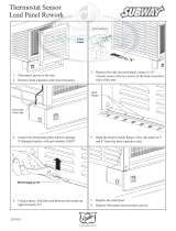
4.7.2. Models 0181-0401 and 0182-0400
1. Shut-off main electrical power switch to boiler.
2. Turn heater manual switch located in upper control
panel to the “OFF” position.
3. Shut-off gas supply and water supply to the boiler.
4. Mount drafthood on top of boiler as shown in Figure
10. Drafthood should be positioned with the vent
sensor located on the front right side as shown.
5. Remove plastic plug from left side of boiler jacket
and install plastic grommet provided.
6. Route flue sensor wire harness through the grommet
installedinStep5(Models0181-0261).
Figure 10. Boiler After Drafthood Installation for Models
0181-0401 and 0182-0400
7. Remove door and locate wire from roll-out sensor to
high limit with the male/female connector.
8. Disconnect male/female connector and attach to
the 2 wires from drafthood vent sensor harness.
4.7.3. Models 0514-0824
Locate and assemble as shown in Figure 11. Secure with
screws supplied in envelope in carton.
Figure 11. Drafthood Installation for Models 0514–0824
4.7.4. Models 0962-1826
Locate and assemble as shown in Figure 12. Secure with
screws supplied in envelope in carton.
Figure 12. Drafthood Installation for Models 0962–1826
4.7.5. Models 2100-4001
These models have built-in drafthoods. For proper
operation, the drafthood outlet must be connected to the
venting system.

11
As much as possible, avoid long horizontal runs of vent pipe
and too many elbows. If installation requires horizontal
non-vertical runs, the vent pipe must have a minimum of
1/4 inch per foot rise and should be supported at not more
than5'(1.5m)intervals.Plumberstape,criss-crossed,will
serve to space both horizontal and vertical piping.
Gasventssupportedonlybytheashingandextending
above the roof more than 5' (1.5 m) should be securely
guyed or braced to withstand snow and wind loads.
Raypak recommends the use of insulated vent pipe
spacers through the roof and walls.
For protection against rain or blockage by snow, the vent
pipe must terminate with a vent cap which complies with
the local codes or, in the absence of such codes, to the
latest edition of the National Fuel Gas Code, ANSI Z223.1.
Thedischargeopeningmustbeaminimumof2'(0.6m)
verticallyfromtheroofsurfaceandatleast2'(0.6m)higher
than any part of the building within 8' (2.4 m) for vents
smaller than 12" (305 mm) diameter. For 12" (305 mm)
diameter vents and larger, the termination must be
2' (0.6 m) higher than any part of the building within
10'(3m).SeeFigure 14.
VENT CAP
LESS THAN 12" (305 mm) DIA VENT - WITHIN 8' (2.4 m)
12" (305 mm) OR LARGER DIA VENT - WITHIN 10' (3 m)
*(SEE VENT PIPING INSTRUCTIONS)
*
2' MIN
(610 mm)
VENT PIPE
DRAFT HOOD
5' MIN
(1.5 m)
HEATER
2' MIN
(610 mm)
Figure 14. Venting Clearances
Vent stack shall be at least 5' (1.5 m) in vertical height
above the drafthood outlet. The vent cap location shall
have a minimum clearance of 4' (1.2 m) horizontally
from,andinnocaseaboveorbelow,unlessa4'(1.2m)
horizontal distance is maintained, from electric meters,
gasmetersregulatorsandreliefequipment.
4.8. Vent Piping
AA
WARNING: Indoor boilers require a drafthood that
must be connected to a vent pipe and properly vented to
the outside. Failure to follow this procedure can cause
4.8.1. Appliance Categories
Heaters are divided into four categories based on the
pressure produced in the exhaust and the likelihood of
condensate production in the vent.
Category I – A heater which operates with a non-positive
vent static pressure and with a vent gas temperature that
avoidsexcessivecondensateproductioninthevent.
Category II – A heater which operates with a non-positive
vent static pressure and with a vent gas temperature that
maycauseexcessivecondensateproductioninthevent.
Category III – A heater which operates with a positive
vent pressure and with a vent gas temperature that avoids
excessivecondensateproductioninthevent.
Category IV – A heater which operates with a positive vent
pressure and with a vent gas temperature that may cause
excessivecondensateproductioninthevent.
AA
WARNING: Examine the venting system at least once
a year. Check all joints and vent pipe connections for
tightness, corrosion or deterioration.
Vent piping the same size or larger than the drafthood
outlet is recommended, however, when the total vent
heightisatleast10'(3m)(drafthoodreliefopeningtovent
terminal),theventpipesizemaybereducedasspecied
in Chapter 10 of the latest edition of the National Fuel Gas
Code(NFGC),ANSIZ223.1.
These units are certied for operation with cat I vents
(naturaldraftconditions).Refertothestandardventtables
in NFGC.
Figure 13. Common Venting

12
The weight of the vent stack or chimney must not rest on
boiler drafthood. Support must be provided in compliance
with applicable codes. The boiler top and drafthood must
be readily removable for maintenance and inspection.
Vent pipe should be adequately supported to maintain
proper clearances from combustible construction.
Type “B” double-wall or equivalent vent pipe is
recommended. However, single-wall metal vent pipe may
beusedasspeciedinthelatesteditionoftheNFGC.
Manifolds that connect more than one boiler to a common
chimney must be sized to handle the combined load.
Consult available guides for proper sizing of the manifold
and the chimney. At no time should the area be less than
the area of the largest outlet.
Atthetimeofremovalofanexistingboiler,thefollowing
steps shall be followed with each appliance remaining
connected to the common venting system placed
in operation, while the other appliances remaining
connected to the common venting system are not in
operation.
a. Seal any unused openings in the common
venting system.
b. Visually inspect the venting system for proper
size and horizontal pitch and make sure there
is no blockage or restriction, leakage, corrosion
and other deficiencies which could cause an
unsafe condition.
c. As much as possible, close all building doors
and windows and all doors between the space
in which the appliances remaining connected
to the common venting system are located and
other spaces of the building. Turn on clothes
dryers and any appliance not connected to the
common venting system. Turn on any exhaust
fans, such as range hoods and bathroom
exhausts, so they will operate at maximum
speed. Do not operate a summer exhaust fan.
Close fireplace dampers.
d. Place in operation the appliance being
inspected. Follow the lighting instructions.
Adjust thermostat so appliance will operate
continuously.
e. Test for spillage at the drafthood relief opening
after 5 minutes of main burner operation. Use
the flame of a match or candle, or smoke from a
cigarette, cigar or pipe.
f. After it has been determined that each appliance
remaining connected to the common venting
system properly vents when tested as outlined
above, return doors, windows, exhaust fans,
fireplace dampers and any other gas burning
appliance to their previous conditions of use.
g. Any improper operation of the common
venting system should be corrected so that the
installation conforms with the latest edition
of the NFGC. When re-sizing any portion of
the common venting system, the common
venting system should be re-sized to approach
the minimum size as determined using the
appropriate tables in Chapter 13 of the NFGC.
Forspecialventingapplicationsthatrequirereducedvent
sizes, or through-the-wall venting, the Type D Induced
Draft Assembly can be used. Consult the factory or your
local Raypak representative.
4.9. Vent Damper Installation
(Models 0181 Through 0261) Where Required
Location
The vent damper must be located in the vent so that it
serves only the appliance for which it is intended.
If improperly installed, a hazardous condition, such as an
explosion or carbon monoxide poisoning, could result.
Make certain that it is mounted in an accessible location
at least 6" (152 mm) from any combustible material or
theheatexchanger,andthatthepositionindicatorisina
visible location.
The vent damper must be installed after the appliance
drafthood, as close to the drafthood as practicable, and
withoutmodicationofthedrafthood.
Figure 15. Vent Damper Installation on Drafthood
AA
WARNING: Do not use thermally actuated vent
dampers on a modulating boiler. To do so may result in
asphyxiation. Use only a mechanically actuated vent
damper device that is electrically interlocked with the
modulating boiler operation.

13
On vertical vents, the vent damper may be mounted with
the actuator in any position. On horizontal vents, do not
mount the actuator either directly above or directly below
the vent pipe; mount the vent damper actuator to the side
of the vent.
The vent damper ships set up for a continuous pilot system.
SincetheRaythermisequippedwithanIntermittentPilot,
the hole in the vent damper blade must be plugged using
the knockout plug, Part No. 105612R, provided in the
parts envelope.
HORIZONTAL INSTALLATION
TO BOILER
D80B TO CHIMNEY
NO
NO
YES
YES
VERTICAL
INSTALLATION
TO CHIMNEY
VENT DAMPER
TO BOILER
INSTALL VENT DAMPER
WITH ACTUATOR TO
SIDES OF VENT ONLY.
DO NOT MOUNT ABOVE
OR BELOW VENT.
FLOW >
ACTUATOR MAY BE
INSTALLED IN ANY
POSITION ON VERTICAL
PIPE
Figure 16. Horizontal/Vertical Vent Damper Installation
D80B
N. O.
N. C.
END
SWITCH
C.
1K2
1K1
R
1K3
1
2
3
4
5
1R
BLACK
ORANGE RED YELLOW BLUE
THERMOSTAT OR
CONTROLLER
LIMIT
OPTIONAL LIMIT
LOCATION
TRANSFORMER
DUAL VALVE
COMBINATION
GAS CONTROL OR
IGNITION SYSTEM
1
1
L1
L2
(HOT)
POWER SUPPLY PROVIDE DISCONNECT MEANS AND OVERLOAD PROTECTION AS REQUIRED
Figure 17. Vent Damper General Wiring Diagram
AA
CAUTION: Install the vent damper to service only the
single appliance for which it is intended. If improperly
installed, a hazardous condition, such as an explosion or
carbon monoxide poisoning, could result.
4.9.1. Vent Damper
Normal Operation Summary
Forsafe,ecientoperation,theventdamperandallue
product carrying areas of the appliance must be checked
annually, with particular attention given to deterioration
from corrosion or other sources. Check vent damper
operation as follows:
1. When the boiler is off, check that the vent damper
position indicator points to the closed position. See
Figure 19.
2. Turn the thermostat or controller up to call for heat
and check that the vent damper indicator points to
the open position. See Figure 19.
3. Turn the thermostat or controller down again and
check that the vent damper position indicator returns
to the closed position.
NOTE: The vent damper must be inspected at least once a
year by a trained, experienced service technician. Damper
must be in open position when boiler main burners are
operating.
Figure 18. Vent Damper Position Indicator
Figure 19.

14
4.10. Gas Supply Connections
Gas piping must have a sediment trap ahead of the boiler
gascontrols,andamanualshut-ovalvelocatedoutside
the heater jacket. All gas piping should be tested after
installation in accordance with local codes.
Figure 20. Plumbing
A minimum of 7.0" W.C. upstream gas pressure under full
loadandamaximumgassupplypressuresetpointof10.5"
W.C. under load and no-load conditions for natural gas.
A minimum of 12.0" W.C. upstream gas pressure under
full load and a maximum gas supply pressure of 13.0"
W.C. is required for propane gas. If upstream pressure
exceeds1/2psiatanytime,anintermediategaspressure
regulator, of the lockup type, must be installed.
NOTE: Only sealant tape or a pipe compound rated for
use with natural and propane gases is recommended.
Apply sparingly only on male pipe ends, leaving the two
end threads bare.
AA
CAUTION:
be disconnected from the gas supply during any pressure
testing of that system at test pressures in excess of 1/2
PSIG. Dissipate test pressure in the gas supply line before
gas supply line. FAILURE TO FOLLOW THIS PROCEDURE
MAY DAMAGE THE GAS VALVE. OVER-PRESSURED
GAS VALVES ARE NOT COVERED BY WARRANTY. The
boiler and its gas connections shall be leak tested before
placing the appliance in operation. Use soapy water for
4.11. Gas Pressure Regulator
The manifold gas pressure regulator is preset nominally at
4" W.C. for natural gas, and 11" W.C. for propane. Between
the gas valve and the burners is a 1/8" pipe plug. The
pressure at this point, taken with a manometer, should be
about 3.7" W.C. for natural gas and 10.5" W.C. for propane.
Low NOx models should be 3.9" W.C., natural gas only.
If an adjustment is needed, turn adjustment screw
clockwise to increase pressure, or counter-clockwise to
decrease pressure.
Forboilerswithmechanicalmodulationgasvalves(Type
H1 and H5) or two-stage gas valves (Type H3), the gas
pressure regulator is preset and sealed, and not eld
adjustable. Pressure tap is provided on the outlet side
of the gas valve for measurement of gas pressure in the
manifold.
4.12. Venting of Diaphragm
Gas Components
Gasvalvesthat areequipped with a gas bleedmust be
vented totheoutdoorsasrequiredbytheNationalFuel
Gas Code. Under NO circumstances shall bleed lines
terminateinthegasutilizationequipmentueorexhaust
system.
BLEED LINE
CONNECTION
VENT LINE
CONNECTION
Figure 21. Bleed Line Connection Location
4.12.1. General
Boiler should be located so that any water leaks will not
cause damage to any adjacent areas or structures. See
piping diagrams for proper water connections for the type
of boiler and system.
4.12.2. Pump Selection
In order to ensure proper hydraulics in your hydronic
heating system, adequate pump size must be selected.
Raypakrecommendsthatthepumpbesizedfor20°F(-7°C)
Delta-T whenever possible. (Delta-T is the temperature
dierence between the inlet and outlet waterwhen the
boiler is ring at full rate). Forsome boilers, the Delta-T
is more than 20°F (-7°C) [22°F (-6°C) - 33°F (1°C)] at the
recommendedowrates.

15
Model No.
NPT
NPT
NPT
N P N P N P N P N P N P N P N P N P
0182*
0181**
15
(5)
30
(9)
65
(20)
95
(29)
250
(76)
400
(122)
0260*
0261**
10
(3)
20
(6)
40
(12)
60
(18)
140
(43)
250
(76)
560
(171)
0330*
0331**
15
(5)
25
(8)
35
(11)
85
(26)
150
(46)
380
(116)
360
(110)
0400*
0401**
15
(5)
25
(8)
60
(18)
100
(30)
260
(79)
250
(76)
0514
10
(3)
15
(5)
35
(11)
65
(20)
150
(46)
130
(40)
360
(110)
500
(152)
0624
10
(3)
25
(8)
45
(14)
100
(30)
95
(29)
250
(76)
340
(104)
0724
20
(6)
35
(11)
80
(24)
75
(23)
180
(55)
260
(79)
600
(183)
0824
15
(5)
25
(8)
60
(18)
55
(17)
130
(40)
185
(56)
480
(146)
500
(152)
0926/0962
15
(5)
20
(6)
45
(14)
45
(14)
110
(34)
150
(46)
360
(110)
400
(122)
1083/1125
10
(3)
15
(5)
35
(11)
35
(11)
80
(24)
120
(37)
300
(91)
300
(91)
1178/1223
25
(8)
25
(8)
60
(18)
85
(26)
220
(67)
200
(61)
1287/1336
25
(8)
20
(6)
55
(17)
75
(23)
180
(55)
170
(52)
325
(99)
560
(171)
1414/1468
20
(6)
15
(5)
45
(14)
65
(20)
150
(46)
165
(50)
300
(91)
500
(152)
1571/1631
15
(5)
15
(5)
35
(11)
50
(15)
120
(37)
125
(38)
250
(76)
400
(122)
1758/1826
15
(5)
10
(3)
30
(9)
40
(12)
100
(30)
100
(30)
225
(69)
340
(104)
2100
10
(3)
10
(3)
25
(8)
30
(9)
80
(24)
75
(23)
175
(53)
260
(79)
2500
15
(5)
20
(6)
55
(17)
55
(17)
135
(41)
160
(49)
400
(122)
600
(183)
3001
10
(3)
15
(5)
35
(11)
40
(12)
85
(26)
120
(37)
250
(76)
500
(152)
3500
10
(3)
30
(9)
30
(9)
45
(14)
80
(24)
200
(61)
400
(122)
600
(183)
4001
5
(2)
20
(6)
25
(8)
35
(11)
65
(20)
160
(49)
300
(91)
400
(122)
Natural gas - 1,000 btu/ft
3
, 0.60 specific gravity at 0.5" W.C. pressure drop
Propane gas - 2,500 btu/ft
3
, 1.53 specific gravity at 0.6" W.C. pressure drop
Lengths based on Sched 40 BIP - for other materials consult local codes
* Models NOT available for propane
**LowNOxModels
Table F. Maximum Equivalent Pipe Length (ft./m)

16
Model No.
2-PASS HEAT EXCHANGER 1-PASS HEAT EXCHANGER
MAX MIN
HDR
CONN
MAX MIN
HDR
CONN
GPM
(lpm)
FT.
GPM
(lpm)
FT.
GPM
(lpm)
GPM
(lpm)
FT.
0182*/0181** 45(170) 7 9.2 20(76) 15 1.8 1-1/2”
0260*/0261** 45(170) 10 9.4 20(76) 22 1.9 1-1/2”
0330*/0331** 45(170) 12 9.6 20(76) 28 1.9 1-1/2”
0400*/0401** 45(170) 15 9.8 20(76) 33 2.0 1-1/2”
514 90(341) 9 9.0 40(152) 21 1.8 2”
624 90(341) 12 9.5 40(152) 26 1.9 2”
724 90(341) 13 10.0 40(152) 30 2.0 2”
824 90(341) 15 10.5 40(152) 34 2.1 2”
926 90(341) 17 11.0 40(152) 38 2.2 2-1/2” 200(758) 8 9.7 90(341) 17 2.1 3”
962 90(341) 18 11.0 40(152) 40 2.2 2-1/2” 200(758) 8 9.7 90(341) 18 2.1 3”
1083 90(341) 20 12.0 45(170) 40 3.1 2-1/2” 200(758) 9 10.3 90(341) 20 2.3 3”
1125 90(341) 21 12.0 47(178) 40 3.3 2-1/2” 200(758) 9 10.3 90(341) 20 2.3 3”
1178 90(341) 22 12.5 49(186) 40 3.8 2-1/2” 200(758) 10 11 90(341) 21 2.4 3”
1223 90(341) 22 12.5 51(193) 40 4.0 2-1/2” 200(758) 10 11 90(341) 22 2.4 3”
1287 90(341) 24 13.2 53(201) 40 4.5 2-1/2” 200(758) 11 11.7 90(341) 23 2.5 3”
1336 90(341) 24 13.2 55(208) 40 4.9 2-1/2” 200(758) 11 11.7 90(341) 24 2.5 3”
1414 90(341) 26 14.0 58(220) 40 5.8 2-1/2” 200(758) 12 12.2 90(341) 26 2.7 3”
1468 90(341) 27 14.0 61(231) 40 6.4 2-1/2” 200(758) 12 12.2 90(341) 27 2.7 3”
1571 90(341) 29 14.5 65(246) 40 7.5 2-1/2” 200(758) 13 13 90(341) 29 2.8 3”
1631 90(341) 30 14.5 68(258) 40 8.3 2-1/2” 200(758) 13 13 90(341) 30 2.8 3”
1758 90(341) 32 15.4 73(277) 40 10.0 2-1/2” 200(758) 14 14.7 90(341) 32 3.0 3”
1826 90(341) 34 15.4 76(288) 40 10.8 2-1/2” 200(758) 15 14.7 90(341) 33 3.0 3”
2100 200(758) 17 14.8 90(341) 39 3.2 3” 400(1515) 9 18
180
(682)
19 4.0 4”
2500 200(758) 21 15.8 103(390) 40 4.4 3” 400(1515) 10 18.8
180
(682)
23 4.1 4”
3001 200(758) 25 16.7 124(470) 40 6.7 3” 400(1515) 12 19.5
180
(682)
27 4.3 4”
3500 200(758) 29 17.5 145(549) 40 9.5 3” 400(1515) 14 20.5
180
(682)
32 4.5 4”
4001 200(758) 33 18.7 166(629) 40 13.0 3” 400(1515) 16 21.5
180
(682)
36 4.7 4”
GPMFlowrateslimitedbymaximumacceptablevelocitythroughheatexchangertubes.Maybeincreasedby10%forclosedheatingsystems.
* Models NOT available for propane
**LowNOxModels
Table G. Maximum and Minimum Flow Rates

17
4.12.3. Feedwater Regulator
Raypak recommends that a feedwater regulator be
installed and set at 12 PSIG minimum pressure. Install a
checkvalveorbackowdeviceupstreamoftheregulator,
withamanualshut-ovalve.Leavethevalveopen.
4.12.4. Piping - Heating Boilers
Raypak recommends that all high points be vented and
that purge valves and a bypass valve be installed. A boiler
installed above radiation level must be provided with a low-
watercut-odevice.Theboiler,whenusedinconjunction
with a refrigeration system, must be installed so that the
chilled medium is piped in parallel with the boiler with
appropriate valves to prevent the chilled medium from
entering the boiler.
Raypak strongly recommends the use of primary/
secondary piping for all H boilers, as shown in the
followingpipingdiagrams.Systemowmustexceedthe
owthroughtheboileratallringrates.
Hot water heating systems all have unique levels of
operating diversity that must be accounted for in the
system design. The system should always include
adequatesystemowinexcessoftheconnectedboiler
ow for proper operation. Where the system ow may
dropbelowtheconnectedboilerowabuer/decoupler
maybeneeded.Failuretodesignforadequateow(i.e.
bypasses, 3 way control valves, ow limiting balance
devices, buer tanks, etc.) will result in boiler short-
cycling and may reduce boiler life. Always contact your
local Raypak representative for system design assistance
to avoid these issues.
Min 105°F (41°C) water temp at the inlet to avoid
condensation.
4.12.5. Recommended Purge Manifolds
for Typical Hydronic System
Hookups
The boiler piping system of a hot water heating boiler
connected to heating coils located in air handling units
wheretheymaybeexposedtorefrigeratedaircirculating,
must be equipped with ow control valves or other
automatic means to prevent gravity circulation of the
boiler water during the cooling cycle.
4.12.6. Temperature and Pressure Gauge
The temperature and pressure gauge is standard
equipmentonallhydronicheatingandhotwatersupply
boilers. All temperature and pressure gauges are factory
mountedinthein/outheaderexceptforresidentialboilers,
Models 0181-0401. On these models the temperature and
pressuregaugeisshippedlooseforeldinstallation,and
locatedintheoutletwaterconnection.Allttingsrequired
to mount gauge to piping system are supplied by others.
5. CONTROLS
5.1. Economaster Controls
The Economaster II is an electronic device that allows the
operator to set the desired time for the pump to run after
theboilershutso. Thetime is factory-set at7 minutes
anditcanbere-adjustedintheeldanywherefrom3to
10 minutes.
Inaconventionalsystem,whentheaquastatissatised,
the main gas valve closes, but the pump continues
operating. With the energy-conserving Economaster II
the boiler pump is programmed to continue running for
an optimum period of time in order to absorb the residual
heat from the combustion chamber and use it in the
system. The pump then shuts o until the next call for
heatisreceivedfromtheaquastat.
NOTE:
boiler.
NOTE: Boiler pump delay is built into the Outdoor Air
5.2. Electronic Ignition
The intermittent ignition device conserves energy by
automatically extinguishing the pilot when desired
temperature is reached. When additional heat is needed,
the pilot re-ignites electrically, eliminating the fuel costs
of maintaining a constant pilot. To ensure safe operation,
the gas valve cannot open until the pilot relights and is
proven.
Models 0181-0401, when built to operate on natural gas,
areequippedwithacontinuousretrypilotignitionmodule
as standard. Propane units, as well as all 0514-4001 units
regardless of fuel type, are equipped with a 90-second
trial for pilot ignition - lockout ignition module as standard.
Figure 22. Economaster PCB

18
LOCATE BUFFER TANK
HERE (IF REQUIRED)
SEE CAT. NO. 2000.82
4 PIPE DIAS
OR 12” MAX
MINIMUM SYSTEM FLOW =
BOILER FLOW + 15%
NOTE: EXPANSION TANKS (SUPPLIED BY OTHERS)
SHOULD BE INSTALLED PER MANUFACTURER’S INSTRUCTIONS.
Figure 23. Single Boiler Primary/Secondary Piping - Models 181–4001
MAXIMUM OF 12” OR
4 PIPE DIAMETERS
CONTROLLER
SENSOR
5’ MAX
LOCATE BUFFER TANK
HERE (IF REQUIRED)
SEE CAT. NO. 2000.82
MINIMUM SYSTEM FLOW =
BOILER FLOW + 15%
REVERSE RETURN PIPING IS A PROPER METHOD
OF MANIFOLDING MULTIPLE BOILER HOOK-UPS
TO ENSURE BALANCED FLOW THROUGH EACH
BOILER. VALVES ON SUPPLY AND RETURN ARE
NEEDED TO ISOLATE ANY BOILER, AS REQUIRED.
Figure 24. Multiple-Boiler - Reverse Return Hook-Up - Models 181–4001

19
5.3. Outdoor Air Reset
Temperature Controller
Models0181through0261arefactory-equippedwithan
electronic outdoor air reset temperature controller. This
controller is also an available option for models 0330
through 0401.
Thestandardcongurationprovidesforoutdoorairreset
of the system target water temperature based on a user-
denedresetratio.Thecontrollerwillresetbetween120°F
(49°C)systemwatertemperatureanda maximumboiler
outlet of 210°F (99°C). The controller will provide two-
stageringoftheheater.Thecontrollerisalsoequipped
with a connection for an external thermostat input for
use with an indirect load such as an indirect DHW tank
for hot water production. When used for direct DHW in
conjunction with a storage tank, the controller can be
conguredtoprovidexedsetpointoperation.
The system sensor has 1/4" NPT connection
conversion and ships standard in the inlet header. The
primary functions of the controller are set using the
Operating Temperature dial and the DIP switches. See
Table I.
The controller has 4 LEDs to indicate the its condition:
Power - On Solid - Turns on when 24 Vac Power
is present.
Heat Call - On Solid - Turns on when Heat Call
(shortor0-32Vac)ispresent.
Flashing - Boiler outlet sensor error.
While present, operation ceases.
IND Call - On Solid - Turns on when IND Call
(shortor0-32Vac)ispresent.
Flashing - System supply sensor error.
While present, operation continues using
boiler outlet sensor.
WWSD - On Solid - Turns on when in Outdoor
Reset AND WWSD Active AND control
in WWSD.
Flashing - Outdoor sensor error. While
present, operation continues with Fixed
boilertargettempof140°F(60°C)based
on32°F(0°C)air.
5.4. Hydronic with Outdoor Air Reset
For hydronic operation with outdoor air reset, the System
SupplySensor(S2)isusedastheoperatingsensor.Boiler
Outlet Sensor (S1) is used for boiler outlet maximum
limiting.BoilerPump(P1)iscontrolledbytheboilerandis
cycledousinga5minutexedpurgedelayafterburner
operation has ceased.
The DIP switch settings are as follows:
DIP1 ON(ON/OFF)–OFF(2-STAGE)
DIP2 ON(OUTDOORRESET)
DIP3 ON(WWSD70°F)
DIP4 ON(190°FBOILMAX)
DIP5 ON(HYDRONIC)
S1
S3
P1
S2
Figure 25. Hydronic with Outdoor Air Reset

20
5.5. Hydronic, Outdoor Air
For hydronic operation with outdoor air reset and Indirect
DHW, the System Supply Sensor (S2) is used as the
operating sensor. Boiler Outlet Sensor (S1) is used for
boileroutletmaximumlimiting.Contactclosurefroman
aquastatlocatedonanindirectDHWtankwillcausethe
controller to operate to a boost temperature to satisfy
the indirect call for heat. Once the aquastat opens the
controller will return to normal operation.
The indirect pump is operated by an external relay (by
others).The Boiler Pump (P1) is controlled by the boiler
andiscycledousinga5minutexedpurgedelayafter
burner operation has ceased.
The DIP switch settings are as follows:
DIP1 ON(ON/OFF)–OFF(2-STAGE)
DIP2 ON(OUTDOORRESET)
DIP3 ON(WWSD70°F)
DIP4 ON(190°FBOILMAX)
DIP5 ON(HYDRONIC)
Figure 26. Hydronic with Outdoor Air Reset and Indirect DHW
S1
S3
A1
P1
S2
Item Feature Setting/Description Default
Dial
Operating
Temperature
Reset Ratio 0.4 to 3.6 / Setpoint Target 120F to 200F Reset Ratio 0.4 to 3.6
DIP #1 Firing Mode SingleStage(On)/TwoStage(O) SingleStage(On)
DIP #2 Conguration OutdoorReset(On)/Setpoint(O) OutdoorReset(On)
DIP #3
Warm Weather
Shut Down
Active70°F(21°C)(On)/Inactive(O)
Active70°F(21°C)
(On)
DIP #4
BoilerMax
Outlet Setting
BoilerMaximum(dependentonDIP#5)-Default:On
o if DIP #5 set to Hydronic (On): 210°F (99°C) (O) / 190°F (88°C) (On)
o if DIP #5 set to Direct DHW (O): 180°F (82°C) (O) / 160°F (71°C) (On)
190°F(88°C)(On)
DIP #5
Space Heating
or Direct
Domestic Hot
Water
DirectDHW(O)/Hydronic(On)-Default:Hydronic(On)
Note: if DIP #5 is set to Direct DHW (O), the operation is based on
Setpoint regardless of DIP #2 setting
Hydronic(On)
Table H. Outdoor Air Reset Temperature Controller Settings
/