Page is loading ...


2
SAFETY INFORMATION
SAFETY WARNINGS

3
USING THIS MANUAL
USING THIS MANUAL
n
WARNINGS
• THIS UNIT IS FOR CATEGORY IV VENTING - 2 PIPE ONLY. THIS IS A SEALED
COMBUSTION APPLIANCE.
• THIS HEATER INSTALLATION MUST CONFORM TO THE LATEST EDITION OF THE
“NATIONAL FUEL GAS CODE” ANSI Z223.1 NEPA 54 AND OR CAN/CGA B149
INSTALLATION CODES. STATE AND LOCAL CODES MIGHT ALSO APPLY TO
INSTALLATION.
• WHERE REQUIRED BY THE AUTHORITY HAVING JURISDICTION, THE
INSTALLATION MUST CONFORM TO THE STANDARDS FOR CONTROLS AND
SAFETY DEVICES FOR AUTOMATICALLY FIRED HEATERS, ANSI/ASME HEATER
AND PRESSURE VESSEL CODE, Section IV, ALONG WITH CSD1.
• THE HEATER, GAS PIPING, WATER PIPING, VENTING AND ELECTRICAL MUST BE
INSTALLED BY TRAINED & QUALIFIED PERSONNEL FAMILIAR WITH
INSTALLATION PRACTICES, LOCAL CODE, LICENSING REQUIREMENTS.
• IF THE INFORMATION IN THESE INSTRUCTIONS ARE NOT FOLLOWED EXACTLY,
A FIRE OR EXPLOSION MAY RESULT; CAUSING PROPERTY DAMAGE, PERSONAL
INJURY, OR DEATH.
• DO NOT STORE OR USE GASOLINE OR OTHER FLAMMABLE VAPORS AND
LIQUIDS IN THE VICINITY OF THIS OR ANY OTHER APPLIANCE;
• THE USE OF A LOW WATER CUT-OFF DEVICE MAY BE REQUIRED BY STATE OR
LOCAL CODES IF THE MUNCHKIN IS INSTALLED ABOVE RADIATION LEVELS.
n
WARNING
If the information in this manual is not followed exactly, a fire or explo-
sion may result causing property damage, personal injury or loss of life.
Do not store or use gasoline or other flammable vapors and liquids in the
vicinity of this or any other appliance.
WHAT TO DO IF YOU SMELL GAS
• Do not try to light any appliance.
• Do not touch any electrical switch: do not use any phone in your
building.
• Immediately call your gas supplier from a neighbor's phone. Follow
the gas supplier's instructions.
• If you cannot reach your gas supplier, call the fire department.
Installation and service must be performed by a qualified installer,
service agency or the gas supplier.
• Installation and service must performed by a qualified installer, service
agency or gas supplier.

4
TABLE OF CONTENTS
TABLE OF CONTENTS
PART 1 . . . . . . . . . . . . . . . . . . . . . .5 thru 9
GENERAL INFORMATION
A How It Operates . . . . . . . . . . . . . . . . . .5
B Munchkin Ratings and Dimensions . .6–7
C Pre-installation Requirements . . . . . . .8
D Pressure Relief Valve . . . . . . . . . . . . . .9
PART 2 . . . . . . . . . . . . . . . . . . . . .9 thru 10
ELECTRICAL
A Electrical Connection . . . . . . . . . . . . . .9
PART 3 . . . . . . . . . . . . . . . . . . . .10 thru 11
GAS CONNECTION
A Gas Connection . . . . . . . . . . . . . . . . . .10
B Gas Piping . . . . . . . . . . . . . . . . . . . . . .11
C Gas Table . . . . . . . . . . . . . . . . . . . . . . .11
D Gas Valve Conversion . . . . . . . . . . . . .11
PART 4 . . . . . . . . . . . . . . . . . . . .12 thru 18
VENTING
A General . . . . . . . . . . . . . . . . . . . . . . . .12
B Approved Venting Materials for
Exhaust Vent and Intake Air Pipe . . . .12
C Exhaust/Vent / Air Intake Pipe
Location . . . . . . . . . . . . . . . . . . . . . . .12
D Exhaust Vent and Intake Air Pipe
Sizing . . . . . . . . . . . . . . . . . . . . . . . . . .15
E Exhaust Vent and Air Intake Pipe
Installation . . . . . . . . . . . . . . . . . . . . . .15
F Heater Removal from a Common
Vent System . . . . . . . . . . . . . . . . . . . .16
G Condensate Removal . . . . . . . . . . . . .16
PART 5 . . . . . . . . . . . . . . . . . . . .19 thru 29
PIPING
A Expansion Tank . . . . . . . . . . . . . . . . . .19
B High Velocity Circulator Pump . . . . . .19
C Circulator Sizing . . . . . . . . . . . . . . . . .20
PART 6 . . . . . . . . . . . . . . . . . . . .30 thru 34
START UP PROCEDURES
A Sequence of Operation . . . . . . . . . . .30
B Items to be Checked Before
Lighting the Munchkin . . . . . . . . . . . .31
C Lighting Instructions . . . . . . . . . . . . . .31
D Operating Instructions . . . . . . . . . . . .31
E Adjusting the Operating Set Points
of the Munchkin VWH Display . . . . . .32
F Status Menu . . . . . . . . . . . . . . . . . . . .32
G Test Mode . . . . . . . . . . . . . . . . . . . . . .33
H To Turn Off Gas to Appliance . . . . . . .33
PART 7 . . . . . . . . . . . . . . . . . . . .35 thru 37
TROUBLESHOOTING
A Munchkin Error Code . . . . . . . . . . . . .35
B Boiler Error . . . . . . . . . . . . . . . . . . . . .35
C Boiler Fault . . . . . . . . . . . . . . . . . . . . .35
PART 8 . . . . . . . . . . . . . . . . . . . .38 thru 45
MAINTENANCE
A Maintenance Procedures . . . . . . . . . .38
B Annual Maintenance . . . . . . . . . . . . . .38
C Condensate Cleaning Instructions . . .38
D Combustion Chamber
Coil Cleaning Instructions . . . . . . . . . .39
E Munchkin Controllers . . . . . . . . . . . . .41

5
GENERAL INFORMATION
RECOMMENDED SERVICE CLEARANCES
PART 1. GENERAL INFORMATION
A. HOW IT OPERATES
The Munchkin VWH is a hot water supply boiler designed to operate in conjuction with a hot water
storage tank. Each Munchkin VWH is equipped with a high velocity pump to keep the unit running
efficiently for many years of service. A flow switch monitors the water flow through the heat exchanger
to make sure that the unit has an adequate flow rate during operation. The Munchkin VWH Controller
accurately monitors the return and supply temperature that controls the output range of the Munchkin
When the system has sensed a temperature drop below the set point and minus the differential set
point, The Munchkin VWH will activate the blower motor for a pre-purge of 5 seconds before going
into operation. Once in operation, the Munchkin controller will now start to modulate the pre-mix
burner based on analyzing the return, supply, differential and operating set point temperatures. By
compiling this information, the controller utilizes an algorithm to fully adjust the firing rate while
maintaining the desired output temperature. The pre-mix burner fan has direct drive current, low-
voltage motor with pulse relay counting. This system allows precise control over the fan speed and
combustion air volumes. Coupled with the fuel and air mixing system which are set to provide a one
to one ratio of precisely measured volumes of fuel to air, an accurate and instant burner output is
achieved. This keeps the Munchkin VWH running at the highest efficiency.
RECOMMENDED SERVICE CLEARANCES
Figure 1-1
SPECIAL ATTENTION BOXES
Throughout this manual you will see these
special attention boxes similar to this one,
which are intended to supplement the
instructions and make special notice of
potential hazards. These categories mean, in
the judgement of Heat Transfer Products, Inc.:
n
DANGER
DANGER indicates an imminently hazardous
situation which, if not avoided, will result in
death or serious injury.
n
WARNING
WARNING indicates a potentially hazardous
situation which, if not avoided, could result in
death or serious injury.
n
CAUTION
CAUTION Indicates a potentially hazardous
situtation which, if not avoided, may result in
minor or moderate injury.
CAUTION
CAUTION used without the safety alert symbol
indicates a potentially hazardous situation which,
if not avoided, may result in property damage.

6
GENERAL INFORMATION
B. MUNCHKIN RATINGS AND DIMENSIONS
MODEL INLET OUTLET RECOVERY RATE
FIRST HOUR RATING
W/ 80 GAL. STORAGE TANK
FIRST HOUR RATING
W/ 119 GAL. STORAGE TANK
199 VWH 40° 80° 573 GPH 626 GAL 652 GAL
199 VWH 40° 90° 458 GPH 511 GAL 537 GAL
199 VWH 40° 100° 382 GPH 435 GAL 461 GAL
199 VWH 40° 110° 327 GPH 380 GAL 406 GAL
199 VWH 40° 120° 287 GPH 340 GAL 366 GAL
199 VWH 40° 130° 255 GPH 308 GAL 334 GAL
199 VWH 40° 140° 229 GPH 282 GAL 308 GAL
199 VWH 40° 150° 208 GPH 261 GAL 287 GAL
199 VWH 40° 160° 191 GPH 244 GAL 270 GAL
199 VWH 40° 170° 176 GPH 229 GAL 255 GAL
199 VWH 40° 180° 163 GPH 216 GAL 242 GAL
399 VWH 40° 80° 1149 GPH 1202 GAL 1228 GAL
399 VWH 40° 90° 919 GPH 972 GAL 998 GAL
399 VWH 40° 100° 766 GPH 819 GAL 845 GAL
399 VWH 40° 110° 657 GPH 710 GAL 736 GAL
399 VWH 40° 120° 575 GPH 628 GAL 654 GAL
399 VWH 40° 130° 510 GPH 563 GAL 589 GAL
399 VWH 40° 140° 460 GPH 513 GAL 539 GAL
399 VWH 40° 150° 418 GPH 471 GAL 497 GAL
399 VWH 40° 160° 383 GPH 436 GAL 462 GAL
399 VWH 40° 170° 354 GPH 407 GAL 433 GAL
399 VWH 40° 180° 328 GPH 381 GAL 407 GAL
199 VWH at 20GPM
Pressure Drop for Tube Length of 1¼” Copper
(10) 90° Elbows ad (2) Tees (Side Outlet)
with Munchkin 199 VWH
1¼” Tube Length 20’ 30’ 40’ 50’ 60’
20 GPM 21.65 22.62 23.6 24.56 25.53
399 VWH at 40GPM
Pressure Drop for Tube Length of 2” Copper
(10) 90° Elbows and (2) Tees (Side Outlet)
with Munchkin 399 VWH
2” Tube Length 20’ 30’ 40’ 50’ 60’
40 GPM 24 24.37 24.74 25.11 25.48
*Example recovery rate for 199VWH @ 90° rise: 400 gal. tank ¸ 255 GPH @ 90° rise = 1.56 x 60 min. = 93.6 min.
*Example recovery rate for 399VWH @ 90° rise: 400 gal. tank ÷ 510 GPH @ 90° rise = .78 x 60 min. = 46.8 min.
MUNCHKIN VWH RESIDENTIAL BOILER
Model
Number
Input Modulation
BTU / hr
DOE Heating
BTU / hr
Net I=B=R
Ratings BTU / hr
DOE
AFUE %
Boiler
Water
Water
Connections
Gas
Connections
Vent
Size
Fan Speeds
Ship.
Wt.
High Low
199VWH 66,000–199,000 183,000 159,000 95.1 1.8 gal 1-1/4" NPT 3/4" 3" 4800 1550 126 lbs.
MUNCHKIN VWH COMMERCIAL BOILER
Model
Number
Input Modulation
BTU / hr
Gross Output
BTU / hr
Net I=B=R
Ratings BTU / hr
Combustion
Efficiency%
Thermal
Efficiency%
Boiler
Water
Water
Connections
Gas
Connections
Vent
Size
Fan Speeds
Ship.
Wt.
High Low
399VWH 100,000–399,000 379,000 330,000 95.1 93.4 4.2 gal 2" NPT 1-1/4" 4" 7700 1900 252 lbs.

7
GENERAL INFORMATION
DIMENSIONS
Figure 1-2
399VWH
199VWH

8
GENERAL INFORMATION
GENERAL
1. Munchkin VWH is supplied completely assem-
bled as a packaged boiler. The package should
be inspected for damage upon receipt and any
damage to the unit should be reported to the
shipping company and wholesaler. This boiler
should be stored in a clean, dry area.
2. Carefully read these instructions and be sure to
understand the function of all connections prior
to beginning installation. Contact your Heat
Transfer Products, Inc. Representative or the
Heat Transfer Products, Inc. Customer Service
Department for help in answering questions.
3. This boiler must be installed by a qualified
contractor. The boiler warranty may be voided
if the boiler is not installed correctly.
4. This boiler needs to be installed on a level
floor. This will assure the proper flow to the
condensate drain in the bottom of the boiler.
CODES & REGULATIONS
Installation and repairs are to be performed in strict
accordance with the requirements of state and local
regulating agencies and codes dealing with boiler
and gas appliance installation.
ACCESSIBILITY CLEARANCES
1. The Munchkin VWH is certified for closet
installations with zero clearance to com-
bustible construction. In addition, it is design
certified for use on combustible floors.
2. Refer to Figure 1.1 for the recommended clear-
ance to allow for reasonable access to the boil-
er. Local codes or special conditions may
require greater clearances.
COMBUSTION AND VENTILATION AIR
1. The Munchkin VWH is designed only for oper-
ation with combustion air piped from outside
(sealed combustion). PVC pipe must be sup-
plied between the air inlet connection at the
rear of the boiler through an outside wall.
2. No additional combustion or ventilation air is
required for this appliance.
3. Refer to Section 4 of this manual, Venting, for
specific instructions for piping combustion air.
PLANNING THE LAYOUT
1. Prepare sketches and notes showing the lay-
out of the boiler installation to minimize the
possibility of interferences with new or exist-
ing equipment, piping, venting and wiring.
2. The following sections of this manual should
be reviewed for consideration of limitations
with respect to:
a. Electrical Wiring: Part 2
b. Gas Connection: Part 3
c. Venting: Part 4
f. Piping the Munchkin VWH to the
Storage Tank: Part 5
n
WARNING
Liquefied Petroleum (LP) Gas or Propane is
heavier than air and, in the event of a leak, may
collect in low areas such as basements or floor
drains. The gas may then ignite resulting in a
fire or explosion.
CAUTION
Do not install this boiler on carpeting.
C. PRE-INSTALLATION REQUIREMENTS
n
WARNING
The Munchkin is certified as an indoor
appliance. Do not install the Munchkin
outdoors or locate where it will be
exposed to freezing temperature. This
includes all related piping and
components. If the Munchkin is
subjected to flood water or submersed
in water, the Munchkin must be
replaced.
n
NOTICE
Service clearance of the Munchkin
1. The front of the appliance needs
24" of clearance for service
minimum. It may have a non-rated
or combustible door or access
panel and must have a minimum
of 24" clearance.
2. The left side of the heater is 12"
clearance
3. The right side of the heater is 12"
clearance
4. The top of the heater is 15"
clearance.

9
If the Munchkin is set up for liquefied petroleum (LP) gas, some geographic areas follow the Uniform
Mechanical Code, section 304.6, “Liquefied petroleum gas burning appliances shall not be installed in
a pit, basement or similar location where heavier-than-air gas might collect. Appliances so fueled, shall
not be installed in a below grade under-floor space or basement unless such location is provided with
an approved means for removal of unburned gas.”
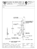
D. PRESSURE RELIEF VALVE
A pressure relief valve is installed into the right front side of the manifold. It is required that it meets
the requirements of ANSI/ASME Boiler and Pressure Vessel Code, Section IV or CSA B51: Boiler
Pressure Vessel and Piping Code as applicable for heating boilers. A ¾” pipe connected to the pressure
relief valve must be directed to a floor drain or suitable location within 6” of a drain or floor. To protect
the valve from freezing, do not plug or cap the pressure relief valve.
PART 2. ELECTRICAL
A. ELECTRICAL CONNECTION
The electrical connection for the Munchkin is on the left hand side of the unit. There is a ½” knockout
location for an electrical connection for both the incoming power and the circulator connection. All
electrical wiring must be performed by a qualified licensed electrician in accordance with National
Electrical Code ANSI/NEPA to and/or the Canadian Electrical Code, Part 1 CSA C22.1, or to the
applicable codes and standards. For your convenience, we have labeled all the wires that need to be
connected to operate the Munchkin.
The electrical requirements are for standard 120 volts, 60 Hz 15 Amp service. This unit is wired with
#18 awg and fused for no more than 15 Amps.
There are two ground points in the electrical compartment that must be connected to the building
ground system. Connect the building ground to the green ground screw and the green ground wire
inside electrical box provided.
The Incoming power supply
is connected to the Black (Hot) and the White (Neutral).The Munchkin
Control board is polarity sensitive. If the polarity is reversed, the Munchkin control will not sense a
flame and lock out the system.
GENERAL INFORMATION
n
NOTICE
Condensation removal: This is a condensing, high efficiency appliance, therefore
condensation removal must be addressed to avoid damage to surrounding area or
appliance. See Part (4) for Condensate Requirements.
n
DANGER
Serious explosion causing property damage and/or loss of life could result. Under no
circumstances should the relief valve be eliminated, capped or plugged.
n
DANGER
IT IS VERY IMPORTANT THAT THE BUILDING GROUND IS INSPECTED BY A
QUALIFIED ELECTRICIAN PRIOR TO MAKING THIS CONNECTION!
n
DANGER
IT IS EXTREMELY IMPORTANT THAT THIS UNIT BE PROPERLY GROUNDED!

10
ELECTRICAL
It is important that the electrical power is not turned on at this time. Double check all connections and then
turn the power on. The display that is provided with the Munchkin should now be reading the outlet
temperature. Note: see Part 6/Startup Procedure section in the manual to change the temperature setting
or run the heater.
PART 3. GAS CONNECTION
A. GAS CONNECTION
The gas supply shall have a maximum inlet pressure of less than 14” water column (350 mm), ½ pound
pressure (3.5 kPa), and a minimum of 3.5” water column. The entire piping system, gas meter and
regulator must be sized properly to prevent pressure drop greater than 0.5” as stated in the National
Fuel Gas Code. This information is listed on the rating plate. It is very important that you are
connected to the type of gas as noted on the rating plate. “LP” for liquefied petroleum, propane gas
or, “Nat” natural or city gas. All gas connections must be approved by the local gas supplier, or utility
in addition to the governing authority, prior to turning the gas supply on. The nipple provided for the
399VWH is 1
1
/
4” with a mandatory 1 x 1
1
/
4 reducing coupling (provided). Threaded into the branch of
a 1
1
/4” tee and a drip leg fabricated as per the national fuel gas code. The 199VWH has a
3
/4” gas supply
nipple with a
1
/2 x
3
/4 reducing coupling (provided) which is to be threaded into the branch of a
3
/4” tee.
You must ensure that the entire gas line to the connection at the Munchkin is no smaller than 1
1
/
4”
for the 399VWH and
3
/4” for the 199VWH. Once all the inspections have been performed, the piping
must be leak tested. If the leak test requirement is a higher test pressure than the maximum inlet
pressure, you must isolate the Munchkin from the gas line. In order to do this, you must shut the gas
off using factory and field-installed gas cocks (following the lighting instructions in Part 6 Section B.)
This will prevent high pressure. Failure to do so may damage the gas valve. In the event the gas valve
is exposed to a pressure greater than
1
/2 PSI, 14” water column, the gas valve must be replaced. Never
use an open flame (match, lighter, etc.) to check gas connections.
*NOTE: The tank sensor is used only on single Munchkin, single tank applications. For multiple
applications, a mechanical control must be used.
n
WARNING
Failure to follow all precautions could result in fire, explosion or death!

11
GAS CONNECTION
B. GAS PIPING
1. Run the gas supply line in accordance with all applicable codes.
2. Locate and install manual shutoff valves in accordance with state and local requirements.
C. GAS TABLE
Refer to Table (1) to size the supply piping to minimize pressure drop between meter or regulator
and unit.
Maximum Capacity of Pipe in Cubic Feet of Gas per Hour for Gas Pressures of 0.5 psi or Less and a
Pressure Drop of 0.3 Inch water Column
(TABLE 1) (Based on a 0.60 Specific Gravity Gas)
It is recommended that a soapy solution be used to detect leaks. Bubbles will appear on the pipe to
indicate a leak is present. The gas piping must be sized for the proper flow and length of pipe, to
avoid pressure drop. Both the gas meter and the gas regulator must be properly sized for the total
gas load. If you experience a pressure drop greater than 1" WC, the meter, regulator or gas line is
undersized or in need of service. You can attach a manometer to the incoming gas drip leg, by
removing the cap and installing the manometer. The gas pressure must remain between 3.5" and 14"
during stand-by (static) mode and while in operating (dynamic) mode. If an in-line regulator is used,
it must be a minimum of 10 feet from the Munchkin. It is very important that the gas line is prop-
erly purged by the gas supplier or utility. Failure to properly purge the lines or improper line siz-
ing, will result in ignition failure. This problem is especially noticeable in NEW LP installations and
also in empty tank situations. This can also occur when a utility company shuts off service to an area
to provide maintenance to their lines. This gas valve must not be replaced with a conventional gas
valve under any circumstances. As an additional safety feature, this gas valve has a flanged con-
nection to the Venturi and blower.
Nominal
Iron Pipe Internal Length of Pipe (Feet)
Size Diameter
(inches) (inches) 10 20 30 40 50 60 70 80 90 100 125 150 175 200.
3/4 .824 278 190 152 130 115 105 96 90 84 79 72 64 59 55} BTU'S
1 1.049 520 350 285 245 215 195 180 170 160 150 130 120 110 100} PER
1 1/4 1.380 1,050 730 590 500 440 400 370 350 320 305 275 250 225 210} HOUR
1 1/2 1.610 1,600 1,100 890 760 670 610 560 530 490 460 410 380 350 320} X 1,000
n
WARNING
Failure to follow all precautions could result in fire, explosion or death!
D. GAS VALVE CONVERSION
Gas conversion kits may be ordered through your local Heat Transfer Products Inc. Distributor.
n
DANGER
ONLY AN HTP, U.L. APPROVED GAS VALVE CONVERSION KIT SHOULD BE USED TO DO A GAS
CONVERSION ON THIS UNIT. UNDER NO CIRCUMSTANCES SHOULD ANYONE OTHER THAN A
LICENCED CONTRACTOR PERFORM THIS GAS VALVE CONVERSION.
FAILURE TO HEED THIS PRECAUTION WILL RESULT IN SERIOUS INJURY OR DEATH!

2. Cellular foam core piping may be used on air
inlet piping only. Never use cellular foam core
material for exhaust piping.
C. EXHAUST/VENT / AIR INTAKE PIPE
LOCATION
1. Determine exhaust vent location:
a. The vent piping for this boiler is approved for
zero clearance to combustible construction.
b. See Figure 4.1 for an illustration of clear-
ances for location of exit terminals of direct-
vent venting systems.
c. This boiler vent system shall terminate at
least 3 feet (0.9 m) above any forced air
intake located within 10 ft (3 m). Note: this
does not apply to the combustion air intake
of a direct-vent appliance.
d. Provide a minimum of 1 foot distance from
any door, operable window, or gravity intake
into any building.
e. Provide a minimum of 1 foot clearance from
the bottom of the exit terminal above the
expected snow accumulation level. Snow
removal may be necessary to maintain
clearance.
f. Provide 4 feet horizontal clearance from
electrical meters, gas meters, gas regulators,
and relief equipment. In no case shall the
exit terminal be above or below the afore-
mentioned equipment unless the 4 foot hor-
izontal distance is maintained.
g. Do not locate the exit terminal over public
A. GENERAL
1. Install the boiler venting system in accor-
dance with these instructions and with the
National Fuel Gas Code, ANSI Z223.1/NFPA
54, CAN/CGA B149, and/or applicable provi-
sions of local building codes.
2. This boiler is a direct vent appliance and is
listed as a Category IV appliance with
Underwriters Laboratories, Inc. VENT AND
INTAKE AIR PIPE
B. APPROVED MATERIALS FOR EXHAUST
VENT AND INTAKE AIR PIPE
1. Use only Non Foam Core venting material.
The following materials are approved for use
as vent pipe for this boiler:
12
VENTING
n
WARNING
Follow these venting instructions carefully. Failure
to do so may result in severe personal injury, death,
or substantial property damage.
n
WARNING
Do not use Foam Core Pipe in any portion of the
exhaust piping from this boiler. Use of Foam Core
Pipe may result in severe personal injury, death, or
substantial property damage.
NOTICE
Use materials approved by the authority having
jurisdiction. In the absence of other authority, PVC
and CPVC pipe must comply with ASTM.
When installing a condensate pump, select one
approved for use with condensing boilers and
furnaces. The pump should have an overflow switch
to prevent property damage from condensate
spillage.
Condensate from the Munchkin VWH Boiler will be
slightly acidic (typically with a pH from 3.2 to 4.5).
Install a neutralizing filter if required by local codes.
APPROVED VENTING MATERIAL
Item Material
Standards for Installation in:
United States Canada
Vent or
air pipe
and
fittings
PVC schedule
40/80
ANSI/ASTM D1785
CPVC and PVC venting
must be ULC-S636
Certified. IPEX is an
approved manufacturer
in Canada supplying
vent material listed to
ULC-S636
PVC-DWV ANSI/ASTM D2665
CPVC schedule
40/80
ANSI/ASTM F441
Pipe
cement/
primer
PVC ANSI/ASTM D2564
IPEX System 636
Cements & Primers
CPVC ANSI/ASTM F493
n
WARNING
This vent system will operate with a positive
pressure in the pipe. Do not connect vent
connectors serving appliances vented by natural
draft into any portion of mechanical draft systems
operating under positive pressure.
PART 4. VENTING

VENTING
13
walkways where condensate could drip
and/or freeze and create a nuisance or hazard.
h. When adjacent to a public walkway, locate
exit terminal at least 7 feet above grade.
i. Do not locate the exit termination directly
under roof overhangs to prevent icicles
from forming.
j. Provide 3 feet clearance from the inside cor-
ner of adjacent walls.
2. Determine air intake pipe location.
a. Provide 1 foot clearance from the bottom of
the air inlet pipe and the level of maximum
snow accumulation. Snow removal may be
necessary to maintain clearances.
b. Do not locate air intake pipe in a parking area
where machinery may damage the pipe.
c. When venting with a two pipe system, max-
imum distance between air intake and
exhaust vent is 6 feet (1.8 m). Minimum dis-
tance between exhaust vent and air intake
on single boiler is 8” (0.2 m) center-to-cen-
ter. Minimum distance between vents and
intakes on multiple boilers is 8” (0.2 m) cen-
ter-to-center. See Figure 4.2.

14
VENTING
Location of exit terminals of mechanical draft and direct-vent venting systems.
(Reference: National Fuel Gas Code ANSI Z223.1/NFPA 54 2002).
Fig. 4-2 Multiple Vent Spacing*
*Note: Exhaust must extend out 1 foot. There should be no more than 2 vents and 2 intakes then a space of 36” to the
next set of vents.
*Note: There must be a minimum of 36” spacing between every 2 kit grouping.
Fig. 4-3 Multiple Stainless Steel Horizontal Vent Kit Installation – Front View
Fig. 4-1

15
VENTING
D. EXHAUST VENT AND INTAKE AIR PIPE
SIZING
1. For the 399VWH the exhaust vent and air
intake pipes should be 4" and 3" for the
199VWH.
2. The total combined equivalent length of
exhaust vent and intake air pipe should not
exceed 85 feet.
a. The equivalent length of elbows, tees, and
other fittings are listed in the Friction Loss
Table 4.1.
b. For example: If the exhaust vent has two 90°
elbows and 10 feet of PVC pipe we will cal-
culate:
Exhaust Vent Pipe Equivalent Length = (2x5)+10=20 feet
Further, if the intake air pipe has two 90°
elbows, one 45° elbow and 10 feet of PVC
pipe, the following calculation applies:
Air Intake Pipe Equivalent Length = (2x5)+3+10=23 feet
Finally, if a concentric vent kit is used we find:
Total Combined Equivalent Length = 20+23+3=46 feet
Therefore, the total combined equivalent
length is 46 feet which is well below the
maximum of 85 feet.
c. The intake air pipe and the exhaust vent are
intended to penetrate the same wall or roof
of the building.
d. Effort should be made to keep a minimum
difference in equivalent length between the
air intake pipe and the exhaust vent.
4. The minimum combined equivalent length is
16 equivalent feet.
5. The maximum combined equivalent length
can be extended by increasing the diameter
of the vent pipe. However, the transitions
should begin a minimum of 15 equivalent feet
from the boiler.
a. Transitions should always be made in verti-
cal sections of pipe to prevent the conden-
sate from pooling in the vent pipe.
b. Use a 6” x 4” reducing coupling to transition
from the 399VWH boiler connections to 6”
vent.
c. The maximum equivalent length for the
increased diameter vent pipes is 125 feet.
d. If the transition occurs at a distance greater
than 15 equivalent feet from the boiler, the
maximum equivalent length will be reduced.
See Table 4.2. Standard Vent Pipe is 4" and
Oversized Vent Pipe is 6" for the 399VWH.
E. EXHAUST VENT AND AIR INTAKE PIPE
INSTALLATION
1. On the 399VWH Boiler the 4" exhaust vent
connection is located at the rear of the boiler
and the air intake is higher and toward the left
side when the boiler is viewed from the front.
The air intake connection is intended for a slip
fit. No sealant or adhesive is required.
2. See Approved Venting Materials, page 11.
3. Horizontal lengths of exhaust vent must slope
back towards the boiler not less than ¼" per
foot to allow condensate to drain from the
vent pipe. If the vent pipe must be piped
around an obstacle that causes a low point in
the pipe, a drain pipe must be connected to
allow condensate to drain.
4. All piping must be fully supported. Use pipe
hangers at a minimum of 4 foot intervals to
prevent sagging of the pipe where conden-
sate may form.
5. Do not use the boiler to support any piping.
6. A screened straight coupling is provided with
the boiler for use as an outside exhaust termi-
nation.
FRICTION LOSS EQUIVALENT IN PIPING AND FITTINGS
FITTINGS OR PIPING EQUIVALENT FEET
3" 4" 6"
90 DEGREE ELBOW 5' 3' 1'
45 DEGREE ELBOW 3' 1' 1'
COUPLING 0' 0' 0'
AIR INLET TEE 0' 0' 0'
STRAIGHT PIPE 1' 1' 0.5'
V1000 4" VENT KIT 1' 1' N/A
V2000 4" VENT KIT N/A 1' 1'
CONCENTRIC VENT KIT 3' N/A N/A
Transition
Point
(ft from
boiler)
TEL of
Standard
3" Vent
Pipe (ft)
TEL of
Oversized 3"
or 4" Vent
Pipe (ft)
Maximum
TEL of all
Vent Pipe (ft)
15 30 95 125
20 40 77-1/2 117-1/2
25 50 60-1/2 110-1/2
30 60 43 103
35 70 26 96
40 80 8-1/2 88-1/2
None 85 0 85
Table 4.1
Table 4.2: Vent Termination Kits
TEL = Total Equivalent Length
n
WARNING
All joints of positive pressure vent systems must be
sealed completely to prevent leakage of flue
products into the living space.
*Friction loss for long elbow is 1 foot less.

16
VENTING
F. HEATER REMOVAL FROM A COMMON VENT SYSTEM
At the time of removal of an existing heater, the following steps shall be followed with each appli-
ance remaining connected to the common venting system placed in operation, while the other appli-
ances remaining connected to common venting system are not operating.
1. Seal any unused openings in the common venting system.
2. Visually inspect the venting system for proper size and horizontal pitch to determine if there
is blockage, leakage, corrosion or other deficiencies that could cause an unsafe condition.
3. If practical, close all building doors, windows and all doors between the space in which the
appliance remains connected to the common venting system located and other spaces in the
building. Turn on clothes dryers and any appliances not connected to the common venting
system. Turn on any exhaust fans, such as range hoods and bathroom exhausts, at maximum
speed. Do not operate a summer exhaust fan. Close all fireplace dampers.
4. Place in operation the appliance being inspected. Follow the lighting instructions. Adjust the
thermostat so the appliance will operate continuously.
5. Test for spillage at the draft hood relief opening after 5 minutes of main burner operation. Use
the flame of a match or candle or smoke from a cigarette.
6. After it has been determined that each appliance remaining connected to common venting
system properly vents when tested as outlined, return doors, windows, exhaust fans, fire-
place dampers and any other gas burning appliance to their previous condition of use.
7. Any improper operation of the common venting system should be corrected so the installa-
tion conforms with the National Fuel Gas Code, ANSI Z223.1. When resizing any portion of
the common venting system, the common venting system should be resized to approach the
minimum size as determined using the appropriate tables in Appendix G in the National Fuel
Gas Code , ANSI Z 223.1
G. CONDENSATE REMOVAL
This is a condensing high efficiency appliance, therefore this unit has a condensate removal system.
Condensate is nothing more than water vapor, derived from the combustion products, similar to an
automobile when it is initially started. It is very important that the condensate line is sloped away
from and down to a suitable inside drain, if the condensate outlet on the Munchkin is lower than the
drain, you must use a condensate removal pump (kit available from Heat Transfer Products, Inc.) A
condensate filter, if required by local authorities, can be made up of lime crystals, marble or phos-
phate chips will neutralize the condensate. This can be done in the field by the installer or you may
purchase one from Heat Transfer Products, Inc. It is also very important that the condensate line is
not exposed to freezing temperatures, or any other type of blockage. Plastic tubing should be the
only material used for the condensate line. Steel, brass, copper or others will be subject to corrosion
or deterioration. A second vent may be necessary to prevent condensate line vacuum lock if a long
horizontal run is used. An increase to 1” tubing may be necessary.
6 A screened inlet air tee is provided with the
boiler to be used as an outside intake termi-
nation.
7. The following is an optional intake air/exhaust
vent termination available from Heat Transfer
Products, Inc. for the 399M: 4” Stainless Steel
Vent Termination Kit – V2000.
n
DANGER
The Munchkin is not intended to be common vented with any other
existing appliance!

17
VENTING
DIAGRAMS FOR SIDEWALL VENTING
10'-0" MIN.
WHICHEVER IS GREATER
12" OVER MAXIMUM
SNOW LEVEL OR 24"
AND COUPLING (EXHAUST)
EXTERIOR WALLRIGHT SIDE VIEW
ROOF VENT WITH TEE (INTAKE)
EXHAUST
VENT
AND VERTICAL PIPING
ALL HORIZONTAL
COUPLING
TEE
STRAIGHT
SUPPORT BRACKETS
MUST BE USED ON
INTAKE AIR
VENT
24" MIN.
RIGHT SIDE VIEW EXTERIOR WALL
AND VERTICAL PIPING
ALL HORIZONTAL
COUPLING
TEE
INTAKE AIR
VENT
TOP VIEW
STRAIGHT
SUPPORT BRACKETS
MUST BE USED ON
EXHAUST
VENT
EXTERIOR WALL
12" MIN.
1" MIN.
TEE
STRAIGHT
VENT
SIDEWALL VENTING WITH TEE (INTAKE)
AND COUPLING (EXHAUST)
COUPLING
EXHAUST
INTAKE AIR
VENT

18
VENTING
WHICHER IS GREATER
12" OVER MAXIMUM
SNOW LEVEL OR 24"
10'-0" MIN.
RIGHT SIDE VIEW
EXTERIOR WALL
INTAKE AIR
VENT
ROOF VENT WITH
CONCENTRIC VENT KIT
AND VERTICAL PIPING
ALL HORIZONTAL
SUPPORT BRACKETS
MUST BE USED ON
EXHAUST
VENT
EXTERIOR WALL
INTAKE AIR
VENT
SIDEWALL VENTING WITH KIT
RIGHT SIDE VIEW
AND VERTICAL PIPING
VENT KIT
ALL HORIZONTAL
SUPPORT BRACKETS
MUST BE USED ON
EXHAUST
VENT
SIDEWALL VENTING WITH
CONCENTRIC VENT KIT
AND VERTICAL PIPING
ALL HORIZONTAL
EXTERIOR WALL
VENT
EXHAUST
RIGHT SIDE VIEW
MUST BE FACING UP
NOTE: INTAKE LEG
SUPPORT BRACKETS
MUST BE USED ON
INTAKE AIR
VENT
1" MIN.
DIAGRAMS FOR SIDEWALL VENTING

19
PIPING
PART 5. PIPING THE MUNCHKIN VWH TO THE STORAGE TANK
The Munchkin is designed to be connected to a storage tank to supply domestic hot water. Heat
Transfer Products has available storage tanks that are 80/119 gallon size storage tanks constructed in
either Stainless Steel or Glass lined construction. These storage tanks will be directly connected to the
Munchkin VWH supply and return connection. Connect the cold water supply to both the storage
bottom port and the supply side of the Munchkin VWH (shown in Piping details, this section) It is
important that you install a flow check on the supply line of Munchkin VWH before you connect feed
line to the storage. This will allow the cold feed to flow through the storage tank first and not the
Munchkin VWH. It is recommended that you install shut off valves on the cold feed line for ease of
future service. If there is a back flow preventer, or any type of no return valve in the system, then you
must install an additional tee for a suitable potable hot water expansion tank. Connect the Storage tank
return line to the return connection located on the Munchkin VWH (shown in Piping details, this
section). Then connect your hot water outlet located on the storage tank to your hot water plumbing
lines.
A. EXPANSION TANK
A potable hot water expansion tank my be required to offset the water expansion as the water is
heated. In most city plumbing systems, the water meter has a no return or back flow device built into
the system to prevent a back flow of water back into city mains. Some states require back flow pre-
venters on all incoming water supplies. Under these circumstances, you will need a hot water expan-
sion tank listed for potable water use. The expansion tank should be located on the cold inlet piping
close to the water heater. It is important that you follow the expansion tank manufacturer’s installa-
tion guidelines when installing any expansion tank.
See the piping illustrations included in this section, Figs. 5-2 to 5-9 for suggested guidelines in
piping the Munchkin heater with either zone valves or circulator pumps.
*Please note that these illustrations are meant to show system piping concept only, the installer
is responsible for all equipment and detailing required by local codes.
B. HIGH VELOCITY CIRCULATOR PUMP
Every Munchkin VWH is shipped with a high velocity circulating pump to assure the correct amount
of continuous flow through the all stainless steel heat exchanger at all times. If a replacement of the
high velocity circulator pump is needed, it must match the performance of the pump provided with
the Munchkin VWH package. NOTE: The circulator must be designed for potable water systems.
n
WARNING
Plumbing of this product should only be done by a qualified, licensed plumber in
accordance with all local plumbing codes.
n
WARNING
NEVER USE DIELECTRIC UNIONS OR GALVANIZED STEEL FITTINGS WHEN
CONNECTING TO A STAINLESS STEEL STORAGE TANK.
n
WARNING
When raising tank temperature, you increase the risk of scalding – Please use a water
tempering or mixing valve and extreme caution. Consult codes for conformance.

20
Circulator Sizing Chart
BOILER TACO P/N GRUNDFOS P/N Bell & Gossett
199M 1400-20B 26-96 PL-36
399M 1400-50B UPS 32-160 PL-55
PIPING
0
2
4
6
8
10
12
14
16
18
20
22
24
5 10152025303537.540
Flow in Gallons per Minute
Friction in Feet of Head
MUNCHKIN 399VWH MUNCHKIN 199 VWH
C. CIRCULATOR SIZING
The Munchkin VWH Heat Exchanger has a pressure drop which must be considered in your system
design. Refer to the graph below for pressure drop through the Munchkin VWH Heat Exchanger.
*The recommended circulators are based on 1 gpm per 10,000 BTU/hr w/20
/