Page is loading ...

INSTALLATION INSTRUCTIONS
for the
Biltmore Chair
SECTION I - REQUIREMENTS
1. PHYSICAL REQUIREMENTS ................................................................................... 1
2. ELECTRICAL REQUIREMENTS ............................................................................. 1
SECTION II - INSTALLATION
1. UNPACKING THE CARTONS................................................................................... 2
2. UNPACKING THE CHAIR ......................................................................................... 2
3. INSTALLING THE CHAIR BACK .............................................................................. 3
4. REMOVING CHAIR FROM PALLET......................................................................... 4
5. INSTALLATION OF PLATFORM COVERS ............................................................... 4
6. INSTALLATION OF STANDARD MAGNETIC HEADREST AND CUSHION ............ 5
7. INSTALLATION OF CHAIR SEAT UPHOLSTERY .................................................... 6
8. INSTALLATION OF CHAIR BACK UPHOLSTERY ................................................... 6
9. INSTALLATION OF ARMREST ................................................................................. 7
10. INSTALLATION OF OPTIONAL EQUIPMENT .......................................................... 7
SECTION III - OPERATIONAL CHECKS
1. ROTATION LOCK RELEASE ...................................................................................... 8
2. FOOT CONTROL OPERATION .................................................................................. 8
SECTION IV - FINAL CHECK LIST
FINAL CHECK LIST........................................................................................................ 9
003-1228-00 Rev. )
Go To Operation Section
Style F*

Return To Table Of Contents

Biltmore Chair Installation Instructions - 1
INSTALLATION INSTRUCTIONS
for the
Biltmore Chair
SECTION I - REQUIREMENTS
1. PHYSICAL REQUIREMENTS
Before installing the chair ensure that the physical
requirements are met (See Figure 1). The chair
should be at least 18 inches from the nearest wall,
cabinet, or any permanent fixture when in the fully
reclined position. Note that the chair seat moves
forward 4-1/2 inches as the base is raised.
2. ELECTRICAL REQUIREMENTS
Before connecting the line cord to an appropriate
receptacle, make certain that the circuit is protected
by a 15-amp circuit breaker for 120-VAC models,
or a 7.5-amp breaker for 240-VAC models. Ensure
that all wiring is grounded and all electrical codes
are observed.
WARNING - Potential shock hazard
with possible personal injury. To
reduce shock hazard, observe all
electrical codes.
Figure 1
TM
Return To Table Of Contents

2 - Biltmore Chair Installation Instructions
SECTION II - INSTALLATION
1. UNPACKING THE CARTONS
The chair is shipped in two cartons, one large carton
and a smaller carton, containing the following items:
LARGE CARTON
l Chair mounted on a pallet with backrest
disconnected
l Plastic bag containing 3 platform covers and
installation hardware
l Installation instructions (this manual) and
operator’s manual
l Foot Control
SMALL CARTON
l Seat Cushion
l Back Cushion
l A Set of Armrests
l Clear Vinyl Toeboard Cover
l Headrest and Cushion
l Hardware Kit
Check for signs of damage to either carton or to
the contents and that all items listed above are
present. If there is any evidence of damage due to
shipping or if any of the items is missing from the
cartons, notify the shipper at once. Be careful not
to discard any small parts or instruction sheets with
the packing material.
2. UNPACKING THE CHAIR
Use the following procedure to disconnect the chair
from the pallet. Leave the chair on the pallet until
the chair back has been installed.
1. Locate the foot controller and remove and
discard the packing material.
2. Locate the two socket head cap screws and
washers that secure the back of the chair to
the pallet brace (see Figure 2). Using a 5/16-
inch allen wrench, remove the two screws and
washers.
3. Locate the two hex screws and two washers
that secure the pallet cleat to the pallet, as
shown in Figure 2. Using an adjustable wrench,
remove the two screws and washers. Remove
and discard pallet brace and cleat.
4. Locate the two nuts at the front of the chair
base (beneath the upright housing cover) that
secure the chair to the pallet. Using an
adjustable wrench, remove the nuts, washers
and bolts (see Figure 3).
5. Remove packaging material from the chair
back and discard.
Figure 2
Return To Table Of Contents

Biltmore Chair Installation Instructions - 3
Figure 4
SECTION II - INSTALLATION (CONT)
3. INSTALLING THE CHAIR BACK
To install the chair back, use the following
procedure:
1. Remove any remaining packing materials,
tape, etc., and discard them. Remove the tag
from the seat frame.
2. Remove the pivot pins from the chair back
clevis ends by loosening the set screw with a
1/8-inch allen wrench.
4. Align the tow bar bearings with the clevis and
insert the pins on both sides as shown in
Figure 4.
5. Tighten the each set screw to hold the pin in
place. The set screw should be aligned with
the groove in the pin.
Figure 3
Return To Table Of Contents

4 - Biltmore Chair Installation Instructions
4. REMOVING CHAIR FROM PALLET
After the preceding steps are completed, the chair
may be removed from the pallet and placed in the
desired position on the floor. Use the following
procedure:
1. Unwrap the foot control and discard the packing
materials.
2. Grasp the chair by the chair back and/or seat
frame and carefully slide the chair from the
pallet onto the floor and into position.
WARNING: Do not attempt to lift the
chair by the motor bars. The motor
shaft will be damaged (See Figure 5).
5. INSTALLATION OF PLATFORM
COVERS
Before installing the platform covers, make sure
the power cord is plugged in to an appropriate
outlet. Be sure the foot control is unwrapped and
ready for use (Refer to Section III, Para. 2). Use
the foot control to raise the chair to its full up
position. Install the platform covers using the
following instructions:
1. Remove the four phillips head screws from the
parts bag for use on platform covers.
2. Position the center platform cover in place as
shown (See Figure 6).
3. Install the left and right platform covers making
sure they trap the center platform cover in place.
Secure each side cover with two phillips head
screws.
WARNING: After the covers are
installed, check the Safety Bail (See
Figure 6) and make sure it moves freely
up and down to operate the base safety
switch. This is important for safe and
proper chair operation.
MOTOR
BARS
Figure 5
SECTION II - INSTALLATION (CONT)
SEAT HINGES
Figure 6
Return To Table Of Contents

Biltmore Chair Installation Instructions - 5
6. INSTALLATION OF STANDARD
MAGNETIC HEADREST AND
CUSHION
1. Remove the headrest from the small carton;
discard any shipping materials.
2. Insert the headrest tang in the slot and
adjustment bracket at the top of the chair back
(See Figure 7). When properly adjusted, the
headrest should move freely up and down, but
should not move on its own.
The adjusting bracket tension is pre-set
at the factory and should not require
adjustment. If the movement of the
headrest is out of adjustment use the
following procedure:
1) Using an open end wrench, loosen the
two locknuts on the side of the
adjustment bracket.
2) Then, loosen or tighten the adjustment
screws to achieve the desired tension
and re-tighten the locknuts (Figure 7).
3. The headrest cushion is held to the headrest
by a magnet and can be positioned as desired
(See Figure 8).
SECTION II - INSTALLATION (CONT)
CAUTION: Handle all upholstery with care. Do not bend the Headrest, Back or Seat Cushions
as this may cause excessive wrinkles or distortion of the upholstery.
NOTE: All Knight Chair upholstery is made from the highest quality materials available and
is designed for maximum patient comfort, easy cleaning and durability. Knight Chair
upholstery will provide years of service when correctly maintained according to the Operator
and Care Manual. Like all fine upholstery some minor wrinkles, waves or changes may occur.
These changes are natural and in no way effect the performance or life of the product.
Figure 7
Figure 8
Return To Table Of Contents

6 - Biltmore Chair Installation Instructions
7. INSTALLATION OF CHAIR SEAT
UPHOLSTERY
The seat is attached to the two hinges on the main
cross member of the seat frame (See Figure 5).
Use the following instructions:
1. Remove the seat from the upholstery box (the
smaller box); be sure to handle the seat with
care. Locate the hardware kit. Discard all
shipping materials.
2. Raise the chair up to its highest position and
recline the chair back to 45 degrees (Refer to
Section III).
3. Insert the four 1/4-20 hex head screws in the
bottom of the seat and hand tighten 2 turns.
4. Turn the two hinges up into a vertical position.
Lower the seat onto the chair with the seat
resting on the hinges (See Figure 9).
5. Rotate the hinges down toward the hex screws
while allowing the screws to slide into the slots
in the hinges (See Figure 10). Tighten the
screws using a screwdriver or 3/8 inch socket.
8. INSTALLATION OF CHAIR BACK
UPHOLSTERY
The seat back is mounted over the four large head
studs in the chair back (see Figure 11). Use the
following instructions after first raising the back to
a convenient height for installing the cushion.
1. Before installing the chair back cushion, turn
the four cushion mounting studs counter
clockwise until they are approximately 5/16
to 3/8 inches from the top of the boss (See
Figure 11).
2. Position the chair back cushion on the chair
back and align the four cushion mounting studs
with the holes in the chair back cushion (See
Figure 11).
3. With the chair back cushion held tight against
the chair back, push downward to lock the
cushion into place.
4. Secure the velcro strips on the cushion skirt to
the velcro strips on the chair back. Smooth the
skirt out with your hand to remove any wrinkles.
SECTION II - INSTALLATION (CONT)
Figure 10
Figure 9
SEAT
SCREWS
SLIDING INTO
HINGE SLOTS
HEX
SCREW IN
SEAT
BOTTOM
HINGE IN
VERTICAL
POSITION
SEAT FRAME
Figure 11
Return To Table Of Contents

Biltmore Chair Installation Instructions - 7
9. INSTALLATION OF ARMREST
The armrests are held in position by a set screw
located in the back of the hip post. A pivot
mechanism allows the armrest to swing out, while
the armrest post remains stationary. Use the
following procedure to install the armrests:
1. Unpack the armrests and discard all packing
materials. The armrests are secured to the
bottom of the small carton (Figure 12).
2. Insert the armrest post in the hip post, making
sure that the right and left hand mounting
positions are observed (See Figures 13 & 14).
3. Position the armrest parallel to the side of the
chair and tighten the set screw (See Figure 13).
NOTE: The set screw must be tighten
with considerable force to keep the
armrest post from turning. The armrest
should pivot only at the pivot
mechanism.
NOTE: We recommend disabling the
swing out feature on the side of the
chair opposite patient access. To lock
the armrest and disable the swing out
feature, remove the pivot screw and
washer on the underside of the armrest
and turn the stop plate 90
0
. Replace the
pivot screw and washer and tighten
(See Figure 14).
10. INSTALLATION OF OPTIONAL
EQUIPMENT
If optional equipment was ordered with the chair, it
should be installed in accordance with the
instructions included in the optional equipment
package.
SECTION II - INSTALLATION (CONT)
Figure 12
Figure 13
Figure 14
Return To Table Of Contents

8 - Biltmore Chair Installation Instructions
SECTION III - OPERATIONAL CHECKS
When the installation is complete, certain
operational checks should be made, as
follows:
1. ROTATION LOCK RELEASE
To ensure that the chair rotates freely, unlock the
manual rotation lock release (Figure 15). Press the
left-hand knob to release the lock. Check that the
chair rotates freely, and then lock the chair by
depressing the right-hand side of the lock release.
The chair will rotate a total of 90
0
(45
0
on either
side of the center line).
2. FOOT CONTROL OPERATION
The foot control (See Figure 16), consisting of a
selector (toggle) switch and a control disk, is
operated as follows:
l The Selector Switch toggles to the Operate
(green) or Automatic Exit (yellow) positions
l The Operate position is actuated by pressing
the selector switch to the position indicated in
green. At this position the control disk is
functional and the chair can be positioned as
follows:
1. Actuate and hold the control disk to the
desired quadrant (See Figure 16). For
example, sliding the disk to the left will
actuate the back-down position.
2. Two functions can be actuated
simultaneously by sliding the disk in a
diagonal direction. For example, Figure 17
illustrates the simultaneous actuation of the
back-down and base-up functions.
3. Releasing the disk stops the movement of
the chair.
l The Automatic Exit position is actuated by
pressing the selector switch to the position
indicated in yellow. At this position the control
disk is nonfunctional.
WARNING: Once the Automatic Exit
function is actuated, this function may
be stopped by pressing the selector
switch to the operate position.
Figure 15
Figure 17
ILLUSTRATION
OF DISK
FUNCTIONS
CONTROL
DISK
SELECTOR
(TOGGLE)
SWITCH
Figure 16
YELLOW/
AUTOMATIC
EXIT POSITION
GREEN/
OPERATE POSITION
Return To Table Of Contents

Biltmore Chair Installation Instructions - 9
SECTION IV - FINAL CHECK LIST
When all the assembly and installation procedures are completed, the chair should be
checked out in accordance with the following check list to ensure that assembly is
complete and that all controls function properly.
Check all controls for proper operation.
Check operation of safety bail.
Check chair rotation, stops and locking functions.
Check the armrests to ensure proper functioning
and that the armrest post is secured an will not
move.
Be sure that the cushions are properly installed
and the toeboard cover is in place.
Check that the platform covers are installed.
Be sure that all optional equipment has been
installed.
Check that all shipping tape and other packaging
materials have been removed and disposed of.
Make sure that the chair has been cleaned and
that all dirt and finger prints have been removed.
Be sure the person who will operate the chair
receives the operators manual and any other
appropriate information or instructions.
240 Volt Chair Only
120 Volt Chair Only
US
42185
Return To Table Of Contents

10 - Biltmore Chair Installation Instructions
NOTES:
Return To Table Of Contents

Operation and Care Manual
The Biltmore Chair
Model P
CONTENTS
Introduction ......................................................... 1
Label Definitions .................................................. 1
Controls and Components ................................ 2
Requirements ...................................................... 3
Operation ............................................................ 4
Cleaning and Maintenance.............................. 6
Warranty............................................................... 7
Return To Installation Section

This publication is a user's manual containing all the information you will need to operate and
care for your Biltmore Chair. Before operating your chair, please read this manual to become
familiar with its special features and functions.
The Biltmore Dental Chair provides exceptional comfort and support during dental procedures.
The chair is fully adjustable, from upright to beyond horizontal, to ensure maximum patient
comfort and ready access to the patient by the operator.
Designed for reliability and simplicity of function, your chair will provide you with years of
service with a minimal amount of maintenance.
“DANGER - EXPLOSION HAZARD - DO NOT
USE THIS EQUIPMENT IN THE PRESENCE OF
FLAMMABLE ANESTHETICS”
Hazards which result in severe
personal injury or death.
Hazards which could result in
personal injury.
Hazards which could result in
equipment or property damage.
Alert user to pertinent facts and
conditions.
CONFORMSTO
UL STD. 544
CERTIFIED TO
CAN/ CSA - C22.2
NO.125-M1984
®
C
®
Label Definitions
Introduction
Return To Table Of Contents

PAGE 1
Introduction
Authorized EU Representative
Countries in the EEC should direct all questions, incidents, and
complaints to Midmark’s Authorized CE representative listed below:
Midmark EMEA Ltd
Beech House
First Floor, East Wing
Ancells Business Park
Fleet
Hampshire
United Kingdom
Tel: + 44 (0) 1252 360 940
Fax: + 44 (0) 1252 360 941
Return To Table Of Contents

Controls and Components
PAGE 2
MAGNETIC HEADREST -
provides comfortable support
for the patient’s head and
neck throughout the dental
procedure.
BACKREST AND LUMBAR
SUPPORT - a contoured
seamless seat and lumbar
cushion support for the
patient’s back.
BUCKET SEAT - The seamless
seat is contoured to ensure
patient comfort throughout the
dental procedure.
SWING-OUT ARMRESTS -
provide easy access to or from
the chair on either side.
VINYL TOEBOARD COVER - fits
over the end of the bucket
seat to protect the upholstery.
MANUAL ROTATION LOCK
RELEASE - Located at the lower
right side of the chair (can be
relocated for left hand set up),
this lever allows the operator to
The components and controls identified are described below. Read the
descriptions carefully to familiarize yourself with these components
rotate the chair base up to 90
O
and lock it in place at the
desired position.
FOOT CONTROL - controls the
proper positioning of the chair.
It also provides two automatic
positions - auto exit and
programmable operation.
AVAILABLE ON EC MODELS
Return To Table Of Contents

PAGE 3
This equipment is rated
Class I, Type B
WARNING - Potential
shock hazard with
possible personal
injury. To reduce
shock hazard, observe all
electrical codes.
WARNING - To
disconnect power to
the chair, you must
unplug the power
cord from the electrical outlet.
PHYSICAL REQUIREMENTS
The illustration below shows
the basic space requirements
of your Biltmore Chair. The
chair should be at least 18
inches from the nearest wall,
cabinet, or any permanent
fixture when in the fully
reclined position. Note that
the chair seat moves forward
4-1/2 inches as the base is
raised.
ELECTRICAL
REQUIREMENTS:
Before connecting the line
cord to an appropriate
receptacle, make certain that
the circuit is protected by a 15-
amp circuit breaker for 120-
VAC models, or a 7.5-amp
breaker for 240-VAC models.
Ensure that all wiring is
grounded and all electrical
codes are observed.
Requirements
Return To Table Of Contents

The Biltmore Chair is designed for convenient operation. This section will
explain in detail the functions of the electrical and manual controls.
Refer to page 2 for a general description and location of these controls.
Operation
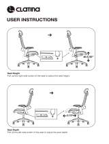
MAGNETIC
HEADREST
CUSHION
HEIGHT
ADJUSTMENT
STANDARD MAGNETIC HEADREST
The headrest height can be easily adjusted by
simply pulling out or pushing in on the headrest
assembly. The cushion is held to the headrest by
a magnet and can be positioned as desired.
ROTATION LOCK RELEASE
The chair will rotate at its base a total of 90
0
(45
0
on either side of the center line) Press the
left hand side of the rotation lock release and
rotate the chair to the desired position. Lock
the chair in place by depressing the right-hand
side of the lock release.
SWING OUT ARMREST
Grasp the armrest and pull out away from the chair. With the
patient seated, push the armrest back until it latches.
We recommend disabling the swing out feature on the side
of the chair opposite patient access. To lock the armrest and
disable the swing out feature, remove the pivot screw and
washer on the underside of the armrest and turn the stop
plate 90
0
. Replace the pivot screw and washer and tighten.
PAGE 4
Return To Table Of Contents

Operation
FOOT CONTROL OPERATION
The foot control consisting of a selector
(toggle) switch and a control disk, is
operated as follows:
l The Selector Switch toggles to the
Operate (green) or Automatic Exit
(yellow) positions
l The Operate position is actuated
by pressing the selector switch to the
position indicated in green. At this
position the control disk is funtional and
the chair can be positioned as follows:
1. Actuate and hold the control
disk to the desired quadrant. For
example, sliding the disk to the left
will actuate the back-down
position.
2. Two functions can be actuated
simultaneously by sliding the disk in
a diagonal direction. For example,
the illustration shows the
simultaneous actuation of the
back-down and base-up functions.
3. Releasing the disk stops the
movement of the chair.
l The Automatic Exit position is
actuated by pressing the selector
switch to the position indicated in
yellow. At this position the control disk is
non-funtional.
WARNING: Once the
Automatic Exit function is
actuated,this function may
be stopped by pressing the
selector switch to the
operate position.
PAGE 5
Return To Table Of Contents

DA177500i
Protective
Barrier
PAGE 6
DA148100i
Read
carefully
Disinfecting Procedures for External Surfaces
Barriers:
Attention!
Midmark assumes no responsibility or liability for any result,
expressed or implied. These are suggested practices, based
on the best information available at this time.
At the beginning of each workday...
Use barrier protection to cover any surfaces
that must be protected from contamination.
Note:
Barriers should always be
changed between patients.
Note
The use of single-use barriers and disposable items
will significantly reduce the frequency and need for
chemical usage, thus prolonging the life of the
equipment. Barrier material must be impervious
(does not allow penetration or passage) to moisture /
fluids.
Some examples:
• Plastic covers available at your
dealer, or equipment manufacturer.
• Clear plastic wrap
• Plastic bags
• Plastic sheets
• Plastic tubing
• Plastic-backed paper
• Similar materials
Chemical Disinfectant:
Organization for Safety & Asepsis Procedures
http://www.osap.org/index.cfm
American Dental Association
http://www.ada.org/prof/resources/topics/icontrol/index.asp
Dept. of Health & Human Resources
Centers for Disease Control & Prevention (CDC)
http://www.cdc.gov/OralHealth/infectioncontrol/index.htm
DA177400i
Read
carefully
Note
Every dental practice setting is different and no one
disinfectant is the best choice for every facility.
Due to this fact there are several organizations, educated
in disinfection procedures, with web sites that can assist
dental personnel in choosing what is best for their
practice.
Listed below are several links to some of those sites.
WARNING
If a surface has been contaminated,
it will need to be cleaned and disinfected
using proper techniques, and EPA-registered
hospital disinfects.
Equipment Alert
No materials available for the manufacture of dental equipment
are impervious to every chemical. Midmark does incorporate
the most chemical-resistant materials available in our dental
line of equipment.
Use of barriers are the most effective means to prevent
equipment damage.
When using a disinfectant:
• Carefully read the product
label and directions for use.
• Do not exceed the dilution rate.
Cleaning and Maintenance
Return To Table Of Contents
/