
FOR OUTDOOR USE ONLY AUSTRALIA / NEW ZEALAND
Assembly and Operating Instructions
INTEGRATED
SIDE BURNER
BSW316SA

2 CONTENTS
General warnings ��������������������������������������������������������������������������3
Product description �����������������������������������������������������������������������4
Gas specifications ��������������������������������������������������������������������������6
Gas connection detail ��������������������������������������������������������������������6
Natural gas installation�����������������������������������������������������������������7
Leak test procedure ����������������������������������������������������������������������7
Universal LPG installation ������������������������������������������������������������8
Gas bottle safety ����������������������������������������������������������������������������9
Installation warnings �������������������������������������������������������������������10
Installation instructions ��������������������������������������������������������������11
Dimensions ����������������������������������������������������������������������������������12
Gas requirements ������������������������������������������������������������������������13
Positioning of burner �������������������������������������������������������������������13
Connecting to the integrated barbecue ��������������������������������������14
Burner operation �������������������������������������������������������������������������15
Pivoting safety leg ������������������������������������������������������������������������15
Cleaning and care ������������������������������������������������������������������������16
Troubleshooting ���������������������������������������������������������������������������17
Accessories ����������������������������������������������������������������������������������17
Notes ��������������������������������������������������������������������������������������������18
Warranty ��������������������������������������������������������������������������������������21
Please read the user manual carefully and store in a handy
place for later reference�
The symbols you will see in this booklet have these
meanings:
WARNING
WARNING
This symbol indicates information concerning your
personal safety.
WARNING
CAUTION
This symbol indicates information on how to avoid
damaging the appliance.
TIPS & INFORMATION
IMPORTANT
This symbol indicates tips and information about use
of the appliance.
ENVIRONMENTAL TIPS
ENVIRONMENT
This symbol indicates tips and information about
economical and ecological use of the appliance.
Dear customer,
Congratulations and thank you for choosing our barbecue�
We are sure you will find it a pleasure to use� Before you use
the barbecue, we recommend that you read through the
relevant sections of this manual, which provide a description
of your appliance and its functions�
To avoid the risks that are always present when you use
an appliance, it is important that the appliance is installed
correctly and that you read the safety instructions carefully to
avoid misuse and hazards�
We recommend that you keep this instruction booklet
for future reference and pass it on to any future owners�
After unpacking the appliance, please check it is not
damaged� If in doubt, do not use the appliance but contact
your local customer care centre�
This appliance complies with requirements of Australian
Standards AS4557�
CONDITIONS OF USE
These important notes apply to your appliance
• This appliance MUST be installed and serviced only
by a qualified licensed person�
• This product is intended for personal, domestic or
household use only, not commercial use�
• This product is intended for outdoor use only�
• This product must be installed, operated and maintained
as per the instructions�
• Ventilation holes in the unit must not be obscured by the
installation�
Please ensure you read the instruction manual fully
before you call for service, or a full service fee could
be applicable.
Record model and serial number here:
Model number: �������������������������������������������������������������������������������
Serial number: ��������������������������������������������������������������������������������
PNC: ������������������������������������������������������������������������������������������������
CONTENTSCONGRATULATIONS

3SAFETY
Please read the user manual carefully and store in a handy
place for later reference�
TIPS & INFORMATION
IMPORTANT
Important – check for any damages or marks
If you find the barbecue is damaged or marked, you must
report it within 7 days if you wish to claim for damage/
marks under the manufacturer’s warranty. This does not
affect your statutory rights.
ENVIRONMENTAL TIPS
ENVIRONMENT
Information on disposal for users
• Most of the packing materials are recyclable. Please
dispose of those materials through your local recycling
depot or by placing them in appropriate collection
containers.
• If you wish to discard this product, please contact
your local authorities and ask for the correct method
of disposal.
WARNING
WARNING
This appliance must be serviced only by a qualified
licensed person.
Improper installation, adjustment, alteration or
maintenance can cause injury or property damage.
Please contact your nearest Electrolux Service
Department for additional information or assistance
for an approved installer.
NOTE: This manual must remain with the owner for future
reference�
WARNING
WARNING
• Do not lean over barbecue when lighting.
• Do not leave the barbecue unattended when alight.
• Do not delay lighting once the gas has been turned on.
• Do not store or use aerosol cans in the vicinity of the
barbecue.
• Do not store flammable liquids in the vicinity of the
barbecue.
• Do not use caustic or abrasive based cleaners on the
barbecue.
• Do not attempt to dismantle or adjust the control
valves.
• Do not attempt to dismantle or adjust the regulator.
• Do not test for leaks with a naked flame.
• Do not modify the construction of this appliance or
modify the injector orifice size.
• Do not obstruct any ventilation of the barbecue.
• Do not allow children to operate or play near the
barbecue.
WARNING
CAUTION
This barbecue is supplied set up for Natural Gas and is
labelled accordingly. A Universal LPG conversion kit is
included if required. Conversion of this unit to Universal
LPG must be carried out by a qualified licensed person and
a Certificate of Compliance must be issued to the owner at
the completion of the installation and conversion.
IMPORTANT SAFETY INSTRUCTIONS

4 PRODUCT DESCRIPTION
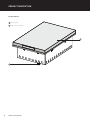
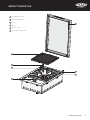
PRODUCT DESCRIPTION
1
Slimline lid
2
Gas connection point
Integrated burner
2
1

5PRODUCT DESCRIPTION
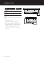
PRODUCT DESCRIPTION
8
3
4
6
4
5
7
3
Pivoting lid safety leg
4
Lid mounting bracket
5
Trivet
6
Burner
7
Burner control
8
Reversible cast grill plate

6
GAS SPECIFICATIONS
GAS SPECIFICATIONS
GAS TYPE
NATURAL
GAS
UNIVERSAL LPG
Maximum gas
consumption
22 MJ/h 23 MJ/h
Injector office
diameter
2�10mm 1�25mm
Number of
injectors
1 1
Regulator
pressure
1�00 kPa 2�75 kPa
78
112
170
NOTES:
• This appliance MUST be installed and serviced only by
a qualified licensed person�
• This product is intended for outdoor use only�
• This product must be installed as per the instructions
which requires the installation of venting to enable
the barbecue to operate correctly� Failure to provide
adequate ventilation for supply of air to the appliance
may result in poor burner performance or excessive
heat build-up within the mounting enclosure�
• Ventilation holes in the unit must not be obscured by
the installation�

7NATURAL GAS INSTALLATION
NATURAL GAS INSTALLATION LEAK TEST PROCEDURE
This barbecue is supplied set up for Natural gas and is
labelled accordingly� A Universal LPG conversion kit is
supplied if required� Refer to Universal LPG installation for
details�
Connecting the appliance to an NG gas supply
Components supplied in a bag for NG are:
• Natural gas regulator
• Natural gas installation pipe
• 2 x fibre washers
Preparing the unit for Natural Gas connection
to mains
Natural gas connection to be made by a licensed gas fitter�
Preparing the unit for Natural Gas installation
Fit natural gas installation pipe to the gas inlet to enable
access to the regulator in the installed position� When
tightening the regulator or any other connection
do not over-tighten�
1� Fitting the natural gas installation pipe�
Fit pipe ensuring the blue fibre washer is in place�
Do not over-tighten�
2� Fitting the regulator�
Fit the regulator ensuring the blue fibre washer is in
place and the arrow indicating the gas flow is correct�
Do not over-tighten�
3� Connect to consumer piping�
- The NG regulator inlet has a 1/2” parallel pipe thread�
- The inlet of the NG regulator may be connected to
consumer piping using a suitable hose assembly if
required�
• Ensure gas valve is in the ‘OFF’ position�
• In a small container, mix a solution of water and detergent or
soap�
• After connection of the hose, turn on the gas supply at the gas
bottle or mains as appropriate�
• Using a brush apply the solution to the gas connection points
and look for bubbles forming�
• Bubbling will indicate a leak�
• Turn off the gas supply and re-tighten the joint� Repeat the
leak test�
• If the leak persists, turn off the gas at the isolation valves and
contact a licensed gas fitter to correct�
Leak test point
Leak test point
Check hose for signs
of abrasion, cracks
or leaks
Gas inlet pipe
Fibre washer
Fibre washer
NG installation pipe
NG regulator
(ensure arrow is in
correct direction)
Consumer piping

8
UNIVERSAL LPG INSTALLATION
UNIVERSAL LPG INSTALLATION
NOTE: Conversion of this unit to Universal LPG must be
carried out by a qualified licensed person and a Certificate
of Compliance must be issued to the owner on completion of
the installation and conversion�
Converting the Unit to Universal LPG
This barbecue is supplied set up for Natural gas and is
labelled accordingly� A Universal LPG conversion Kit is
supplied with the product�
The components required for conversion are:
• Brass adaptor�
• Fibre washer�
• Small plastic bag containing:
• 1 x 1�25mm brass injector
• LPG sticker
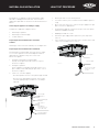
To convert the appliance, proceed as follows:
1� Remove screw and cover panel on base of burner box�
Screw
Cover panel
Burner
Screw
2� Remove two screws fastening burner�
3� Remove burner from burner box�
4� Replace Natural gas injector (2�10mm)
with Universal LPG injector (1�25mm)�
Injector

9
UNIVERSAL LPG INSTALLATION
GAS BOTTLE SAFETY
GAS BOTTLE SAFETY
5� Replace burner and cover panel�
6� Remove Natural Gas sticker on the base panel and
replace with Universal LPG sticker provided�
The final step in the conversion of the barbecue to Universal
LPG is the adjustment of the turndown setting� This can only
be completed after the barbecue has been connected to a
supply of Universal LPG� Connecting to a Portable 9kg LPG
Cylinder or Connecting to remote supply of LPG�
Adjust the turndown setting on the valve�
To complete the conversion to Universal LPG the turndown
setting of the valve will need to be adjusted, and at the same
time the operation of the appliance can be tested� Proceed
as follows:
• Check that the burner ignites (REFER OPERATING
INSTRUCTIONS)�
• Light the burner and rotate the control knob to the
lowest setting, then remove the knob from the valve
shaft, and remove the grommet�
• Using a small flat-blade screwdriver adjust the
turndown adjustment screw to achieve a small steady
flame on the burner�
• Replace the grommet and the knob�
• Recheck the operation of the burner at maximum
and turndown�
Connecting the appliance to an LPG gas supply
The appliance may be supplied LPG from either:
• A 9kg portable LPG cylinder, or
• A remote supply of LPG via fixed pipework�
Turndown adjustment screw
Gas bottle safety information
• This appliance is designed to use a 9kg (20 lbs)
gas cylinder�
• The gas cylinder must be made and marked in
accordance with specifications for LPG or Propane
cylinders�
• It is recommended to turn off the cylinder valve when
the appliance is not in use�
• Gas cylinders must be stored in an approved housing out
of reach of children�
• When disconnecting the gas bottle ensure that all the
control valves are in the ‘OFF’ position�
• Remove the bottle from any housing in which it may
be stored before disconnection�
• When reconnecting the hose to the bottle, ensure
that all connections are tight before replacing in the
storage compartment�
• Carry out a leakage check as detailed below after
each reconnection�
Connecting to a Portable 9kg LPG Cylinder
The components required to make this type of connection
are included�
The components required are:
• LPG hose and regulator assembly to suit 9 kg cylinder
• Brass adapter
• Sealing washer�
To assemble the connection (refer diagram below):
• Connect the brass adapter to the barbecue gas inlet with
the sealing washer in place to seal the connection� Then
assemble the hose to the brass adapter�
• Connect the POL fitting at the inlet of the regulator to
the valve on the LPG cylinder�
• Leak test all connections in the assembly as described
under LEAK TEST PROCEDURE�
Gas inlet pipe
Fibre washer
Brass adaptor
LPG hose and
regulator

10
GAS BOTTLE SAFETY
GAS BOTTLE SAFETY
INSTALLATION WARNINGS
Gas inlet pipe
Fibre washer
Test point adaptor
- ensure arrow is in
the right direction
Supply hose or pipework
with 1/2’ tapered thread
- sealed with thread
seal tape or compound
suitable for gas
connection
Connecting to a remote supply of LPG
The components required to make this type of connection
are available as an accessory and can be purchased either
on the Electrolux spare parts website or by contacting the
Electrolux Customer Service Centre� Refer to Accessories
section on page 17�
Never connect the barbecue to an unregulated LPG supply�
Ensure that the supply pressure at the inlet of the barbecue
is 2�75kPa�
Electrolux strongly recommends installation of a manual
shut-off valve, or hose assembly with a certified quick
connect that is accessible with the appliance installed, so
that the appliance may be isolated from gas in the event of
an emergency or for servicing�
The components required are
• Brass test point adapter
• Sealing washer
To assemble the connection:
• Connect the brass test point adapter to the barbecue
gas inlet with the arrow on the adapter oriented
according to direction of gas flow, with the sealing
washer in place to seal the connection�
• The inlet to the adapter has a standard internal ½”
pipe thread and can connect to any standard external
½” tapered threaded connection� This connection is
sealed with any thread tape or sealing compound that
is suitable for gas connections� Connect the fixed LPG
pipework to the inlet of the test point adapter by any
suitable means in accordance with requirements of
AS 5601�
• Leak test all connections in the assembly as described
under LEAK TEST PROCEDURE�
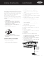
WARNING
WARNING
• This appliance shall only be used in an above ground,
open air situation with natural ventilation, without
stagnant areas, where gas leakage and products of
combustion are rapidly dispersed by wind or natural
convection� This barbecue has been designed for
outdoor use only� Refer to diagrams below�
• Never install this barbecue inside any building,
garage, shed or breezeway or inside a boat, caravan or
recreational vehicle� This is to prevent the possibility of
fire or carbon monoxide poisoning or asphyxiation�
• Any enclosure in which this appliance is installed shall
comply with one of the following:
- An enclosure with walls on all sides, but at least
one permanent opening at the ground level and no
overhead covering�
- Within a partial enclosure that includes an overhead
cover and no more than 2 walls�
-
Within a partial enclosure that includes an overhead
cover and more than 2 walls, the following shall apply:
- At least 25% of the total wall area is completely open
and at least 30% of the remaining wall area is open
and unrestricted�
• In the case of balconies, at least 20% of the total of the
side, back and front wall areas shall be and remain open
and unrestricted�
Outdoor area
example 1
Outdoor area
example 2
Both ends
open
Outdoor area
example 3
Open side at least 25%
of total wall area
30% or more in total of the
remaining wall area is open
and unrestricted
Outdoor area
example 4
Outdoor area
example 5
Open side at least 25%
of total wall area
30% or more in total of the
remaining wall area is open
and unrestricted

11INSTALLATION INSTRUCTIONS
INSTALLATION INSTRUCTIONS
Installation warnings
The mounting enclosure
• The barbecue requires a non-combustible barrier under
the barbecue to prevent excessive temperatures being
accessed� The barrier panel is to be placed at least
30mm under the base of unit�
• The benchtop that supports the barbecue must be
constructed from non-combustible material� Suitable
materials include masonry, granite, marble, Hardiplank
®
,
Villaboard
®
over a metal frame, or tiles on a non-
combustible substrate�
• This appliance requires venting� Refer to diagrams {on
next page} for vent specification and location�
• For ULPG use, cabinetry below the barbecue must
have low level venting to prevent the possibility of
LPG accumulating�
• Ensure there is a minimum of 20mm clearance on all
sides, between the sides of the barbecue and the support
structure�
When planning the location and preparing the installation
structure for this appliance note the following:
• This appliance must be installed in accordance with
Australian Standard AS 5601 and in accordance with
local authority�
• Requirements in these instructions for clearances
to combustible materials also apply to combustible
materials that have non-combustible materials attached
to their surface�
• This appliance must be installed such that no part of
the appliance is in contact with or within 10mm of any
combustible material�
• The minimum clearance to a vertical wall or splashback
above bench level and behind the barbecue that is made
from combustible material is 450mm for a model with a
roasting hood and 200mm for a slimline lid model�
• The vertical clearance above the cooking surface to any
combustible materials must be at least 1000mm�
• The minimum clearance to a vertical wall above bench
level made from combustible material is
• 150mm from the left side of the barbecue, and
• 20mm from the right side�
• When using LPG in an enclosure ventilation must be
provided� Gas is highly explosive and can cause serious
injury and damage to property if allowed to accumulate
and then be ignited�
• This barbecue is intended to be built into a benchtop
with a minimum depth (front to rear) of 600 mm�
• Avoid windy positions as this will affect cooking
performance and burner efficiency� If this situation
cannot be avoided some shielding may be necessary�

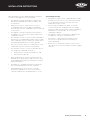
12 INSTALLATION INSTRUCTIONS
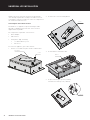
DIMENSIONSINSTALLATION INSTRUCTIONS
Bench width 600mm min�
540mm
136mm 42mm
465mm
71mm min�
From cutout
549mm
WARNING!
• This appliance requires venting� This vent is to allow
air into the enclosure for the correct combustion of
gases and for the correct exhausting of the products of
combustion� The vent must be no less than 250mm x
25mm unless installed adjacent to integrated barbecue
refer to diagram on page 13�
Vent 250mm x 25mm (required
when installed separately to
barbecue)
540mm
540mm
480mm
71mm min
325mm
80mm min
350mm
350mm
Bench width 600mm min�
Side view - lid up
Side view - lid down

13
GAS REQUIREMENTS POSITIONING OF BURNER
Installation warnings
Natural Gas requirements
• The enclosure must be constructed so that access can
be gained to the Natural Gas regulator at all times�
• For pipe sizing requirements for supply pipe refer
to AS5601�
Universal LPG requirements
• If an LPG bottle is to be stored in the enclosure under
the burner unit, it must be isolated from the burner
unit with a non-combustible panel� The enclosure must
comply with the requirements of AS5601�
• AS5601 ventilation requirements for cylinder storage
are:
– Where of sheet metal or similar impervious
construction there shall be ventilation openings
at the top and bottom of the enclosure or recess,
each opening providing a free area of at least 200cm
2
for every cylinder enclosed�
• For ULPG installations having enclosed cabinetry below
the separation panel that does not contain a gas bottle,
low level venting must be installed� This is to allow the
gas which is heavier than air escape from the enclosure
in the situation where there may be a leak� A minimum
opening of 200cm
2
is required�
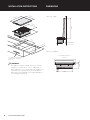
When installing integrated burner with the integrated
barbecue, ventilation to the side burner can be achieved
from one common vent (as shown above)� Provided there is
no restriction of airflow in the enclosure construction (i�e� no
separation panel between barbecue and side burner)�
A minimum clearance of 80mm (as shown on page 12) must
be observed� This prevents heat transfer between units�
Refer to manufacturer’s instructions for construction
requirements of specific bench top materials�
Vent 700mm x 25mm
GAS REQUIREMENTS

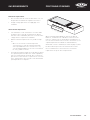
14 CONNECTING TO THE INTEGRATED BARBECUE
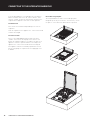
CONNECTING TO THE INTEGRATED BARBECUE
Reversible cast grill plate
The integrated burner features a reversible grill plate
designed specifically to sit onto the cast iron trivet, ensure
the plate is centered over the burner before operation�
If the integrated burner is located adjacent to the built in
barbecue and the units are to be connected to the same
outlet or cylinder, the gas line must branch off prior to the
regulator� Each appliance must have its own regulator�
For Natural Gas
This can be achieved with hard plumbing to each of the
regulators�
From the regulator to the appliance the connection method
remains unchanged�
For Universal LPG
This is achieved by adding fittings to branch off at the
cylinder connection on the high pressure side� To each
branch the regulator and hose assembly is fitted for each
appliance� From the regulator and hose assembly to the
appliance the connection method remains unchanged�
This appliance must be installed by a qualified licensed
person� For piping size requirements for supply pipe refer
to AS5601�

15
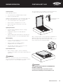
BURNER OPERATION PIVOTING SAFETY LEG
Installation warnings
Control functions
Before lighting the burner:
• Check that all hoses and gas fittings are tight�
• Remove or pivot lid to open�
NOTE: The lid is designed as a cover for weather protection�
The lid is not designed to be used as a cooking hood�
• Check control knob is in the ‘OFF’ position�
• Ensure that the cooking surfaces are clean�
• Ensure that the gas isolation valve or the LPG
bottle are ‘ON’�
Lighting instructions
• Do not attempt to light burner with the cooking
surfaces covered�
• To light burner, depress the knob and rotate
to ‘BOOST’�
• If burner did not light, turn knob to the ‘OFF’ position�
Allow gas to disperse, then repeat lighting procedure�
Manual lighting
• If, in the event of the ignition system not working,
the burner can be lit manually�
• Rotate the knob to the ‘BOOST’ and place
a lighted match near to the burner�
• If the unit does not operate correctly refer to the
troubleshooting section on page 17�
To turn the burner off
• When cooking is complete, rotate the knob fully
clockwise so the pointer on the knob is positioned at the
off position�
WARNING!
Ensure the cast trivet is in the correct orientation with
the 4 feet on the trivet located into the recess in the hob� The
height of the trivet is critical for burner operation�
To ensure that the user remembers to turn off the gas before
closing the lid, a pivoting safety leg has been fitted�
When closing the lid the safety leg will pivot forward and rest
against the trim surface to prevent the lid closing�
After ensuring the gas has been turned off, to fully close the
lid, the leg needs to be rotated backwards�
WARNING!
THE SLIMLINE LID MUST NOT BE CLOSED WHEN THE
BURNER IS OPERATING.
Closing the lid during burner operation can cause
discolouration and damage to the lid and burner unit.
BURNER OPERATION
Pivoting Safety Leg

16 CLEANING AND CARE
CLEANING AND CARE
The Beefeater integrated burner has been constructed from
select grade stainless steel which, if not cared for, may
discolour over time� To keep your appliance looking its best
we recommend that the cooking surfaces are cleaned after
every use�
Cleaning
• Always ensure the appliance is turned off before
cleaning�
• This appliance contains brass and aluminium fittings�
Do not use caustic based cleaners�
• Do not use steam cleaners as this may cause moisture
build up on electrical components�
• Always clean the appliance immediately after any
food spoilage�
WARNING
CAUTION
Do not place cast iron trivet or grill plate in
a dishwasher�
WARNING
Please ensure that your appliance is switched
off and has cooled down before following the
instructions below�
Cleaning of Stainless Steel surfaces
WARNING
CAUTION
Do not use abrasive or caustic cleaners, scourers or metal
scrapers on the stainless steel surfaces as they may
permanently scratch and damage your appliance.
• Wash all stainless steel components, including the
slimline lid and control knob cap with a soft dishcloth
using hot soapy water�
• The interior can be wiped down with a soft cloth in hot
soapy water�
• Ensure that all surfaces are dried with a clean
dry cloth�
WARNING
CAUTION
Take extra care (particularly when cleaning on and around
the control knob) to ensure that water and soapy residue
do not enter the control panel, where the valve is located or
into the burner.
Trivet and reversible grill plate
The trivet can be removed for cleaning� Clean by washing in
warm soapy water� Take care when replacing the trivets as
dropping them may damage the enamelled surfaces�
Burner
The burner ports should be checked for blockages and
cleared as required� The brass top of burner will become
discoloured with use, this is normal�
Maintenance
IMPORTANT
Special note on “tea staining”
Sometimes stainless steel surfaces are affected by a brown
discolouration called tea staining� This usually occurs in
areas which use high heat and can be easily removed using
specialised stainless steel cleaners� For best results, we
recommend that specialised cleaners be used regularly on
all stainless steel components�
Burners
Burners should be checked at least once per year and
cleaned as necessary� Inspect burners to ensure no residues
have been deposited and gas ports are clear�
NOTE: Environmental conditions need to be taken into
account with regards to the maintenance required on your
product� In particular units installed in humid climates
or seaside locations will be more susceptible to surface
corrosion/discolouration over time� In these conditions
Beefeater strongly recommends cleaning and drying your
barbecue after every use and covering it when not in use to
minimise exposure to the elements�

17
TROUBLESHOOTING ACCESSORIES
Installation warnings
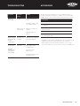
PROBLEM POSSIBLE
CAUSE
REMEDY
Barbecue
won’t light
No gas Check isolation valve
is ON
Gas bottle empty - refill
or change gas bottle
Ignition system
not working
Ignition electrode wet
or dirty
Manually light the
burner
Excess smoke
being emitted
from the
cooking area
Gas valve set
too high
Turn gas valves down or
turn off the burner
Smell of gas
DO NOT
ATTEMPT TO
LIGHT THE
APPLIANCE
Gas leak Turn off gas at the
isolation valves
Check for leaks,
tighten joints
If problem persists call
Electrolux Service
To order any of the following accessories and spare parts, or
for more information on any other suitable accessories for this
product, please contact the Electrolux Customer Service Centre�
ACCESSORIES
standard inclusions+
cast iron reversible grill plate
(as supplied)
gas conversion kit
- Universal LPG
optional extras *
weatherproof cover
(for model BSW316SA)
+ Standard inclusion with the product but can also be purchased
separately via the Electrolux Customer Service Centre�
* Sold separately via the Electrolux Customer Service Centre�
For the full range of accessories please visit beefeaterbbq�com
TROUBLESHOOTING

18 NOTESNOTES
NOTES

19NOTES

20 NOTESNOTES
NOTES
Page is loading ...
Page is loading ...
-
 1
1
-
 2
2
-
 3
3
-
 4
4
-
 5
5
-
 6
6
-
 7
7
-
 8
8
-
 9
9
-
 10
10
-
 11
11
-
 12
12
-
 13
13
-
 14
14
-
 15
15
-
 16
16
-
 17
17
-
 18
18
-
 19
19
-
 20
20
-
 21
21
-
 22
22


Ask a question and I''ll find the answer in the document
Finding information in a document is now easier with AI
Related papers
-
BeefEater BDMG420BA User manual
-
BeefEater BS12840 User manual
-
-
BeefEater BS19340 User manual
-
-
-
BeefEater BB18224 User manual
-
BeefEater BS31560 User manual
-
-
Other documents
-
Electrolux Dishwashers User manual
-
Weber Q 3600 Installation guide
-
Electrolux EQBW40AS User manual
-
-
-
Electrolux EQMW40AS User manual
-
Electrolux EQBM120HAS User manual
-
-
-
COMPANION CS-01 Owner's manual