Page is loading ...

© 2017 Johnson Controls. All rights reserved. All specifications and other information shown were current as of document revision and are
subject to change without notice. Additional listings may be applicable, contact your local Simplex® product supplier for the latest status.
Listings and approvals under Simplex Time Recorder Co. SIMPLEX, and the product names listed in this material are marks and/or registered
marks. Unauthorized use is strictly prohibited. NFPA 72 and National Fire Alarm Code are registered trademarks of the National Fire
Protection Association (NFPA).
579-1203
Rev. B
*05791203B*
R
IMPORTANT. When the notification appliance emits light or sound, it indicates the possibility of an emergency situation that requires immediate attention
of all occupants.
LOCATION REFERENCE. Location and quantity of Appliances required must conform to the applicable local standards and guidelines (the National Fire
Alarm and Signaling Code (NFPA 72); ULC Standard CAN/ULC-S524, Installation of Fire Alarm Systems; the appropriate model building codes, and so on)
and specific requirements of the Local Authority Having Jurisdiction (AHJ). These Notification Appliances are not intended for installation within hazardous
locations as defined by the National Electrical Code (NEC) or NFPA.
SAFETY. Always install, maintain, and test notification appliances within their specifications. Failure to follow all safety precautions and instructions may
result in loss of life and property due to non-functioning notification appliances. Some notification appliances use high voltage. To avoid electrical hazards
and avoid damage to appliances, make sure that the electrical power for the notification appliance circuit is disconnected at the control panel before
installing, repairing, or internally adjusting any notification appliances. Even with electrical power removed, some notification appliances (such as visible
strobes) store a high voltage charge. The high voltage can cause injury resulting in death from electrical shock. DO NOT TOUCH EXPOSED CIRCUITRY.
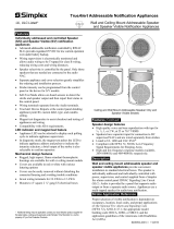
UL listed TrueAlert ES indoor product identification reference
Mounting instructions
1. Select the desired location and install the electrical box using screws suitable for the mounting surface.
2. Connect the building wires to the terminal block on the rear of the appliance. See Wiring instructions on page 2.
3. Secure the appliance to the electrical box by using the provided hardware.
4. Set the appliance settings. See Setting the address DIP switch on page 3.
5. Attach the cover to the appliance.
Type Cover colors Models Operation
Ceiling Mount
Speaker/Visible
(S/V)
Red
White
Black
Components:
49SV-APPLC
49HFV-APPLC
49SV-APPLC-BA
49HFV-APPLC-BA
49SVH-APPLC-BA
49HFVH-APPLC-BA
49SVH-APPLC
49HFVH-APPLC
Covers:
49SVC-CK
49SVC-CRALT
49SVC-CRFIRE
49SVC-CRS
49SVC-CRBC
49SVC-CWBC
49SVC-CWFIRE
49SVC-CRFEU
49SVC-CRBF
49SVC-CWALT
49SVC-CWBA
49SVC-CRBA
49SVC-CWS
49SVC-CWBF
49SVC-CWFEU
These appliances provide an audio (SO) or
audible/visible (S/V) warning of an alarm
condition when activated from the control
panel of a compatible UL/ULC Listed,
Simplex Fire Alarm System. Consult Simplex
Fire Alarm panel documentation for
compatibility information.
Speakers may be turned ON/OFF
individually under control of a compatible
panel.
S/V models ‘49HFV’ have Hi intensity
strobes; models ‘49SV’ have standard range
strobes.
Ceiling Mount
Speaker Only
(SO)
Red
White
Black
Components:
49SO-APPLC
49HF-APPLC
49SO-APPLC-BA
49HF-APPLC-BA
Covers:
49SOC-CK
49SOC-CW
49SOC-CR
49SOC-CWALT
49SOC-CRALT
49SOC-CRFIRE
49SOC-CRS
49SOC-CWFIRE
49SOC-CWS
Note: For information on appliance testing consult TrueAlert ES Addressable Appliances Troubleshooting Guide (579-1049).
Kit contents: Appliance (x1): with 8-32 1 in mounting screws (x2).
Tightening torque: 12-15 in/lbs, do not over tighten.
Not included:
Order a cover separately for each appliance.
Electrical box: 4 in square, 2-1/8 in minimum depth required.
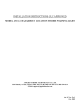
Figure 1. Mounting instructions
Cover
S/V Appliance
4 in. x 4 in. Electrical Box (2-1/8 in. deep)
Screws
-Use 8-32 screws for a 4 in. x 4 in. electrical box
Cover
SO Appliance
4 in. x 4 in. Electrical Box (2-1/8 in. deep)
-Use 8-32 screws for a 4 in. x 4 in. electrical boxScrews
Document: Installation Instructions
Product: TrueAlert ES Addressable
Ceiling Mount Speaker Indoor
Notification Appliances

2
579-1203 Installation Instructions
Wiring instructions
1. At the electrical box, connect the building wiring to the CKT + and CKT - terminals on the backplate.
2. Torque terminal block screws 12-15 inch-pounds to ensure proper continuity.
3. Ensure that correct polarity is maintained for each strobe unit.
4. Signal line circuit (SLC) wiring must be twisted pair (TWP). CKT Terminals accept two Wires: 12-18 American wire gauge (AWG)
TWP .
Wiring Notes
WARNING: Make sure that all power is disconnected before starting the installation.
IMPORTANT: Do not bring conduit through the rear of the electrical box. Strip lead insulation to 7/16 inch maximum.
Figure 2. Wiring instructions
1. Assign a maximum of 127 active appliances to a circuit. Assign a maximum of 51 active strobe appliances to a powered circuit. The maximum wire
resistance between appliances is 26
ohms. Refer to the Field Wiring Diagrams of the driving compatible fire alarm control panel for further
instructions.
2. Notification appliances are rated using an individual module label.
3. Maintain the correct polarity on the terminal connections.
4. Terminals 1 through 4 can each accommodate two wires, one wire going in and one wire going out to the next appliance.
5. These appliances are rated to the operating voltage limits of 23-30
volts DC (VDC). The appliance may fail to operate as intended, and may cause
permanent damage to this equipment if it operates outside of these limits.
6. The TrueAlert IDNAC S/V and SO can only be operated through a compatible power supply and amplifier.
7. T-tapping is not allowed for Class A wiring.
8. TrueAlert SLC wiring connections are supervised and power-limited.
!
S/V Appliance Back Side
Terminal 1: ‘NAC+’
Terminal 2: ‘NAC-’
Terminal 3: ‘Audio+’
Terminal 4: ‘Audio-’
(T-tapping example)
Class A Wiring (See Notes)
From Compatible SLC
Controller (See Notes)
Audio - Audio +
12
SLC +
CKT CKT
S/V, S/O
34
Audio -
Audio +
12
SLC - SLC +
CKT CKT
S/V, S/O
34
SLC -
Audio -
Audio +
To Next Appliance
or Compatible SLC
Controller
(See Notes)
Audio -
Audio +
12
SLC - SLC +
CKT CKT
S/V, S/O
34
Audio -
Audio +
12
CKT
S/V, S/O
34
Audio -
Audio +
12
SLC -
SLC +
CKT
S/V, S/O
34
Audio -
Audio +
12
SLC -
SLC +
CKT
S/V, S/O
34
Audio -
12
SLC -
SLC +
CKT
S/V, S/O
34
Audio +
Audio -
Audio +
From Amplifier
Audio +
Audio -
Class B Wiring (See Notes)
From Compatible SLC
Controller (See Notes)
From Amplifier
Audio +
Audio -
SO Appliance Back Side
Terminal 1: ‘NAC+’
Terminal 2: ‘NAC-’
Terminal 3: ‘Audio+’
Terminal 4: ‘Audio-’
P2
J2
1
P2
J2
1
P2/J2
P2/J2

3
579-1203 Installation Instructions
Setting the address DIP switch
Each addressable TrueAlert IDNAC notification appliance has a unique address that is set using an eight-position DIP switch
(ADDR1). Up to 127 unique addresses can be assigned to an SLC; however, total appliance loading available may be less due to
appliance current requirements.
To set the address
1. Unclip the cover from the appliance by inserting a slotted screwdriver (or similar sized object) into the opening at either end of the
cover. See Figure 3.
2. Use a small screwdriver or pen to set the switches.
3. Record the set address.
4. DIP switch position 8 determines whether this appliance is viewed by the system as an 'ALARM' (OFF) or 'ALERT' (ON) type
appliance. Confirm the setting for the appliance at this address with the FACP system configuration documentation.
Figure 3. Setting the DIP switch address
Setting the strobe candela setting
Figure 4. Setting the strobe and appliance
configuration
1. Jumpers are factory set as FACP. Leave the appliance at this setting if
the candela setting is to be programmed from a 4100ES FACP. The
candela setting is visible through the slot on the side of the case.
2. If manual selection is required, remove the cover and slide the CD
selector to the required setting: FACP or 15/30/75/110 for standard
strobe, FACP or 185/135/110 for HiCD strobe.
3. When the appliance is mounted, the candela rating is visible through the
side-window of the appliance.
Note: One of the 4 candela outputs must be programmed for each appliance by
authorizing service personnel or a programming mismatch trouble will result.
To set the candela through the Programmer set it to FACP. Additional
information is contained in the 4100ES Programmer’s Manual (574-849).
Audio circuit configuration (S/V and SO)
Use the slide switches depicted in Figure 4 for required audio circuit
voltage and power tap selection.
Move jumper P2, on the PCB on the back-side of the unit, to position 2-3
for 70 V/2 W operation. Use position 1-2 for all other audio levels, see
Figure 4.
To Access Switches:
SO Appliance
S/V Appliance
ALARM/
ALERT
001
101
011 111
64
65
66
67
68
69
70
71
72
73
74
75
76
77
78
79
80
81
82
83
84
85
86
87
88
89
90
91
92
93
94
95
96
97
98
99
100
101
102
103
104
105
106
107
108
109
110
111
112
113
114
115
116
117
118
119
120
121
122
123
124
125
126
127
DIP SWITCHES 5 THROUGH 7
000
100 010
110
Hgh Candela
Std Candela
Audio Circuit Conguration
P2
J2
1
P1
DEFAULT = 1-2
1-2 : 25V, 1/4W
2-3 : 70.7V, 2W
PCB on the back
side of the unit
P2
J2
1
DEFAULT = 1-2
1-2 : 25V, 1/4W
2-3 : 70.7V, 2W

579-1203 Installation Instructions
579-1203
Rev. B
R
Appliance specifications
Environmental specifications
Rated DC control/strobe
voltage range
Special application 23-30 VDC
Temperature range
32 °F to 120 °F (0 °C to 49 °C)
Humidity range
10 % to 93 %, non-condensing at
104 °F (40 °C)
Connections
Terminal for 18 AWG to 12 AWG
(0.82 mm
2
to 3.31 mm
2
)
CAUTION:
• The appliances are available in red and white. Do not paint
or otherwise alter the factory finishes in any way.
Maximum RMS operating current
49[SV/HFV] visible 49[SVH/HFVH] visible
Candela
Current
Candela
Current
15
59 mA - -
30
82 mA 110 235 mA
75
145 mA 135 255 mA
110
193 mA 185 295 mA
Speaker Only
SO 9 mA
Vertical and horizontal light dispersion ratings
(ceiling to walls and floors)
Percent of rated light output at any candela setting
(room temperature)
Vertical dispersion Horizontal dispersion
Y-plane
angle
UL req
output
Typical
output
X-plane
angle
UL Req
output
Typical
output
0
100
% 327 %
0
100 % 343 %
±5
90
% 293 %
±5
90 % 160 %
±10
90
% 281 %
±10
90 % 175 %
±15
90
% 197 %
±15
90 % 129 %
±20
90
% 168 %
±20
90 % 145 %
±25
90
% 142 %
±25
90 % 165 %
±30
45
% 143 %
±30
45 % 152 %
±35
45
% 155 %
±35
45 % 144 %
±40
45
% 156 %
±40
45 % 139 %
±45
45
% 134 %
±45
45 % 129 %
±50
55
% 115 %
±50
55 % 129 %
±55
45
% 104 %
±55
45 % 123 %
±60
40
% 103 %
±60
40 % 111 %
±65
35
%98 %
±65
35 % 120 %
±70
35
%87 %
±70
35 % 103 %
±75
30
%90 %
±75
30 %75 %
±80
30
%96 %
±80
30 %83 %
±85
25
%96 %
±85
25 %70 %
±90
25
%83 %
±90
25 %47 %
Speaker specifications
Input voltage 25 VRMS or 70.7 VRMS - speakers are for connection to compatible fire alarm audio circuits.
Power taps via jumper J1 1/4 W, 1/2 W, 1 W and 2 W
Frequency
Response
Fire alarm 400 Hz to 4000 Hz [SV/SO]; 200 Hz to 10000 Hz [HFV/HF]
General signaling 125 Hz to 12 kHz
TrueAlert Addressable Ceiling Mount S/V and SO units- speaker switch setting (25 V or 70 V audio)
-
Tap settings in
Watts
UL1480 at 10 ft ULC-S541 at 3 m
HiSPL (SV/SO)
models
HiFi (HFV/HF)
models
HiSPL (SV/SO)
models
HiFi (HFV/HF)
models
Speaker
Only
1/4 79 77 81 78
1/2 83 81 85 82
186 84 88 85*
290 87 91 88*
Speaker
Visible
1/4 79 76 79 78
1/2 83 80 83 82
186 84 86 85*
289 87 89 88*
Note:
• Reverberant dBA measurements are a minimum UL rating based on sound level measurements made in UL’s reverberant test chamber.
• Anechoic dBA measurements are a minimum ULC rating based on sound pressure level measurements made in ULC’s anechoic test chamber.
• The sound pressure level decreases by 3 dB at an angular displacement of 70° from the line perpendicular to the speaker’s center. The SPL
decreases by 6
dB at an angle of 80° from that line.
• Only marked settings may be used for ULC fire alarm applications.
/