Page is loading ...

Service Guide
SER 7492
7492
7498 7498-A
7498-B 7498-C
Alemite Corporation
167 Roweland Drive, Johnson City, Tennessee 37601
www.alemite.com
Copyright © 2004 by Alemite Corporation
This document contains confidential information that is the property of Alemite Corporation
670709 and is not to be copied, used, or disclosed to others without express written permission. Revision (10-04)
To latch the valve in the full open position, release
the lever (while pressing the button), then release the
button. To shut the valve off, press the lever and release.
NOTE: The latch feature can be disabled
with the removal of a roll pin.
See Figure 4.
Specifications
Fluid Inlet
(Swivel) Fluid Outlet
(at Valve Handle)
Max. Operating
Pressure
psi Bars
1/2 " NPTF (f) 1/2 " NPTF (f) 1500 103
Table 1 Model 7492 and 7498 Series Specifications
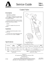
Description and Operation
The control valves included in models 7492 and 7498
series are designed to dispense a variety of lubricating fluids.
Each model of control valve contains a 40-mesh strainer.
Model 7492 and 7498 Series
The extension and nozzle on each model is designed for
different applications. Refer to Figures 1 and 2 for details.
Control Valve Operation
To begin, press the button in the center of the lever. This
releases the safety. With the button held, squeeze the lever to
open the valve.
Non-Metered Control Valve
Figure 1 Control Valve Model 7492 and 7498 Series - Model 7498-A Shown
Valve Model Extension Nozzle Type
7492 Rigid Non-Drip Automatic (with Manual Lock)
7498 Rigid Non-Drip Automatic
7498-A Flexible Non-Drip Automatic
7498-B (Obsolete) Rigid Non-Drip High-Volume Automatic
7498-C Non-Drip High-Volume Manual
Refer to Figure 2 for configuration on each model

SER 7492 Non-Metered Control Valve
Revision (10-04) 2 Alemite Corporation
Item
No. Part No. Description Qty Model and Notes Numeric Order
Part # (Item #)
1 338709 Hose, 1/2 " NPTf (m) x 1/4 " NPTF (m) 1 7498-A 51891 (4)
2 B339800 Non-Drip Nozzle, Automatic 1 7498, 7498-A 318400-2 (9)
3 339100 Handle Assembly, Control Valve 1 See Figure 4 320421 (8)
4 51891 Bushing, 1/2 " NPTf (m) x 1/4 " NPTF (f) 1 7492, 7498 332892 (6)
5 339149 Extension, Curved, 1/2 " NPTF (m) 1 7498-B, 7498-C 338702 (10)
6 Non-Drip Nozzle, High-Volume Automatic 1 Obsolete 338709 (1)
7 340084 Non-Drip Nozzle, High-Volume Manual 1 7498-C 339100 (3)
8 320421 Extension, Straight, 1/4 " NPTF (m) 1 7492 339149 (5)
9 318400-2 Non-Drip Nozzle, Automatic (w/ Manual Lock) 1 7492 B339800 (2)
10 338702 Extension, Curved, 1/4 " NPTF (m) 1 7498 340084 (7)
Figure 2 Control Valve Model 7492 and 7498 Series - Exploded View

Non-Metered Control Valve SER 7492
Alemite Corporation 3 Revision (10-04)

SER 7492 Non-Metered Control Valve
Revision (10-04) 4 Alemite Corporation
6. Remove V-Block (13) and Spring (15) from the Stem.
7. Unscrew Screw Assembly (19) from the Angle Body.
8. Remove Washer (18) from the Screw Assembly.
9. Remove Gasket (17) from the Angle Body.
Overhaul
NOTE: Refer to Figure 2 for component
identification on the major components of
the valve assembly.
Prior to performing any maintenance procedure, the
following safety precautions must be observed. Personal
injury may occur.
WARNING
Do not use halogenated hydrocarbon sol-
vents such as methylene chloride or 1,1,1 trichlo-
roethane in this valve assembly. An explosion can
result within an enclosed device capable of con-
taining pressure when aluminum and/or zinc-
plated parts come in contact with halogenated
hydrocarbon solvents.
Release all pressure within the system prior to
performing any overhaul procedure.
• Disconnect the air supply line from the pump
motor.
• Into an appropriate container, operate the
control valve to discharge remaining pressure
within the system.
Never point a control valve at any portion of your
body or another person. Accidental discharge of
pressure and/or material can result in personal
injury.
Read each step of the instructions carefully. Make
sure a proper understanding is achieved before
proceeding.
Disassembly
Non-Metered Control Valve
NOTE: The following procedures pertain to
all models of non-metered control valves.
1. Unscrew the extension assembly from Control Valve
Handle Assembly (3).
2. Separate the components of the extension assembly.
Non-Drip Nozzle (Automatic w/ Manual Lock)
3. Unscrew Nozzle (11) from Angle Body (16).
4. Remove O-Ring (12) from the Nozzle.
5. Remove Stem (14) from the Nozzle. Figure 3 Nozzle Assembly 318400-2 - Exploded View
Item
No. Description Notes Qty
11 Nozzle 1
12 O-Ring, 1/2 " ID x 5/8 " OD 1
13 V-Block 1
14 Stem 1
15 Spring 1
16 Body, Angle 1
17 Gasket 1
18 Washer 1
19 Screw Assembly 1
Legend:
Parts are not available separately
designates a repair kit item
Repair Kit
Part No. Kit Symbol Description
393518 Kit, Repair

Non-Metered Control Valve SER 7492
Alemite Corporation 5 Revision (10-04)
Control Valve Handle
NOTE: Refer to Figure 4 for component
identification.
1. Unscrew Swivel Assembly (29) from Body (20).
2. Remove O-Ring (28) from the Swivel Assembly.
3. Remove Strainer (27), Compression Spring (26), and
Spring Support (25) from the Body.
4. Remove Small Compression Spring (24), Seal (23),
and Push Rod (22) from the Body.
5. Remove Screws (39) that secure Lever Assembly (38)
to Cam (41).
• Remove the Lever Assembly from the Cam.
NOTE: The Lever Assembly is serviced as
an assembly.
6. Remove the Cam from the Body.
7. Remove O-Rings (32) from the Cam.
8. Remove Roll Pin (21) from the Body as required.
Clean and Inspect
NOTE: Use a repair kit for replacement
parts. Make sure all the components are
included in the kit before discarding used
parts.
1. Clean all metal parts in cleaning solvent. The solvent
should be environmentally safe.
2. Inspect all parts for wear and/or damage.
• Replace as necessary.
3. Closely inspect the mating surfaces of all components
for any imperfections. Ensure a smooth and clean
contact is obtained when assembled.
Assembly
NOTE: Prior to assembly, certain compo-
nents require lubrication. Refer to Table 2
for details.
Control Valve Handle
NOTE: Refer to Figure 5 for a section
view of the control valve handle assembly.
1. Install Roll Pin (21) into Body (20) as required.
IMPORTANT: Lubricate O-Rings (32)
with grease prior to installation.
2. Install O-Rings (32) onto Cam (33).
3. Install the Cam assembly into the Body.
• Make sure to orient the Cam as shown in Figure 4.
4. Position Lever Assembly (30) onto the tabs of the
Cam.
• Make sure the safety does not interfere with the
Body.
5. Install Screws (31) that secure the Lever Assembly
to the Cam.
• Tighten the Screws securely.
6. Install Seal (23) [blunt end first] onto Push Rod
(22).
7. Install Spring Support (25) into the small end of
Compression Spring (26).
8. Install Small Compression Spring (24) onto the
Spring Support.
9. Install the Push Rod and Seal assembly onto the
Spring Support.
10. Install the Compression Spring (with assembled
components) into the Body.
• Make sure the Push Rod seats properly on the
Cam.
11. Install Strainer (27) into the Compression Spring.
12. Install O-Ring (28) onto Swivel Assembly (29).
NOTE: Swivel Assembly is under Spring
pressure during installation.
13. Screw the Swivel Assembly into the Body.
• Tighten the Swivel Assembly securely.
Item No. Description
Clean Oil
12 O-Ring, 1/2 " ID x 5/8 " OD
28 O-Ring, 13/16 " ID x 1 " OD
Multi-Purpose Grease
32 O-Ring, 1/2 " ID x 11/16 " OD
Table 2 Lubricated Components

SER 7492 Non-Metered Control Valve
Revision (10-04) 6 Alemite Corporation
Figure 4 Control Valve Handle 339100 - Exploded View
Item
No. Part No. Description Qty Notes Numeric Order
Part # (Item #)
20 Body 1 (30)
21 Pin, Roll, 1/8 " x 5/8 " Long 1 X171000-10 (32)
22 Rod, Push 1 X171009-17 (28)
23 Seal 1 171033-5 (21)
24 Spring, Compression, Small 1 339055 (33)
25 Support, Spring 1 339056 (22)
26 339063 Spring, Compression 1 339063 (26)
27 339064 Strainer (40-Mesh) 1 339064 (27)
28 X171009-17 O-Ring, 13/16 " ID x 1 " OD 1 339066 (20)
29 339656 Swivel Assembly 1 339067 (25)
30 Lever Assembly 1 339068 (24)
31 Screw, 10 -24 x 3/8 " 2 339069 (23)
32 X171000-10 O-Ring, 1/2 " ID x 11/16 " OD 2 339070 (31)
33 339055 Cam 1 339656 (29)
Legend:
Part numbers left blank (or in Italics) are not serviced separately
Part numbers with an X prefix indicate a quantity of ten (10)
designates a repair kit item
Repair Kits
Part No. Kit Symbol Description
393676 Kit, Major Repair
393677 Kit, Lever Replacement

Non-Metered Control Valve SER 7492
Alemite Corporation 7 Revision (10-04)
Refer to Figure 5 Parts List
for Parts Identification
Non-Drip Nozzle (Automatic w/ Manual Lock)
NOTE: Refer to Figure 3 for component
identification.
14. Install Gasket (17) into Angle Body (16).
15. Install Washer (18) into Screw Assembly (19).
16. Thread the Screw Assembly into the Angle Body.
• Tighten the Screw Assembly securely.
17. Install O-Ring (12) onto Nozzle (11).
18. Install and seat V-Block (13) [concave first] onto the
pointed end of Stem (14).
19. Install the Stem assembly [point first] into the Nozzle.
20. Install Spring (15) into the Stem.
21. Screw the Nozzle assembly into Angle Body.
• Tighten the Nozzle securely.
Non-Metered Control Valve
IMPORTANT: Apply thread sealant to all
pipe thread connections prior to assembly.
1. Connect the components of the extension assembly
and tighten securely.
2. Screw the extension assembly into Control Valve
Handle Assembly (3).
• Tighten the extension securely.
Installation
Attach the Swivel Assembly [with thread sealant] to its
delivery line. Tighten the connection securely.
Operation
WARNING
Should leakage occur anywhere within the
system, disconnect power to the motor. Personal
injury can occur.
Safety and Latch
1. Squeeze the Lever to ensure the safety engages
properly.
2. Press the button in the center of the Lever and operate
the Lever. The Lever should move to the open
position.
3. Release the Lever (while pressing the button) then
release the button to ensure the latch engages properly.
4. Press the Lever and release to release the latch.
If the safety and/or latch does not operate properly,
refer to the Troubleshooting Chart.
Figure 5 Control Valve Handle 339100 - Section View

SER 7492 Non-Metered Control Valve
Revision (10-04) 8 Alemite Corporation
Prime and Test
NOTE: Perform the following procedures at
an air pressure that allows the pump to begin
to cycle. Regulate the amount of air to the
pump with a pressure regulator.
Should valve leakage occur at anytime, refer
to the Troubleshooting Chart.
1. Point the control valve into an appropriate collection
container.
2. Allow the pump to deliver fluid to the control valve.
• The control valve should show no leakage nor
dispense the product.
3. Cycle the control valve Lever Assembly several times.
• Product should flow once air is eliminated from the
control valve (and system).
If the control valve does not dispense the product, refer
to the Troubleshooting Chart.
With the Lever in the released position, no product
should appear at the Nozzle. If product does appear, refer
to the Troubleshooting Chart.
Troubleshooting Chart
Control Valve Indications Possible Problems Solutions
Continuous product flow 1. Foreign material on Seal (31)
2. Seal (31) worn or damaged
1. Disassemble, clean, and inspect
seat area. Check mating surfaces
and replace Seal (31) as necessary.
Locate and eliminate source of
foreign material.
Clean Strainer (35)
2. Use Kit 393676
No product flow Manual Nozzle (7 or 9) not open Open Nozzle (7 or 9)
Leakage at Swivel
Assembly (37)1. Initial tightening of Swivel Assembly (37)
not sufficient
2. O-Ring (36) worn or damaged.
1. Tighten Swivel Assembly (37)
2. Replace O-Ring (36)
Leakage at Cam (41) O-Rings (40) worn or damaged. Replace O-Rings (40)
Leakage at front end of Nozzle Nozzle damaged Replace Nozzle
Leakage at Extension Assembly 1. Initial tightening not sufficient
2. Thread sealant missing or inadequate 1. Tighten leaking connection
2. Apply thread sealant* to male pipe
threads
Safety on Lever Assembly (38)
does not engage 1. Broken spring in Lever Assembly (38)
2. Foreign material in Lever Assembly (38)
3. Worn or damaged Compression Spring (34)
1. Use Kit 393677
2. Clean Lever Assembly (38)
3. Replace Compression Spring (34)
Latch on Lever Assembly (38)
does not release 1. Broken spring in Lever Assembly (38)
2. Foreign material in Lever Assembly (38)
3. Worn or damaged Compression Spring (34)
1. Use Kit 393677
2. Clean Lever Assembly (38)
3. Replace Compression Spring (34)
* Do not apply thread sealant to the first two (2) threads. Contamination can occur.
Changes Since Last Printing
Added Model 7492-C
/