Page is loading ...

Quick‐
start
Q U I C K S T A R T e n
1 About this document
The purpose of this Quickstart is to allow you to commission the product quickly
and easily.
Supplementary and other relevant documents:
•
Radar sensor safety notes (no. 8021532), printed copy included
•
RMS3xx operating instructions (German: no. 8021529, English:
no. 8021530), available to download from the Internet
•
RMS3xx “Regulatory Notes” technical information (no. 8021596), printed
copy included
•
Telegram Listing RMS3xx, (English: no. 8021531), available to download
from the Internet
These documents (available for download) and additional information, such as
application examples and associated software, can be found on the SICK product
page on the Internet at: www.sick.com/RMS3xx
All rights reserved. Subject to change without notice.
2 Safety information
2.1 Intended use
The RMS3xx radar sensor is used for area monitoring. Within a defined detection
area, the sensor detects static and moving objects, and triggers a switching signal
upon detection of a corresponding object.
Distance zones can be defined and these zones can be assigned various func‐
tions.
The distance of the objects, the speed and the direction of the movement within
the detection area are calculated and provided via the data telegram.
All object data can be provided via Ethernet, or via the CAN protocol.
The SOPAS_ET software from SICK AG must be used to operate the RMS3xx.
NOTE
The radar sensor is approved for operation in countries listed in the RMS3xx
"Regulatory Notes" technical information (no. 8021596). This document is
included with the device. The operation of the device in other countries can
interfere with protected frequency ranges.
•
Only use the device in countries in which it has been approved.
•
When reselling the device, inform the buyer about the regional approval
restrictions.
SICK AG assumes no liability for losses or damage arising from the use of the
product, either directly or indirectly. This applies in particular to use of the product
that does not conform to its intended purpose and is not described in this docu‐
mentation.
3 Product description
3.1 Scope of delivery
The delivery of the device includes the following components:
Piece Component Comment
1 Device in the version ordered Without connecting cables and brackets
1 Set of protective caps for elec‐
trical connections
Included or possibly attached to the device
1 Printed RMS3xx "Regulatory
Notes" technical information
(no. 8021596)
Informs about the countries for which an approval
exists; names country-specific aspects which are
to be taken into account during operation of the
RMS3xx.
1 Printed safety notes, multilin‐
gual (no. 8021532)
Informs about the requirements for safe use of the
product.
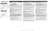
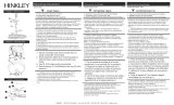
3.2 Status indicators
Status indicators: A
LED Light pattern / color Description
Power - / - Device off
O / yellow
Initialization phase
O / green
Device is ready
Ö / red
Device error
Ö / violet
Firmware update in progress
Ö / green
Firmware update complete
I/O
O / green
No field violation
LED Light pattern / color Description
O / yellow
Information field violation
O / red
Warning field violation
Link - /- No connection
O / green
Ethernet connection
Ö / green
Data transmission via Ethernet con‐
nection
O / yellow
CAN connection
Ö / yellow
Data transmission via CAN connec‐
tion
Ö = illuminated; Ö = flashing
4 Mounting
4.1 Mounting instructions
•
Observe the technical data.
•
Protect the sensor from direct sunlight.
•
To prevent condensation, avoid exposing the sensor to rapid changes in tem‐
perature.
•
The mounting site has to be designed for the weight of the device.
•
It should be mounted so that it is exposed to as little shock and vibration as
possible. Optional mounting accessories are available, see Accessories,
page 2.
•
Use of a weather hood and a mounting bracket is recommended for outdoor
installations. Information about optional accessories, Accessories,
page 2.
5 Electrical installation
5.1 Wiring notes
NOTE
Preassembled cables can be found online at:
•
www.sick.com/RMS3xx
NOTICE
Faults due to incorrect wiring.
Incorrect wiring may result in operational faults.
•
Follow the wiring notes precisely.
•
Connect the connecting cables in a de-energized state. Switch on the supply
voltage only after complete installation/connection of all connecting cables
to the device and control system.
•
The wires of unused switching outputs must be insulated at the control cabi‐
net.
•
Use proper connecting cables and male connectors for the application/envi‐
ronment, see Accessories, page 2.
•
The specified device enclosure rating is valid only with suitable mating con‐
nectors or with the protective caps installed.
•
Electrical protection class III / SELV supply voltage.
•
The supply voltage must be as specified in the technical data.
•
The voltage supply or power supply unit must satisfy SELV requirements in
accordance with the currently applicable EN 60950-1 (SELV = Safety Extra
Low Voltage).
•
The voltage supply via a power supply unit must be capable of buffering a
brief mains voltage failure of 20 ms.
•
Prevent product damage caused by short-circuit: The device supply voltage
input is equipped with reverse polarity protection. The internal functional
ground, which also corresponds to the negative pole of the supply voltage for
the device, is connected directly to the metal housing of the device.
5.2 Connection diagram
Ethernet
Pin assignment for Ethernet connection
Male/female
connector
Pin Short form Signal description
M12 female
connector, 4-pin
D-coded
1
43
2
1 TX+ Transmit data positive
2 RX+ Receive data positive
3 TX- Transmit data negative
4 RX- Receive data negative
CAN
Pin assignment for CAN connection
Male/female
connector
Pin Short form Signal description
M12 male con‐
nector, 8-pin A-
coded
1 CAN H CAN high
2 CAN L CAN low
3 IN2 Input 2
4 GND IN1/2 Earth input 1/2
8023323//2018-07-30/en, de, es, pt, ko RMS3xx | SICK 1
8023323//2018-07-30
www.sick.com
RMS3xx
SICK AG
E
rwin-Sick
-Straße 1
D-79183 Waldkirch

Male/female
connector
Pin Short form Signal description
1
7
2
6
3
4
5
8
5 OUT2 Output 2
6 OUT3 Output 3
7 GND Earth
8 OUT4 Output 4
Power
Pin assignment Power connection
Male/female
connector
Pin Short form Signal description
M12 male con‐
nector, 5-pin A-
coded
1
4 3
5
2
1 L+ Supply voltage: +9.5 … +36 V DC
2 LIN1 Input 1
3 GND Earth
4 OUT1 Output 1
5 GND IN1/2 Earth input 1/2
5.3 Connecting the device electrically
1. Ensure the voltage supply is not connected.
2. Connect the device according to the connection diagram, Connection dia‐
gram, page 1.
RMS3xx connection overview: B
3. Switch on the supply voltage.
✓ The initialization phase starts, the Power LED lights up yellow. As soon as the
Power LED lights up green, the device is ready for operation.
6 Operation
6.1 General advice
The device works fully automatically in normal operation and requires no operator
intervention.
6.2 Switching on / Switching off
1. Disconnect the device from the voltage supply to switch it off.
✓ The device switches off. The device configuration remains unchanged, mea‐
sured values are lost.
2. Connect the device to the voltage supply.
✓ The device starts with the last saved configuration data.
7 Technical data (excerpt)
NOTE
The relevant online data sheet for your product, including technical data,
dimensional drawing, and connection diagrams, can be downloaded, saved,
and printed from the Internet:
•
www.sick.com/RMS3xx
7.1 Features
Measurement principle FMCW
Radio equipment
approval
See “Regulatory Compliance Information” technical information
(no. 8021596) included with the product
Frequency band 24.05 GHz … 24.25 GHz
Transmitting power +12.7 EIRP(dBm)
Aperture angle ± 8° vertical
± 50° horizontal
Operating range 1 m … 45 m
1
20 m typical (1 m² RCS
2
)
40 m typical (10 m² RCS
3
)
1
Under 1 m, only presence detection
2
Typical radar cross section value for a pedestrian
3
Typical radar cross section value for a car
7.2 Mechanics/electronics
Dimensional drawing
Dimensional drawing RMS3xx (dimensions in mm (inch)): C
8 Accessories
NOTE
Accessories and where applicable mounting information can be found online
at:
•
www.sick.com/RMS3xx
Q U I C K S T A R T d e
1 Zu diesem Dokument
Dieser Quickstart dient dazu, das Produkt schnell und einfach in Betrieb zu neh‐
men.
Ergänzende und mitgeltende Dokumente:
•
Safety Notes Radarsensoren (Nr. 8021532), gedruckt beiliegend
•
Betriebsanleitung RMS3xx (Deutsch: Nr. 8021529, Englisch: Nr. 8021530),
im Internet zum Download
•
Technische Information RMS3xx "Regulatorische Hinweise" (Nr. 8021596),
gedruckt beiliegend
•
Telegram Listing RMS3xx (Englisch: Nr. 8021531), im Internet zum Down‐
load
Diese Dokumente (zum Download) und weitere Informationen wie z. B. Anwen‐
dungsbeispiele und zugehörige Software finden Sie auf der SICK-Produktseite im
Internet unter: www.sick.com/RMS3xx
Alle Rechte vorbehalten. Irrtümer und Änderungen vorbehalten.
2 Zu Ihrer Sicherheit
2.1 Bestimmungsgemäße Verwendung
Der Radarsensor RMS3xx dient zur Bereichsüberwachung. Der Sensor erkennt in
einem definierten Erfassungsfeld statische und bewegte Objekte und löst bei
Erkennung eines entsprechenden Objekts ein Schaltsignal aus.
Distanz-Zonen können definiert werden und diesen Zonen verschiedene Funktio‐
nen zugewiesen werden.
Die Distanz der Objekte, die Geschwindigkeit und die Richtung der Bewegung
innerhalb des Erfassungsbereichs wird berechnet und über das Daten-Telegramm
bereitgestellt.
Alle Objektdaten können über Ethernet bereitgestellt werden, ebenso ist eine
Bereitstellung über das CAN-Protokoll möglich.
Zur Bedienung des RMS3xx muss die Software SOPAS_ET der SICK AG verwendet
werden.
HINWEIS
Der Radarsensor ist zum Betrieb in den Ländern zugelassen, die in der Tech‐
nischen Information RMS3xx "Regulatorische Hinweise" (Nr. 8021596) gelis‐
tet sind. Dieses Dokument liegt dem Gerät bei. Bei Betrieb des Geräts in
anderen Ländern können geschützte Frequenzbereiche gestört werden.
•
Gerät nur in Ländern betreiben für die eine Zulassung vorliegt.
•
Beim Weiterverkauf des Geräts den Käufer über die regionalen Zulas‐
sungesbeschränkungen informieren.
Die SICK AG übernimmt keine Haftung für direkte oder indirekte Verluste oder
Schäden, die aus der Benutzung des Produkts resultieren. Dies gilt insbesondere
für eine andersartige Verwendung des Produkts, die nicht mit dem beabsichtigten
Zweck übereinstimmt und die nicht in dieser Dokumentation beschrieben ist.
3 Produktbeschreibung
3.1 Lieferumfang
Die Lieferung des Geräts umfasst folgende Komponenten:
Stück Komponente Bemerkung
1 Gerät in der bestellten Ausfüh‐
rung
Ohne Anschlussleitungen und Halterungen
1 Satz Schutzkappen für elektri‐
sche Anschlüsse
Beigelegt oder ggf. angebracht
1 Gedruckte Technische Informa‐
tion RMS3xx "Regulatorische
Hinweise" (Nr. 8021596)
Informiert über die Länder, für die eine Zulassung
vorliegt; nennt länderspezifische Besonderheiten,
die beim Betrieb des RMS3xx zu berücksichtigen
sind.
1 Gedruckte Safety Notes, mehr‐
sprachig (Nr. 8021532)
Informiert über die Voraussetzungen für eine
sichere Verwendung des Produkts.
3.2 Anzeigeelemente
Anzeigeelemente: A
LED Leuchtmuster / Farbe Beschreibung
Power - / - Gerät aus
O / gelb
Initialisierungsphase
O / grün
Gerät betriebsbereit
Ö / rot
Gerätefehler
Ö / violett
Firmwareupdate läuft
Ö / grün
Firmwareupdate abgeschlossen
I/O
O / grün
keine Feldverletzung
O / gelb
Feldverletzung Informationsfeld
O / rot
Feldverletzung Warnfeld
Link - /- keine Verbindung
O / grün
Ethernet-Verbindung
Ö / grün
Datenübertragung über Ethernet-
Verbindung
O / gelb
CAN-Verbindung
Ö / gelb
Datenübertragung über CAN-Verbin‐
dung
O = leuchtet; Ö = blinkt
8023323//2018-07-30/en, de, es, pt, ko RMS3xx | SICK 2
/