Page is loading ...

start here commencez ici
empezar aquí
Assembly Instructions
Item No: 3691
-CL
Les Instructions D’assemblage
Numéro d’article: 3691
-CL
Instrucciones De Montaje
Número del artículo: 3691
C-CL
English Spanish French
NOT PROVIDED
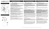
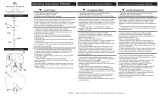
NOTE: THE MOUNTING PLATE FOR YOUR FIXTURE IS DESIGNED WITH
ADDITIONAL ANCHOR HOLES (S) TO PROVIDE ADDITIONAL SUPPORT,
WHEN MOUNTED TO A JUNCTION BOX - SEE
DRAWING 1.
PLEASE USE APPROPRIATE ANCHORING HARDWARE FOR THE MATERI-
AL YOU ARE MOUNTING TOO. IT IS HIGHLY RECOMMENDED TO ADD THE
ADDITIONAL SUPPORT.
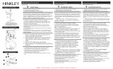
3. Make all wiring connections using IS-18
MOUNTING BACKPLATE TO THE MOUNTING PLATE
SAFETY WARNING: READ WIRING AND GROUNDING INSTRUC-
TIONS (I.S. 18) AND ANY ADDITIONAL DIRECTIONS. TURN POWER
SUPPLY OFF DURING INSTALLATION. IF NEW WIRING IS
REQUIRED, CONSULT A QUALIFIED ELECTRICIAN OR LOCAL
B
C
D
BW
WW
A
N
S
JS
E
F
NOTA: LA PLACA DE MONTAJE PARA SU ARTEFACTO ESTÁ DISEÑADA
CON AGUJEROS DE ANCLAJE ADICIONALES PARA PROPORCIONAR
SOPORTE ADICIONAL, CUANDO SE MONTA EN UNA CAJA DE
CONEXIONES - VER
DIBUJO 1.
POR FAVOR UTILICE HERRAJES DE ANCLAJE APROPIADOS PARA EL
MATERIAL QUE ESTÁ MONTANDO TAMBIÉN. ES MUY RECOMENDABLE
AGREGAR EL SOPORTE ADICIONAL.
3. Realice todas las conexiones de cableado utilizando IS-18
REMARQUE : LA PLAQUE DE MONTAGE POUR VOTRE LUMINAIRE EST
CONÇUE AVEC DES TROUS D'ANCRAGE SUPPLÉMENTAIRES POUR
FOURNIR UN SUPPORT SUPPLÉMENTAIRE, LORSQU'ELLE EST MONTÉE
SUR UNE BOÎTE DE JONCTION - VOIR
DESSIN 1.
VEUILLEZ UTILISER LE MATÉRIEL D'ANCRAGE APPROPRIÉ POUR LE
MATÉRIEL QUE VOUS MONTEZ AUSSI. IL EST FORTEMENT RECOMMANDÉ
D'AJOUTER LE SUPPORT SUPPLÉMENTAIRE.
3. Effectuez toutes les connexions de câblage à l'aide de l'IS-18
ADVERTENCIA DE SEGURIDAD: LEA LAS INSTRUCCIONES DE CABLEADO
Y CONEXIÓN A TIERRA (I.S. 18) Y CUALQUIER INSTRUCCIONES ADICIONA-
LES. APAGUE LA FUENTE DE ALIMENTACIÓN DURANTE LA INSTALACIÓN.
SI SE REQUIERE NUEVO CABLEADO, CONSULTE A LAS AUTORIDADES
ELECTRICAS O LOCALES CUALIFICADAS PARA REQUISITOS DE CÓDIGO.
AVERTISSEMENT DE SÉCURITÉ: LISEZ LES INSTRUCTIONS DE CÂBLAGE ET
DE MISE À LA TERRE (I.S. 18) ET TOUTE AUTRE INSTRUCTION. COUPEZ
L'ALIMENTATION PENDANT L'INSTALLATION. SI UN NOUVEAU CABLAGE
EST NÉCESSAIRE, CONSULTER UN ÉLECTRICIEN QUALIFIÉ OU LES
AUTORITÉS LOCALES POUR LES EXIGENCES DU CODE.
PLACA DE MONTAJE EN LA PLACA DE MONTAJE MONTAGE DE LA PLAQUE ARRIÈRE SUR LA PLAQUE DE MONTAGE,
H
I
N
K
L
E
Y
H I N K L E Y 33000 Pin Oak Parkway A

start here commencez ici
empezar aquí
Assembly Instructions
Item No: 3691 - CL
Les Instructions D’assemblage
Numéro d’article: 3691 - CL
Instrucciones De Montaje
Número del artículo:
3691 - CL
English Spanish French
H
I
N
K
L
E
Y
H I N K L E Y 33000 Pin Oak Parkway A
HK
AR
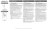
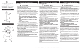
1. To attach glass shade, first remove threaded socket ring
(r) from socket (s) along with spacer (t) - see Drawing 1.
2. Next slip center hole of glass shade (g), over threaded
portion of socket (s), and hold in position.
3. Now slip spacer over socket and then thread socket ring
(r) onto socket to secure shade.
tr
g
s
1. Para colocar la pantalla de vidrio, primero retire el
anillo roscado (r) de los enchufes junto con el espa-
ciador (t); consulte el dibujo 1.
2. A continuación, deslice el orificio central de la pan-
talla de vidrio (g) sobre la parte roscada de los
receptáculos y manténgalo en posición.
3. Ahora deslice el espaciador sobre el casquillo y
luego enrosque el anillo del casquillo (r) en el casquillo
para asegurar la cortina.
1. Pour fixer l'abat-jour en verre, retirez d'abord l'an-
neau de douille fileté (r) de la ou des douilles avec
l'entretoise (t) - voir dessin 1.
2. Glissez ensuite le trou central de l'abat-jour en verre
(g), sur la partie filetée de la ou des douilles et main-
tenez-le en place.
3. Glissez maintenant l'entretoise sur la douille, puis
vissez la bague de douille (r) sur la douille pour fixer le
store.
NOTE: please note that the glass shade is hand blown. There may
be variations in the glass thickness. It may be necessary in some
cases to remove ring (t). In order for the socket ring (r) to thread
on properly.
NOTA: tenga en cuenta que la pantalla de vidrio está
soplada a mano. Puede haber variaciones en el espesor
del vidrio. En algunos casos, puede ser necesario quitar el
anillo (t). Para que el anillo de enchufe (r) se enrosque
correctamente.
REMARQUE: veuillez noter que l'abat-jour en verre est
soué à la main. Il peut y avoir des variations dans
l'épaisseur du verre. Il peut être nécessaire dans certains
cas de retirer l'anneau (t). Pour que l'anneau de douille (r)
s'enle correctement.

I.S. 18 wiring grounding instructions
SAFE TY WARNI NG: READ WIRIN G AND GR OUNDING
INSTRUCTIO NS (IS 18) AND ANY ADDITIONAL DIRECTIONS.
TURN POWER SUPPLY OFF DURING INSTALLATION. IF NEW
WIRING IS REQUIRED, CONSU LT A QUALIFIED ELECTRICIAN OR
LOCAL AUTHORITIES FOR CODE REQUIREMENTS
wiring instructions
Indoor Fixtures
1. Connec t positi ve supply w ire (A ) (typical ly black or the smoo th,
unma rked side of the two-conduc tor cord) to positi ve fi xture lead (B )
with appropriately sized t wist on connec tor - see Dra w ings 1 o r 2.
2. Connec t nega ti ve supp ly wi re (C) (typica lly whi te or the ribbed , marked
side of the two-conduc tor cord) to negative fi xture lead (D).
3. Ple ase refe r to the groundin g instructions below to complet e all
electrical connec tion s
Outdoor Fixtures
1. Connec t positi ve supply w ire (A ) (typical ly black or the smoo th
unma rked side of the two-conduc tor cord) to positi ve fi xture lead (B)
with appropriately sized twist on connec tor --- see Draw ings 2 or 3.
2. Connec t nega ti ve supp ly wi re (C) (typica lly whi te or the ribbed , marked
side of the two-conduc tor cord) to negative fi xture lead (D).
3. Cove r open end of connec tor s wit h silicone sealant to fo rm a
wate rtight seal.
If installing a wall moun t fi xture, use caulk to seal gaps between the
fi xture mounting p late (backpla te) and the wall. This w ill help prevent
wa ter fr om entering the out let box . If the wal l surf ace is lap siding, use
cau lk and a fi xture moun ti ng plat form specially.
4. Ple ase refe r to the grounding in structions below to complet e all
electrical connec tion s.
grounding instructions
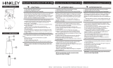
Flush Mount Fixtur es
For positive ground ing in a 3-wire elect rical system, f asten the fi xture
ground w ir e ( E) (typ ically coppe r or green plasti c coated) to the fi xture
moun ti ng strap (M ) with the ground screw ( S) - see Dr aw in g 1 .
Note: On straps for screw supported fixtures, first install the two mounting
screws in strap. Any remaining tapped hole may be used for the ground screw.
Chain Hung Fixtur es
Loop fi xture ground w ir e ( E ) (typically coppe r or green plast ic coa ted)
unde r the head of the ground screw (S) on fi xture mounti ng strap (M )
and connec t to the loose end of the fi xture ground wire directly to the
ground wir e of the building system wit h approp ri ately sized twist-on
connec tors - see Dr aw in g 2.
Post-Mou nt Fixtur es
Connec t fi xture ground wir e ( E ) (typical ly copper or green plastic coated)
to power supp ly ground wit h app rop ri ately sized twi st-on connec tor
inside post. Cove r open end of connec tor with silicone sealant to form a
watertight seal - see Drawing 3.
I.S. 18 câblage échouage instructions
AVERTIS SEMEN T DE SECURITE: LIRE CABL AGE ET INSTRUCTI ONS DE
MISE (IS 18), ET TOUTE AUTRE INSTRUCTION. COUPER L’ALIMENT ATION
ELECTRI QUE PENDANT L’ONSTALLATI ON. SI DE NOUVELLES CABLAGE
N’EST NECESS AIRE, CONSULTEZ UN E LECTRICIE N QUALIFIE OU
AUTORITE S LOCALE S POUR EXI GENCES DU CODE.
instructions de câblage
Luminaires Itérieurs
1. Branche r le fi l d’al imen tation posit ive (A ) (généra lemen t noi r ou, côté lisse
bana li sée de la corde á deux condu cteu rs) á plob de fi xation positive (B) avec
la torsion de taille app ropri ée sur le connec teur --- V oir Schéma 1 ou 2.
2. Connec ter le fi l d’a limen tation néga ti ve (C) (génér alement blanc ou l’, côté
ma rqué nervurée du fi l á deux conducteur s) au conduc teur négat if de
l’a ppareil (D).
3. S’i l vou s plaît se réfé rer á la m ise á la terr e instructions ci-des sous pour
term iner tou tes les connex ions élect ri ques .
Lu minaires E x t é rieurs
1. Branche r le fi l d’al imen tation positive (A) (généra lemen t noi r ou le côté lisse
bana li sée de la corde á deux condu cteu rs) á plomb de fi xat ion positi ve (B)
avec l a torsion approrpriately taille du connecteu r --- V o ir Schéma 2 ou 3.
2. Connec ter le fi l d’a limen tation néga ti ve (C) (génér alement blanc ou l’, côté
ma rqué nervurée du fi l á deux conduc teur s) au conduc teur négat if de
l’ apparei ld (D).
3. Couv rir extr émité ouve rt e de conn ecteur s acex du silicone pou r former un
joint étenche á l’eau.
Si l’instal lation d’un l umina ire de montage mural, utiliser calfeut rage pou r
sceller l’espace entre la plaque de mon tage de fi xa ti on (plaque arriére) et la
paroi. Cela aidera á empêche r l’eau de péné trer dan s le boc sortie. Si la
surface du mur est bardage á clin, utiliser caldeutrage et une plate-forme de
mon tage d’appa reils spécialement .
4. S’i l vou s plait se re f errer auc instruction s ci-des sous pou r terminer la ter re
tou tes les connexion s électrques .
instructions de mise
Montage Encastr é Fixtures
Pou r l a terre positive dan s un systéme électr ique á 3 fil s, fi xez le fil de terre du
luminair e (E) (géné ralement en cuivre ou vert recouver t de plastique) á la sangle
de fi xat ion de fi xation (M) avec la vis de te rre (S) --- V oir Sch éma 1.
Remarque: Sur les sangles pour les appareils pris en charge á vis, installez d’abord les
deux vis de fixation á sangle. Tout trou taraudé restante peut être utilisée pour la vis de
terre.
Chaîne Accroc hé Luminaires
Bouc le fi l du lumina ir e au sol (E ) (général ement en cuivre ou vert recouve rt de
plastique) sous la tête de la vis de terre (S) sur la sangle de fi xati on de fi xa tion
(M ) et se connec ter á l’extrémi tr é libre du fi l de terre du l umina ire directemen t
sur le fi l de terre du systéme de construct ion avec une ta ille app ropriée
connec teu rs á visser --- V oir Schéma 2.
Luminaires Ap rés Mo ntage
Branche r le fil de terre du lumina ir e (E) (génér aleme nt en cuivr e ou vert
recouve rt de plastique) á la mas se de l’al imentation avec une taille app ropriée
torsion sur le connec teur á l’intéri eur de la poste. Couvr ir ext rém ité ouver te du
connec teu r avec du mast ic silicone pou r f ormer un joint étache á l ’eau --- V oir
Schéma 3.
I.S. 18 tierra cableado instrucciones
ADVER TENCI A DE SEGURIDAD : LEA LAS INSTRUCCIONES DE CABLEADO
Y LA TIERR A (IS 18), E INSTRUCCIONES ADICI ONALES. APAUGE LA
ALIMENTACIÓN DE CORR IENTE DURANTE LA INSTALACIÓN. SI SE
REQU IERE NUEVO CABLEADO, CONSUL TE CON UN ELECTRICIST A O
AUTHORID ADES LOCALES PARA REQUISITO S DEL CÓDIGO
Instrucciones de cableado
Acesorios C ubierta
1. Conec te el cable de al imentación positi ve (A ) (no rmalmen te negro o la cara
lisa, sin ma rcas del cab le de dos conduc tores) de plomo accesorio po sitivo (B)
con un gir o de tamaño adecuado en el conec tor --- V éa se la Figura 1 y 2.
2. Conec te el cable de al imentación nega ti va (C) (po r lo gene ral de color
blanco o el lado marcado estriado del cable de dos conduc tores) de plomo
acces orio negativo (D).
3. Por favor, con sult e las instruccione s de pues ta a tier ra-a continuac ión pa ra
comp letar t odas las conex iones eléctricas.
Accesorios E x te rior
1. Conec te el cable de al imentación positi va (A ) (no rmalmen te negro el lado no
ma rcado suave del cab le de dos condu ctores) de plomo accesorio positi vo (B)
con un gir o de tamaño app rorpriately conec tor --- V éase la Figura 2 y 3.
2. Conec te el cable de al imentación nega ti ve (C) (po r lo gene ral de color
blanco o el lado marcado estriado del cable de dos conduc tores) de plomo
acces orio negativo (D ).
3. Cub ra el ext reme ab ierto de conecto res con sellador de silicona poa ra formar
un sello he rmético .
Si va a i nsta lar un sopo rt e de fi jación mu ral, use masilla para sella los
espacios entre la placa de monta je del apa rato (placa) y l a pared. Esto
ayuda rá a evitar que el agua ent re en la boc salida. Si la supe rfi cie de la
pared es de revestim iento solapado , uti lice mas illa y una plataf orma de
montaje accesorio especial .
4. Por fa vor, consulte las Instrucciones de puesta a tierra-a cont inuac ión para
comp letar t odas las conex iones eléctricas.
instrucciones puesta a tierra
Montaje Embutido Accesorio s
Par a conect ar a tierr a en un sistem a elé ctrico de 3 hilos, fi je el cable de tie rra
del artefacto (E) (generalme nte de cobre o verd e recubierto de plástico) a la
brida de montaje accesori o (M) con el tornillo de t ie rr a (S) --- V éase la Figura 1.
No ta : En las correas de accesorios compati bles torni llos, primero instale lo s dos
tornillos de mon taje de la corr ea. Cua lqu ier agu jero roscado restante puede ser
utilizado para el to rnillo de tierra.
Cadena Hung Accesorios
Loop alamb re de tier ra (E) (gene ralmen te de cobre o verde recub iert o de
plático) deba jo de la cabeza del t ornillo de tierra (S) en la bri da de montaje
acces orio (M) y conec tar con el ext remo suelt o del cable de tier ra luminar ia
directame nte al cable de tier ra del sistema de construcción con un tama ño
adecu ado twist-conectores --- Véase la Figura 2.
Accesorios Post erior Mont e
Conec te el cable de tierra del artefacto (E) (gener almente de cobre o verde
rec ubiert o de plástico) a tierr a de la fuente de alimentacón con conec tor de
tamanño adecua do en el interi or puesto enlaces en f orma. Cub ra el extremo
abierto del conecto r con sellador de silicona para formar un sello hermético ---
Véase la Figura 3.
Drawin
g
1 – Flus h M ount
Drawin
g
2 – Chain Hun
g
Drawin
g
3 – Post-M ount
S
M
M
S
H I N K L E Y 3 3 0 0 0 Pi n Oak P arkw a y, A von Lak e, OH 44 0 1 2 8 00 .4 4 6 . 55 39 / 4 4 0 . 6 5 3 . 55 0 0 hinkley.com
H
I
N
K
L
E
Y
/