STIEBEL ELTRON SOL BP Operation Instruction
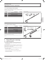
- Type
- Operation Instruction

INSTALLATION
BEFESTIGUNGSSYSTEM FÜR PFANNENDACH | FIXING SYSTEM FOR TILED ROOFS | SYSTÈME DE FIXATION POUR TOIT EN TUILES
» SOL BP
290788-36291-8664_SOL_BP_de_en_fr.indb 1 07.10.2011 14:39:20
Page is loading ...
Page is loading ...
Page is loading ...
Page is loading ...
Page is loading ...
Page is loading ...
Page is loading ...
Page is loading ...
Page is loading ...
Page is loading ...
Page is loading ...
Page is loading ...
Page is loading ...
Page is loading ...
Page is loading ...
Page is loading ...
Page is loading ...
Page is loading ...
Page is loading ...
Page is loading ...
Page is loading ...
Page is loading ...
Page is loading ...
Page is loading ...

CONTENTS
26 | SOL BP
1. General information ������������������������ 27
1.1 Safety information __________________________ 27
1.2 Other symbols in this documentation ___________ 27
1.3 Units of measurement _______________________ 27
1.4 Further applicable documents _________________ 27
2. Safety ������������������������������������ 27
2.1 Intended use _______________________________ 27
2.2 Safety information __________________________ 27
3. Product description ������������������������� 28
3.1 Standard delivery ___________________________ 28
4. Preparing for installation �������������������� 30
4.1 Selecting the position ________________________ 30
5. On end������������������������������������ 31
5.1 Materials __________________________________ 31
5.2 Overview of collector installation ______________ 31
5.3 Fitting roof hook ____________________________ 32
5.4 Installing the collector strip ___________________ 32
5.5 Installing prole rails _________________________ 32
5.6 Connecting up the mounting frames ___________ 33
5.7 Checking the screws _________________________ 33
5.8 Positioning the collectors _____________________ 33
5.9 Securing the collector ________________________ 33
6. Vertical with support ������������������������ 34
6.1 Materials __________________________________ 34
6.2 Installation overview _________________________ 34
6.3 Fitting roof hook ____________________________ 35
6.4 Vertical support _____________________________ 35
6.5 Installing prole rails _________________________ 36
6.6 Installing the collector strip ___________________ 37
6.7 Connecting up the mounting frames ___________ 37
6.8 Checking the screws _________________________ 37
6.9 Positioning the collectors _____________________ 37
6.10 Securing the collector ________________________ 37
7. Across next to each other �������������������� 38
7.1 Materials __________________________________ 38
7.2 Overview of collector installation ______________ 38
7.3 Fitting roof hook ____________________________ 39
7.4 Installing the collector strip ___________________ 39
7.5 Installing prole rails _________________________ 39
7.6 Connecting up the mounting frames ___________ 40
7.7 Checking the screws _________________________ 40
7.8 Positioning the collectors _____________________ 40
7.9 Securing the collector ________________________ 40
8. Side by side, across, with support ������������� 41
8.1 Materials __________________________________ 41
8.2 Installation overview _________________________ 41
8.3 Fitting roof hook ____________________________ 42
8.4 Vertical support _____________________________ 42
8.5 Installing the collector strip ___________________ 44
8.6 Connecting up the mounting frames ___________ 44
8.7 Checking the screws _________________________ 44
8.8 Positioning the collectors _____________________ 44
8.9 Securing the collector ________________________ 44
9. Across above each other ��������������������� 45
9.1 Materials __________________________________ 45
9.2 Installation overview _________________________ 45
9.3 Fitting roof hook ____________________________ 46
9.4 Fitting the lower pair of collector strips __________ 46
9.5 Installing prole rails _________________________ 46
9.6 Next collector row ___________________________ 47
9.7 Positioning the collectors _____________________ 47
9.8 Securing the lower collector __________________ 47
9.9 Lateral lock ________________________________ 48
10. Lightning protection ������������������������ 48
11. Warranty and environment ������������������ 48
290788-36291-8664_SOL_BP_de_en_fr.indb 26 07.10.2011 14:39:59

ENGLISH
INSTALLATION
GENERAL INFORMATION
SOL BP | 27
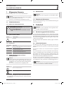
1. General information
These instructions are intended for contractors.
Note
Read these instructions carefully before using the ap-
pliance and retain them for future reference.
Pass on these instructions to the operator.
1.1 Safety information
1.1.1 Structure of safety information
KEYWORD Type of risk
Here, possible consequences are listed that may
result from non-observation of the safety infor-
mation.
f Steps to prevent the risk are listed.
1.1.2 Symbols, type of risk
Symbol Type of risk
!
Injury
1.1.3 Keywords
KEYWORD Description
DANGER If this information is not observed, it will result in serious
injury or death.
WARNING If this information is not observed, it can result in serious
injury or death.
CAUTION If this information is not observed, it can lead to me-
dium or minor injury.
1.2 Other symbols in this documentation
Note
Notes are bordered by horizontal lines above and
below the text. General information is marked with
the symbol shown on the left.
f Read these texts carefully.
Symbol
!
Damage to the appliance and environment
Appliance disposal
f This symbol indicates that you have to do something. The
action you need to take is described step by step.
1.3 Units of measurement
Note
All measurements are given in mm unless stated oth-
erwise.
1.4 Further applicable documents
Please observe the at-plate solar collectors operating and
installation instructions.
2. Safety
Note
Observe all applicable national and regional
regulations and instructions.
2.1 Intended use
This product is intended to be used for positioning and se-
curing at-plate solar collectors. Any other use beyond that
described shall be deemed inappropriate. Observation of these
instructions is also part of the correct use of this appliance.
Any changes or modications void any warranty.
2.2 Safety information
Installation, maintenance and repair must only be carried out
by a qualied contractor in accordance with these instructions.
Contractors are responsible for adherence to all applicable reg-
ulations during installation and commissioning. Accident pre-
vention regulations (e.g. VBG 74 in Germany) must be observed
when working with ladders, scaolding or lifting platforms!
!
WARNING Injury
Installation with these xing accessories is only per-
mitted up to a height of 20 metres.
290788-36291-8664_SOL_BP_de_en_fr.indb 27 07.10.2011 14:40:00

INSTALLATION
PRODUCT DESCRIPTION
28 | SOL BP
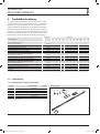
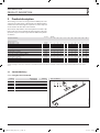
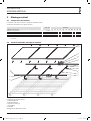
3. Product description
These xing accessories are designed to install at-plate solar
collectors on a tiled roof (e.g. “Breckland”). The following table
should assist when ordering. The required accessories depend
on the number of collectors to be installed.
The material composition is based on hydraulic assemblies. Up
to ve collectors can be hydraulically linked. From six collectors
upwards, arrays need to be separated into dierent hydraulic
assemblies.
Part no. Number
Flat-plate collector 1 2 3 4 5 6 8 10 12 15 16
Tiled roof, on end
Mounting frame SOL R1 230169 1 - 1 - 1 - - 2 - 3 -
Mounting frame SOL R2 230170 - 1 1 2 2 3 4 4 6 6 8
Frame connection kit SOL RV* 230171 - - 1 1 2 2 2 4 3 6 4
Fixing kit, tiled roof SOL BP 230175 2 2 3 4 5 6 8 10 12 15 16
Frame supports 15° to 30° SOL RA ◦ 230173 2 2 3 4 5 6 8 10 12 15 16
Tiled roofs, across, above each other
Mounting frame SOL R1 W 230920 1 2 3 4 5 6 8 10 12 15 16
Fixing kit, tiled roof SOL BP 230175 2 3 4 5 6 7 9 12 15 18 20
Frame connection kit, horizontal SOL RV-W 230172 - 1 2 3 4 4 6 8 9 12 16
Tiled roofs, across, side by side
Mounting frame SOL R1 W 230920 1 2 3 4 5 6 8 10 12 15 16
Frame connection kit SOL RV* 230171 - 1 2 3 4 4 6 8 9 12 12
Fixing kit, tiled roof SOL BP 230175 2 4 6 8 10 12 16 20 24 30 32
Frame supports 15° to 30° SOL RA ◦ 230173 2 4 6 8 10 12 16 20 24 30 32
◦
optional
* when intending to interconnect the frames of individual hydraulic assemblies, the number of frame connecting kits ordered must match this require-
ment.
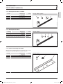
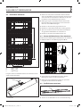
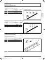
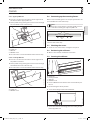
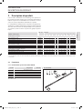
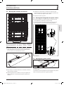
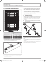
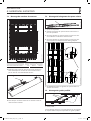
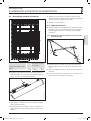
3.1 Standard delivery
3.1.1 Fixing kit, tiled roof SOL BP
Position Description Number Part no. 230175
1 Roof hooks 2
7
8
9
1
6
2
26_05_01_0201
2 Collector strip 1
6 Support plate 6
7 M10 nut 5
8 M10x20 screw 5
9 M10 washer 3
For each BP fixing kit, provide at least four wood screws (8/80) on site.
290788-36291-8664_SOL_BP_de_en_fr.indb 28 07.10.2011 14:40:01

ENGLISH
INSTALLATION
PRODUCT DESCRIPTION
SOL BP | 29
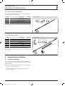
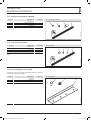
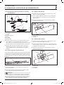
3.1.2 Mounting frame SOL R1 / SOL R1 W
Position Description Number Part no. 230169 / 230920
3 Profile rail 2
26_05_01_0183
8
7
5
3
5 Locking bracket 4
7 M10 nut 5
8 M10x20 screw 5
3.1.3 Mounting frame SOL R2
Position Description Number Part no. 230170
4 Profile rail 2
26_05_01_0532
5
7 8
4
5 Locking bracket 8
7 M10 nut 9
8 M10x20 screw 9
The SOL R2 mounting frame is designed for mounting a pair of collectors.
3.1.4 Frame connection kit SOL RV
Where several mounting frames are used, they should be con-
nected with frame connection kits.
Position Description Number Part no. 230171
7 M10 nut 9
26_05_01_0202
8 7 12
8 M10x20 screw 9
12 Frame connection strip 2
290788-36291-8664_SOL_BP_de_en_fr.indb 29 07.10.2011 14:40:02

INSTALLATION
PREPARING FOR INSTALLATION
30 | SOL BP
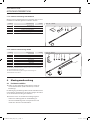
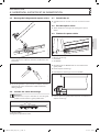
3.1.5 Frame connection kit SOL RV-W
Where several mounting frames are used, they should be con-
nected with frame connection kits.
Position Description Number Part no. 230172
2 Collector strip 1
26_05_01_0185
20
19
8
7
2
7 M10 nut 13
8 Screw M10 13
19 Double locking bracket 2
20 Joining bracket 2
3.1.6 Frame support SOL RA
Position Description Number Part no. 230173
7 M10 nut 3
26_05_01_0480
15 1716 18 8 7
14
13
8 Screw M10 3
13 Support angle strip 2
14 Brace 1
15 Pivoting bracket 4
16 Screw M6 16
17 M6 nut 16
18 M6 washer 16
You will only need the frame support if you intend changing the angle of
inclination of the collectors to create an optimum insolation angle.
The frame support RA enables the angle of inclination to be increased by
15° to 30°.
4. Preparing for installation
4.1 Selecting the position
The mounting frame for the collectors must not be tted at the
edge or in a corner of the roof. Observe the collector installa-
tion instructions.
f Observe the following when choosing the securing point
- existing air vent tiles and vents.
- the roof outlets for the hydraulic and electrical connec-
tions of the collectors.
290788-36291-8664_SOL_BP_de_en_fr.indb 30 07.10.2011 14:40:02

ENGLISH
INSTALLATION
ON END
SOL BP | 31
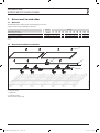
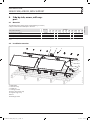
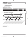
5. On end
5.1 Materials
The following table shows you the required xing accessories,
subject to the number of at-plate collectors.
Part no. Number
Flat-plate collector 1 2 3 4 5 6 8 10 12 15 16
Mounting frame SOL R1 230169 1 - 1 - 1 - - 2 - 3 -
Mounting frame SOL R2 230170 - 1 1 2 2 3 4 4 6 6 8
Frame connection kit SOL RV* 230171 - - 1 1 2 2 2 4 3 6 4
Fixing kit, tiled roof SOL BP 230175 2 2 3 4 5 6 8 10 12 15 16
* when intending to interconnect the frames of individual hydraulic assemblies, the number of frame connecting kits ordered must match this require-
ment.
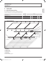
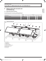
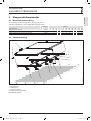
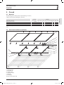
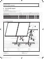
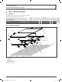
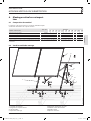
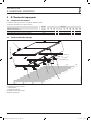
5.2 Overview of collector installation
82_05_01_0013
1
2
3
4
7
5
7
7
8
8
12
7
8
8
1 Roof hooks
2 Collector strip
3 R1 prole rail
4 Prole rail R2
5 Locking bracket
7 M10 nut
8 Screw M10
12 Frame connection strip
290788-36291-8664_SOL_BP_de_en_fr.indb 31 07.10.2011 14:40:04

INSTALLATION
ON END
32 | SOL BP
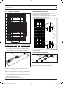
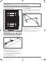
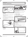
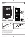
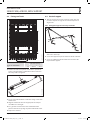
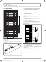
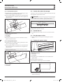
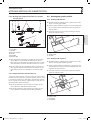
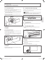
5.3 Fitting roof hook
A
B
26_05_01_0508
B A with R1 A with R2
Roof hook spacing mm 2080
-400
900
±200
1220
±200
f Remove the roof tiles up to the next rafter or push them
to one side. Note that the roof hooks must be located in
the valley of the corrugation.
26_05_01_0084
1
1 Roof hooks
f Secure each roof hook to the roof rafter using at least two
woodscrews.
f Align the roof hooks. Use the support plate to compen-
sate dierences in height.
f Tie a guide line between the outer roof hooks of the
planned collector array. Align any other roof hooks to this.
f Replace the roof tiles.
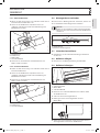
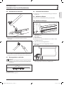
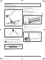
5.4 Installing the collector strip
f Secure the collector strip to the lower roof hook through
the second hole.
f Secure the collector strip to the upper roof hook through
a suitable slot.
26_05_01_0507
8
8 M10x20 screw
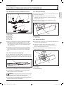
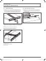
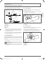
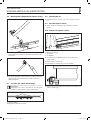
5.5 Installing prole rails
2
4
26_05_01_0484
2 Collector strip
4 Prole rail
The second and lowest hole in the collector strip are intended
for securing the prole rails.
290788-36291-8664_SOL_BP_de_en_fr.indb 32 07.10.2011 14:40:07

ENGLISH
INSTALLATION
ON END
SOL BP | 33
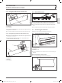
5.5.1 Upper prole rail
f Insert one screw on the left and one on the right side of
the channel of the upper prole rail.
f Fit the prole rail by pushing the inserted screws through
the second hole in the collector strip.
26_05_01_0579
2
4
8
7
2 Collector strip
4 Prole rail
7 M10 nut
8 M10x20 screw
f Fit a nut to the screw at the bottom of the collector strip.
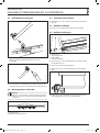
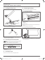
5.5.2 Lower prole rail
f Insert one screw on the left and one on the right side of
the prole rail channel.
f Fit the prole rail by pushing the inserted screws through
the bottom hole in the collector strip.
f Fit a nut to the screw at the bottom of the collector strip.
26_05_01_0486
4
2
8
2 Collector strip
4 Prole rail
8 M10x20 screw
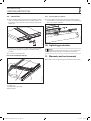
5.6 Connecting up the mounting frames
Where several mounting frames are used, they should be con-
nected with frame connection strips.
Note
Insert the screws into the side of the prole rail chan-
nel before installing the adjacent prole rail.
4
12
26_05_01_0488
4 Prole rails
12 Frame connection strip
5.7 Checking the screws
f Check all screw connections and tighten if required.
5.8 Positioning the collectors
f Observe the collector installation instructions.
5.9 Securing the collector
26_05_01_0620
5
7
4
8
4 Prole rail
5 Locking bracket
7 M10 nut
8 M10x20 screw
f Insert an M10x20 screw into the outer channel of the pro-
le rail.
f Fit the locking bracket in position.
f Secure the locking bracket with an M10 nut.
26_05_01_0533
f Secure the collector accordingly with one locking bracket
to the top prole rail.
290788-36291-8664_SOL_BP_de_en_fr.indb 33 07.10.2011 14:40:08

INSTALLATION
VERTICAL WITH SUPPORT
34 | SOL BP
6. Vertical with support
6.1 Materials
The following table shows you the required xing accessories,
subject to the number of at-plate collectors.
Part no. Number
Flat-plate collector
1 2 3 4 5 6 8 10 12 15 16
Mounting frame SOL R1 230169 1 - 1 - 1 - - 2 - 3 -
Mounting frame SOL R2 230170 - 1 1 2 2 3 4 4 6 6 8
Frame connection kit SOL RV* 230171 - - 1 1 2 2 2 4 3 6 4
Fixing kit, tiled roof SOL BP 230175 2 2 3 4 5 6 8 10 12 15 16
Frame support 15° to 30° SOL RA 230173 2 2 3 4 5 6 8 10 12 15 16
* When intending to interconnect the frames of individual hydraulic assemblies, the number of frame connecting kits ordered must match this require-
ment.
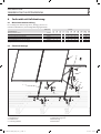
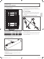
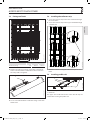
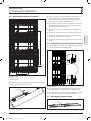
6.2 Installation overview
82_05_01_0007
5
15
13
4
15
13
1
14
2
1 Roof hooks
2 Collector strip
4 Prole rail
5 Locking bracket
12 Frame connection strip
13 Support angle strip
14 Brace
15 Pivoting bracket
290788-36291-8664_SOL_BP_de_en_fr.indb 34 07.10.2011 14:40:10

ENGLISH
INSTALLATION
VERTICAL WITH SUPPORT
SOL BP | 35
6.3 Fitting roof hook
A
B
26_05_01_0508
Roof hook spacing
Angle of inclination B A with R1 A with R2
15° mm 2080
-400
900
±200
1220
±200
22° mm 1995
-400
900
±200
1220
±200
30° mm 1864
-400
900
±200
1220
±200
f Remove the roof tiles up to the next rafter or push them
to one side. Note that the roof hooks must be located in
the valley of the corrugation.
26_05_01_0084
1
1 Roof hooks
f Secure each roof hook to the roof rafter using at least two
woodscrews.
f Align the roof hooks. Use the support plate to compen-
sate dierences in height.
f Tie a guide line between the outer roof hooks of the
planned collector array. Align any other roof hooks to this.
f Replace the roof tiles.
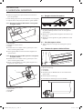
6.4 Vertical support
f Trim the support strips to the required length. You only
need one strip for an angle of 15°. Join two strips for an
angle of 30°.
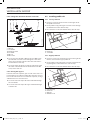
6.4.1 Fitting the support on the top roof hooks
26_05_01_0483
f Secure an L-bracket on the top roof hooks so that the
short side is at the top.
f Secure the support strip to the short side of this L-bracket.
f Secure an additional L-bracket with its short side to the
top end of the support.
290788-36291-8664_SOL_BP_de_en_fr.indb 35 07.10.2011 14:40:16

INSTALLATION
VERTICAL WITH SUPPORT
36 | SOL BP
6.4.2 Fitting the L-bracket to the lower roof hooks
26_05_01_0482
17
18 8
15
16
7
1
1 Roof hooks
7 M10 nut
8 Screw M10
15 Pivoting bracket
16 Screw M6
17 M6 nut
18 M6 washer
f Secure one L-bracket with a M10 screw and a M10 nut to
the roof hook. Insert the screw through the centre hole
on the long side of the L-bracket. The short side of the L-
bracket must be at the top.
f Secure the short side of the second L-bracket to the short
side of the L-bracket tted to the roof hook. Use the M6
screw, washer and nut.
6.4.3 Bracing the support
From two collectors upwards, you need to connect the cen-
tre eld with a brace. When installing four collectors or more,
brace both end elds. From six collectors upwards, arrange
additional braces in one inner eld.
f Secure the collector strip to the lower roof hook through
the second hole.
f Secure the collector strip to the upper roof hook through
a suitable slot.
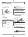
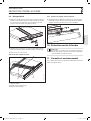
6.5 Installing prole rails
6.5.1 Lower prole rail
f Insert one screw on the left and one on the right side of
the prole rail channel.
f Fit the prole rail by pushing the inserted screws through
the bottom hole in the collector strip.
f Fit a nut to the screw at the bottom of the collector strip.
26_05_01_0486
4
2
8
2 Collector strip
4 Prole rail
8 Screw M10
6.5.2 Upper prole rail
f Insert one screw each on the left and one on the right side
into the channel of the upper prole rail.
f Fit the prole rail by pushing the inserted screws from the
top through the second hole in the collector strip.
f Fit a nut to the screw at the bottom of the collector strip.
26_05_01_0579
2
4
8
7
2 Collector strip
4 Prole rail
7 M10 nut
8 M10x20 screw
290788-36291-8664_SOL_BP_de_en_fr.indb 36 07.10.2011 14:40:17

ENGLISH
INSTALLATION
VERTICAL WITH SUPPORT
SOL BP | 37
6.6 Installing the collector strip
26_05_01_0196
f Secure the collector strip through the second hole with
the L-bracket on the lower roof hook.
26_05_01_0197
f Secure the collector strip through a suitable slot to the
upper L-bracket of the support.
6.7 Connecting up the mounting frames
Note
Insert the screws into the side of the prole rail chan-
nel before installing the adjacent prole rail.
4
12
26_05_01_0488
4 Prole rails
12 Frame connection strip
6.8 Checking the screws
f Check all screw connections and retighten a little, if
required.
6.9 Positioning the collectors
f Observe the collector installation instructions.
6.10 Securing the collector
26_05_01_0620
5
7
4
8
4 Prole rail
5 Locking bracket
7 M10 nut
8 M10x20 screw
f Insert an M10x20 screw into the outer channel of the pro-
le rail.
f Fit the locking bracket in position.
f Secure the locking bracket with an M10 nut.
26_05_01_0533
f Secure the collector accordingly with one locking bracket
to the top prole rail.
290788-36291-8664_SOL_BP_de_en_fr.indb 37 07.10.2011 14:40:18

INSTALLATION
ACROSS NEXT TO EACH OTHER
38 | SOL BP
7. Across next to each other
7.1 Materials
The following table shows you the required xing accessories,
subject to the number of at-plate collectors.
Part no. Number
Flat-plate collector 1 2 3 4 5 6 8 10 12 15 16
Mounting frame SOL R1 W 230920 1 2 3 4 5 6 8 10 12 15 16
Frame connection kit SOL RV* 230171 - 1 2 3 4 4 6 8 9 12 12
Fixing kit, tiled roof SOL BP 230175 2 4 6 8 10 12 16 20 24 30 32
* When intending to interconnect the frames of individual hydraulic assemblies, the number of frame connecting kits ordered must match this require-
ment.
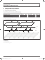
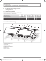
7.2 Overview of collector installation
82_05_01_0012
5
12
1
3
2
1 Roof hooks
2 Collector strip
3 Prole rail
5 Locking bracket
12 Frame connection strip
290788-36291-8664_SOL_BP_de_en_fr.indb 38 07.10.2011 14:40:22

ENGLISH
INSTALLATION
ACROSS NEXT TO EACH OTHER
SOL BP | 39
7.3 Fitting roof hook
A
B
26_05_01_0508
A B
Roof hook spacing mm 1220
±200
1076
-400
f Remove the roof tiles up to the next rafter or push them
to one side. Note that the roof hooks must be located in
the valley of the corrugation.
26_05_01_0084
1
1 Roof hooks
f Secure each roof hook to the roof rafter using at least two
woodscrews.
7.4 Installing the collector strip
f Secure the collector strip to the lower roof hook through
the second hole.
f Secure the collector strip to the upper roof hook through
a suitable slot.
26_05_01_0518
8
8 M10x20 screw for securing the collector strip to the roof
hook
7.5 Installing prole rails
2
3
26_05_01_0484
2 Collector strip
3 Prole rail
The upper slot and the lowest hole in the collector strip are
intended for securing the prole rails.
290788-36291-8664_SOL_BP_de_en_fr.indb 39 07.10.2011 14:40:23

INSTALLATION
ACROSS NEXT TO EACH OTHER
40 | SOL BP
7.5.1 Upper prole rail
f Insert one screw on the left and one on the right side of
the channel of the upper prole rail.
f Fit the prole rail by pushing the inserted screws through
the highest slot in the collector strip.
f Fit a nut to the screw at the bottom of the collector strip.
26_05_01_0579
2
3
8
7
2 Collector strip
3 Prole rail
7 M10 nut
8 M10x20 screw
7.5.2 Lower prole rail
f Insert one screw on the left and one on the right side of
the prole rail channel.
f Fit the prole rail by pushing the inserted screws through
the bottom hole in the collector strip.
26_05_01_0486
3
2
8
2 Collector strip
3 Prole rail
8 M10x20 screw
f Fit a nut to the screw at the bottom of the collector strip.
7.6 Connecting up the mounting frames
Where several mounting frames are used, they should be con-
nected with frame connection strips.
Note
Insert the screws into the side of the prole rail chan-
nel before installing the adjacent prole rail.
3
12
26_05_01_0488
3 Prole rails
12 Frame connection strip
7.7 Checking the screws
f Check all screw connections and tighten if required.
7.8 Positioning the collectors
f Observe the collector installation instructions.
7.9 Securing the collector
26_05_01_0620
5
7
3
8
3 Prole rail
5 Locking bracket
7 M10 nut
8 M10x20 screw
f Insert an M10x20 screw into the outer channel of the pro-
le rail.
f Fit the locking bracket in position.
f Secure the locking bracket with an M10 nut.
26_05_01_0533
f Secure the collector accordingly with one locking bracket
to the top prole rail.
290788-36291-8664_SOL_BP_de_en_fr.indb 40 07.10.2011 14:40:24

ENGLISH
INSTALLATION
SIDE BY SIDE, ACROSS, WITH SUPPORT
SOL BP | 41
8. Side by side, across, with sup-
port
8.1 Materials
The following table shows you the required xing accessories,
subject to the number of at-plate collectors.
Part no. Number
Flat-plate collector 1 2 3 4 5 6 8 10 12 15 16
Mounting frame SOL R1 W 230920 1 2 3 4 5 6 8 10 12 15 16
Frame connection kit SOL RV* 230171 - 1 2 3 4 4 6 8 9 12 12
Fixing kit, tiled roof SOL BP 230175 2 4 6 8 10 12 16 20 24 30 32
Frame supports 15° to 30° SOL RA 230173 2 4 6 8 10 12 16 20 24 30 32
* When intending to interconnect the frames of individual hydraulic assemblies, the number of frame connecting kits ordered must match this require-
ment.
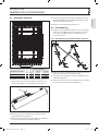
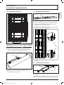
8.2 Installation overview
82_05_01_0008
12
3
5
15
13
14
1
2
1 Roof hooks
2 Collector strip
3 Prole rail
5 Locking bracket
12 Frame connection strip
13 Support angle strip
14 Brace
15 Pivoting bracket
290788-36291-8664_SOL_BP_de_en_fr.indb 41 07.10.2011 14:40:27

INSTALLATION
SIDE BY SIDE, ACROSS, WITH SUPPORT
42 | SOL BP
8.3 Fitting roof hook
A
B
26_05_01_0508
Roof hook spacing
Angle of inclination A B
30° mm 1220
±200
859
-400
f Remove the roof tiles up to the next rafter or push them
to one side. Note that the roof hooks must be located in
the valley of the corrugation.
26_05_01_0084
1
1 Roof hooks
f Secure each roof hook to the roof rafter using at least two
woodscrews.
f Align the roof hooks. Use the support plate to compen-
sate dierences in height.
f Tie a guide line between the outer roof hooks of the
planned collector array. Align any other roof hooks to this.
f Replace the roof tiles.
8.4 Vertical support
f Trim the support strips to the required length. You only
need one strip for an angle of 15°. Join two strips for an
angle of 30°.
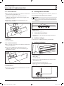
8.4.1 Fitting the support on the top roof hooks
26_05_01_0635
f Secure an L-bracket on the top roof hooks so that the
short side is at the top.
f Secure the support strip to the short side of this L-bracket.
f Secure an additional L-bracket with its short side to the
top end of the support.
290788-36291-8664_SOL_BP_de_en_fr.indb 42 07.10.2011 14:40:28

ENGLISH
INSTALLATION
SIDE BY SIDE, ACROSS, WITH SUPPORT
SOL BP | 43
8.4.2 Fitting the L-bracket to the lower roof hooks
26_05_01_0482
17
18 8
15
16
7
1
1 Roof hooks
7 M10 nut
8 Screw M10
15 Pivoting bracket
16 Screw M6
17 M6 nut
18 M6 washer
f Secure one L-bracket with a M10 screw and a M10 nut to
the roof hook. Insert the screw through the centre hole
on the long side of the L-bracket. The short side of the L-
bracket must be at the top.
f Secure the short side of the second L-bracket to the short
side of the L-bracket tted to the roof hook. Use the M6
screw, washer and nut.
8.4.3 Bracing the support
When installing two collectors or more, brace the centre eld.
When installing four collectors or more, brace both end elds.
From six collectors upwards, arrange additional braces in one
inner eld.
f Secure the collector strip to the lower roof hook through
the second hole.
After tting one support, t the collector strip to
the L-brackets.
f Secure the collector strip to the upper roof hook through
a suitable slot.
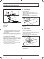
8.4.4 Lower prole rail
f Insert one screw on the left and one on the right side of
the prole rail channel.
f Fit the prole rail by pushing the inserted screws through
the bottom hole in the collector strip.
f Fit a nut to the screw at the bottom of the collector strip.
26_05_01_0486
3
2
8
2 Collector strip
3 Prole rail
8 Screw M10
8.4.5 Upper prole rail
f Insert one screw each on the left and one on the right side
into the channel of the upper prole rail.
f Fit the prole rail by pushing the inserted screws from the
top through the highest slot in the collector strip.
f Fit a nut to the screw at the bottom of the collector strip.
26_05_01_0579
2
3
8
7
2 Collector strip
3 Prole rail
7 M10 nut
8 M10x20 screw
290788-36291-8664_SOL_BP_de_en_fr.indb 43 07.10.2011 14:40:30

INSTALLATION
SIDE BY SIDE, ACROSS, WITH SUPPORT
44 | SOL BP
8.5 Installing the collector strip
26_05_01_0196
f Secure the collector strip through the second hole with
the L-bracket on the lower roof hook.
26_05_01_0197
f Secure the collector strip through a suitable slot to the
upper L-bracket of the support.
8.6 Connecting up the mounting frames
Note
Insert the screws into the side of the prole rail chan-
nel before installing the adjacent prole rail.
3
12
26_05_01_0488
3 Prole rails
12 Frame connection strip
8.7 Checking the screws
f Check all screw connections and retighten a little.
8.8 Positioning the collectors
f Observe the collector installation instructions.
8.9 Securing the collector
26_05_01_0620
5
7
3
8
3 Prole rail
5 Locking bracket
7 M10 nut
8 M10x20 screw
f Insert an M10x20 screw into the outer channel of the pro-
le rail.
f Fit the locking bracket in position.
f Secure the locking bracket with an M10 nut.
26_05_01_0533
f Secure the collector accordingly with one locking bracket
to the top prole rail.
290788-36291-8664_SOL_BP_de_en_fr.indb 44 07.10.2011 14:40:30
Page is loading ...
Page is loading ...
Page is loading ...
Page is loading ...
Page is loading ...
Page is loading ...
Page is loading ...
Page is loading ...
Page is loading ...
Page is loading ...
Page is loading ...
Page is loading ...
Page is loading ...
Page is loading ...
Page is loading ...
Page is loading ...
Page is loading ...
Page is loading ...
Page is loading ...
Page is loading ...
Page is loading ...
Page is loading ...
Page is loading ...
Page is loading ...
Page is loading ...
Page is loading ...
Page is loading ...
Page is loading ...
-
 1
1
-
 2
2
-
 3
3
-
 4
4
-
 5
5
-
 6
6
-
 7
7
-
 8
8
-
 9
9
-
 10
10
-
 11
11
-
 12
12
-
 13
13
-
 14
14
-
 15
15
-
 16
16
-
 17
17
-
 18
18
-
 19
19
-
 20
20
-
 21
21
-
 22
22
-
 23
23
-
 24
24
-
 25
25
-
 26
26
-
 27
27
-
 28
28
-
 29
29
-
 30
30
-
 31
31
-
 32
32
-
 33
33
-
 34
34
-
 35
35
-
 36
36
-
 37
37
-
 38
38
-
 39
39
-
 40
40
-
 41
41
-
 42
42
-
 43
43
-
 44
44
-
 45
45
-
 46
46
-
 47
47
-
 48
48
-
 49
49
-
 50
50
-
 51
51
-
 52
52
-
 53
53
-
 54
54
-
 55
55
-
 56
56
-
 57
57
-
 58
58
-
 59
59
-
 60
60
-
 61
61
-
 62
62
-
 63
63
-
 64
64
-
 65
65
-
 66
66
-
 67
67
-
 68
68
-
 69
69
-
 70
70
-
 71
71
-
 72
72


STIEBEL ELTRON SOL BP Operation Instruction
- Type
- Operation Instruction
Ask a question and I''ll find the answer in the document
Finding information in a document is now easier with AI
in other languages
- français: STIEBEL ELTRON SOL BP
- Deutsch: STIEBEL ELTRON SOL BP
Related papers
Other documents
-
Projecta Solo 8000 Specification
-
Buderus SKR6.1R Installation And Maintenance Instructions Manual
-
IFM E21002 Installation guide
-
-
State Water Heaters Corrugated Metal Roof User manual
-
-
-
Wolf CFK-1 Installation, Operating And Maintenance Instructions
-
-
Smartpool Sunheater S425 Installation & Operation Manual