Product information
Separating and protective instruments
Overvoltage arresters
B53-19
B61-300, B61-300 FI
B62-36G, B62-30W
B63-32, B63-48
B81-35
Document ID: 50707
2
Contents
Separating and protective instruments
50707-EN-170321
Contents
1 Product description ............................................................................................................................................................................................... 3
2 Type overview ......................................................................................................................................................................................................... 4
3 Electrical connection ............................................................................................................................................................................................. 5
4 Dimensions ............................................................................................................................................................................................................. 7
Take note of safety instructions for Ex applications
Please note the Ex specic safety information which you can nd on our homepage www.vega.com/downloads under "Approvals" and which
comes with every instrument. In hazardous areas you should take note of the corresponding regulations, conformity and type approval certi-
cates of the sensors and power supply units. The sensors must only be operated on intrinsically safe circuits. The permissible electrical values
are stated in the certicate.
3
Product description
Separating and protective instruments
50707-EN-170321
1 Product description
Overvoltage arresters limit interference and overvoltages in industrial
system to uncritical values so that failures and malfunctions of connected
instruments cannot occur.
An overvoltage arrester can be used on both sides of the circuit. It is e.g.
mounted on a carrier rail near the sensor, directly in the cable entry, or
near the signal conditioning instrument, PLC or control system. This way,
the eld side as well as the processing side are protected in case of volt-
age surges.
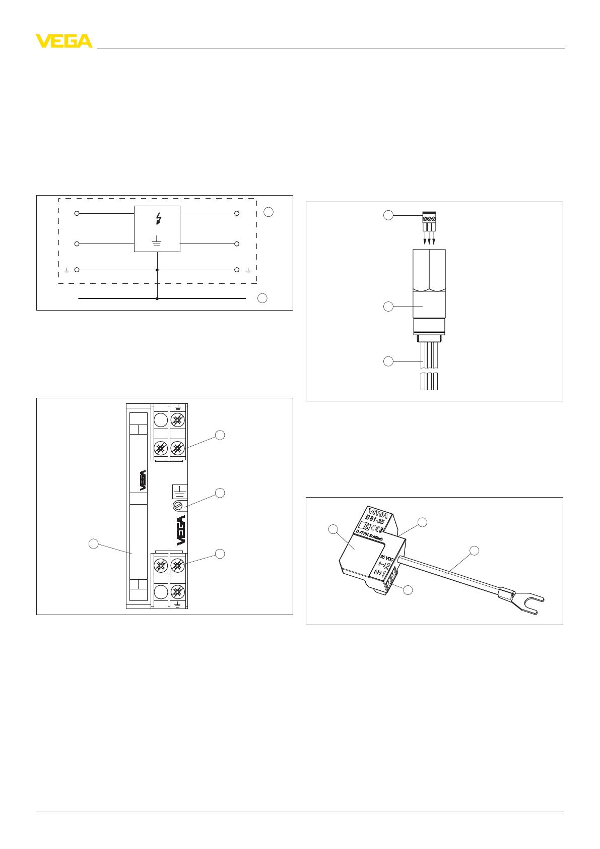
The following circuit diagram shows the electrical conguration of an
overvoltage arrester.
1
E1
E2
A1
A2
2
Fig. 1: Simplied circuit diagram with an overvoltage arrester, in this case a B62-
36G
1 Overvoltage arrester
2 Potential equalisation
This product information booklet gives you an overview and helps you
select the right overvoltage arrester.
Overvoltage arrester for carrier rail mounting
Ty p B62 - 36 G
OUT
IN
IP 20
max. 36 V DC/ li = 450 A
Li <= 0,15 mH / Ci <= 2,5 nF
E1
E2
A1
A2
A1+
A2-
E1+
E2-
4
1
2
3
Fig. 2: Conguration of an overvoltage arrester for carrier rail mounting, in this case
a B62-36G
1 Terminals "Out" (protected side)
2 Screw for carrier rail fastening
3 Terminals "In" (unprotected side)
4 Type label
Overvoltage arrester B53-19
The B53-19 is an overvoltage arrester for the measuring cable of conduc-
tive probes.
Overvoltage arrester B61-300
The B61-300 is an overvoltage arrester for sensors and signal condition-
ing instruments with mains voltage supply.
Overvoltage arrester B61-300 FI
The B61-300 FI is an overvoltage arrester for sensors and signal con-
ditioning instruments with mains power supply connected via a fault-
current circuit breaker (FI).
Overvoltage arrester B62-30W
The B62-30W is an overvoltage arrester for supply and control cables for
Probus PA instruments.
Overvoltage arrester B62-36G
The B62-36G is an overvoltage arrester for sensors and signal condition-
ing instruments in two-wire technology 4 … 20 mA/HART.
Overvoltage arrester for mounting in sensor housing
1
2
3
Fig. 3: Conguration of an overvoltage arrester for mounting inside the sensor
housing
1 Terminals for the signal cable input (unprotected side)
2 Overvoltage protection
3 Signal cable output to the sensor (protected side)
Overvoltage arrester B63-32, B63-48
B63-32 and B63-48 are overvoltage arresters for installation inside the
housings of VEGA level and pressure sensors.
1
2
3
4
Fig. 4: Conguration, overvoltage arrester for mounting on the sensor electronics
1 Overvoltage protection
2 Plug connector to the sensor electronics (protected side)
3 Connection cable to ground terminal
4 Terminal block to the supply and signal cable (unprotected side)
Overvoltage arrester B81-35
The B81-35 is an overvoltage arrester for mounting on the electronics
modules of VEGA level and pressure sensors.
4
Type overview
Separating and protective instruments
50707-EN-170321
2 Type overview
B53-19 B61-300 B61-300FI B62-30W B62-36G
Area of application Measuring cable of con-
ductive probes
Sensors and signal con-
ditioning instruments
with mains voltage sup-
ply
Sensors and signal con-
ditioning instruments
with mains voltage sup-
ply through fault-current
circuit breaker (FI)
Supply and signal ca-
bles of Probus PA
instruments
Sensors and signal con-
ditioning instruments
in two-wire technology
4 … 20 mA/HART
Operating voltage 19 V 100 … 300 V AC/DC 100 … 300 V AC/DC 9 … 36 V DC 9 … 36 V DC
Response voltage 22 V 500 V 500 V 41 V 41 V
Mounting Carrier rail mounting
Ambient temperature -40 … +60 °C (-40 … +140 °F)
Protection rating IP 20 (unmounted), IP 65 (mounted)
Approvals - ATEX, IEC
B63-32/48 B81-35
Area of application Sensors in two-wire technology 4 … 20 mA/HART, Probus PA,
Foundation Fieldbus
Sensors in two-wire technology 4 … 20 mA/HART, Probus PA,
Foundation Fieldbus
Operating voltage 32 V DC/48 V DC 9 … 35 V DC
Response voltage 38 V/76 V 41 V
Mounting In the sensor housing On the sensor electronics
Ambient temperature -40 … +85 °C (-40 … +185 °F) -40 … +85 °C (-40 … +176 °F)
Protection rating IP 20 (unassembled)
IP 66/IP 67, IP 66/IP 68 (0.2 bar) - mounted
Approvals ATEX
5
Electrical connection
Separating and protective instruments
50707-EN-170321
3 Electrical connection
3.1 Connection B53-19
Wiring plan
1
2
3
4
5
Typ B53 - 19
OUT
IN
IP 20
max. 19 VAC, 27 VDC/1 A
Li <= 0,5 mH / Ci <= 3nF
A1 A2
E1
E2
A3
E3
0
10
8
7
6
5
4
N
L1
3
2
1
max.
min.
1
2
N
L1
E1
E2
A1
A2
Fig. 12: Wiring plan, overvoltage arrester B53-19 with conductive single rod probe
1 Measuring probe
2 Overvoltage protection
3 Protected instrument (signal conditioning instrument)
4 Voltage supply
5 Potential equalisation
3.2 Connection B61-300
Wiring plan
B61 - 300
OUT
IN
IP 20
max. 300 V AC/0,5 A
L1
N
L1
N
2
3
6
5
4
1
L1
N
PE
Fig. 13: Wiring plan, overvoltage arrester B61-300
1 Mains supply
2 Overvoltage protection
3 PE terminal
4 Protected instrument (e.g. signal conditioning instrument)
5 Carrier rail
6 Potential equalisation
3.3 Connection B61-300 FI
Wiring plan
B61 - 300 FI
OUT
IN
IP 20
max. 300 V AC/0,5 A
L1
N
L1
N
2
3
5
4
1
L1
N
PE
Fig. 14: Wiring plan, overvoltage arrester B61-300 FI
1 Mains supply through fault-current circuit breaker (FI)
2 Overvoltage protection
3 PE terminal
4 Protected instrument (e.g. signal conditioning instrument)
5 Carrier rail
3.4 Connection B62-30W
Wiring plan
+
-
1+
2 -
B62 - 30 W
OUT
IN
IP 20
max. 36 VDC/ li 0,4 A
Ri = 3,6 Ohm
E1
E2
A1
A2
A1+
A2-
E1+
E2-
4
3
2
1
Fig. 15: Wiring plan, overvoltage arrester B62-30W
1 Protected instrument (sensor)
2 Overvoltage protection
3 Probus PA System
4 Potential equalisation
6
Electrical connection
Separating and protective instruments
50707-EN-170321
3.5 Connection B62-36G
Wiring plan
1+
2 -
+
+
-
3
2
1
Typ B62 - 36 G
OUT
IN
IP 20
max. 36 V DC/ li = 450 A
Li <= 0,15 mH / Ci <= 2,5 nF
E1
E2
A1
A2
A1+
A2-
E1+
E2-
Fig. 16: Wiring plan, overvoltage arrester B62-36G
1 Protected instrument (sensor)
2 Overvoltage protection
3 Signal conditioning instrument/PLC
4 Potential equalisation
3.6 Connection B63-32, B63-48
Wiring plan
4
3
2
1
5
1
2
+
( )
(-)
678
4...20mA
-
E
+
+
-
Fig. 17: Wiring plan, overvoltage arrester B63-32, B63-48
1 Protected instrument (sensor)
2 Overvoltage arrester
3 Signal conditioning instrument/PLC
4 Potential equalisation
Terminals sensor Wire colour/Polarity
1 Red (+)
2 Black (-)
Ground terminal Green/Yellow
3.7 Connection B81-35
Wiring plan
5
B81-35
CE
0044
35 VDC
D-77761 Schiltach
1
2
+
( )
(-)
678
4...20mA
1
3
2
Fig. 18: Wiring plan, overvoltage arrester B81-35
1 Voltage supply/Signal output
2 Overvoltage protection
3 Ground terminal for connection of the cable screenand the connection cable of
the overvoltage protection module
7
Dimensions
Separating and protective instruments
50707-EN-170321
4 Dimensions
Overvoltage arrester for carrier rail mounting
84 mm
(3.31")
52 mm
(2.05")
25 mm
(0.98")
Fig. 19: Dimensions, overvoltage protection
Housing
ø5,5 mm
(0.22")
86 mm
(3.39")
120 mm
(4.72")
160 mm
(6.30")
77 mm
(3.03")
47 mm
(1.85")
50 mm
(1.97")
ø4,5 mm
(0.18")
82 mm
(3.23")
68 mm
(2.68")
72 mm
(2.84")
130 mm
(5.12")
116 mm
(4.57")
M 20 x 1,5
M 20 x 1,5
1
2
Fig. 20: Dimensions, housing
1 Plastic housing
2 Aluminium housing
Overvoltage arrester for mounting in sensor housing
76 mm
(2.99")
SW 27 mm
(1.06")
56 mm
(2.21")
300 mm
(11.81")
8 mm
(0.31")
76 mm
(2.99")
56 mm
(2.21")
300 mm
(11.81")
1
2
E
-
+
Fig. 21: Dimensions, overvoltage protection
1 Thread M20 x 1.5 or ½ NPT, depending on order specication
Overvoltage arrester for mounting on sensor electronics
17 mm
(0.67")
9 mm
(0.35")
10 mm
(0.39")
19 mm
(0.75")
74 mm
(2.91")
27 mm
(1.08")
12 mm
(0.47")
Fig. 22: Dimensions, overvoltage protection
VEGA Grieshaber KG
Am Hohenstein 113
77761 Schiltach
Germany
50707-EN-170321
All statements concerning scope of delivery, application, practical use and operating conditions of the sensors and processing systems correspond to the information
available at the time of printing.
Subject to change without prior notice
© VEGA Grieshaber KG, Schiltach/Germany 2017
Phone +49 7836 50-0
Fax +49 7836 50-201
www.vega.com
  • Page 1 1
  • Page 2 2
  • Page 3 3
  • Page 4 4
  • Page 5 5
  • Page 6 6
  • Page 7 7
  • Page 8 8

Ask a question and I''ll find the answer in the document

Finding information in a document is now easier with AI