Page is loading ...

Supplementary instructions
Overvoltage protection mod-
ule
B81-35
Document ID: 50708

2
Contents
Overvoltage protection module • B81-35
50708-EN-170209
Contents
1 For your safety
1.1 Appropriate use ................................................................................................................ 3
1.2 General safety instructions ............................................................................................... 3
2 Product description
3 Connecting and mounting
3.1 Connecting ....................................................................................................................... 5
3.2 Wiring plan ....................................................................................................................... 7
4 Supplement
4.1 Technical data .................................................................................................................. 8
4.2 Dimensions ...................................................................................................................... 9
Safety instructions for Ex areas
Please note the Ex-specic safety information for installation and op-
eration in Ex areas. These safety instructions are part of the operating
instructions manual and come with the Ex-approved instruments.
Editing status: 2017-02-08

3
1 For your safety
Overvoltage protection module • B81-35
50708-EN-170209
1 For your safety
1.1 Appropriate use
The overvoltage protection module B81-35 is an accessory part for
existing plics
®
sensors.
1.2 General safety instructions
The safety information in the operating instructions manual of the
respective sensor must be noted.

4
2 Product description
Overvoltage protection module • B81-35
50708-EN-170209
2 Product description
The scope of delivery encompasses:
•
Overvoltage protection module B81-35
•
Screwdriver 2 mm
•
Documentation
– This supplementary instructions manual
The overvoltage protection module B81-35 is an accessory part the
following instruments in two-wire technology with detachable terminal
block.
•
VEGAPULS series 60 from hardware ≥ 2.0.0, software ≥ 4.0.0
•
VEGAPULS 64, 69
•
VEGAFLEX 80 series
•
VEGABAR series 80
•
VEGADIS 82
It is suitable for the following signal outputs:
•
4 … 20 mA
•
4 … 20 mA/HART, 4 … 20 mA/HART SIL
•
Probus PA, Foundation Fieldbus
The module is used instead of the terminals in the single or double
chamber housing.
It consists of a terminal block for the supply and signal cable, a plug
connector for the terminals of the sensor electronics and a connection
cable for connection to the ground terminal.
The overvoltage protection module B81-35 reduces any voltage
surges that may reach the signal cables to a harmless level. It con-
tains as voltage-limiting components a gas conductor for bleeding o
impulses of up to 10 kA to ground.
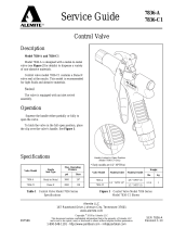
1
2
3
4
Fig. 1: Conguration, overvoltage protection module B81-35
1 Module housing
2 Plug connector for terminals of the sensor electronics (bottom side)
3 Connection cable for connection to the ground terminal
4 Terminal block for supply and signal cable
Scope of delivery
Application area

5
3 Connecting and mounting
Overvoltage protection module • B81-35
50708-EN-170209
3 Connecting and mounting
3.1 Connecting
The connection to voltage supply and the signal output is carried out
via screw terminals, the connection to the sensor electronics through
contact pins in the module housing. The connection to the ground
terminal is carried out via a connection cable with cable lug.
Information:
The overvoltage protection module is pluggable and can be removed
from the sensor electronics. To do this, lift the overvoltage protection
module with a small screwdriver and pull it out.
Proceed as follows:
1. Unscrew the housing lid
2. If a display and adjustment module is installed, remove it by turn-
ing it slightly to the left.
3. Lift the terminal block from the sensor electronics with a screw-
driver and pull it o
4. Loosen compression nut of the cable entry gland
5. Remove approx. 10 cm (4 in) of the cable mantle, strip approx.
1 cm (0.4 in) of insulation from the ends of the individual wires
6. Insert the cable into the sensor through the cable entry
7. Connect the wire ends according to the wiring diagram to the
screw termins. You can nd the max. wire cross-section under
"Technical data"
8. Check the hold of the wires in the terminals by lightly pulling on
them
9. Connect the connection cable of the overvoltage protection mod-
ule to the internal ground terminal, connect the external ground
terminal to potential equalisation
10. Plug the overvoltage protection module onto the sensor electron-
ics
Connection technology
Connection procedure

6
3 Connecting and mounting
Overvoltage protection module • B81-35
50708-EN-170209
Fig. 2: Plug the overvoltage protection module onto the sensor electronics -
single chamber housing
Fig. 3: Plug the overvoltage protection module onto the sensor electronics -
double chamber housing
11. Tighten the compression nut of the cable entry gland. The seal
ring must completely encircle the cable
12. Reinsert the display and adjustment module, if one was installed
13. Screw the housing lid back on
The electrical connection is nished.
Disassembly is carried out in reverse order.

7
3 Connecting and mounting
Overvoltage protection module • B81-35
50708-EN-170209
3.2 Wiring plan
5
B81-35
CE
0044
35 VDC
D-77761 Schiltach
1
2
+
( )
(-)
678
4...20mA
1
3
2
Fig. 4: Electronics and terminal compartment, single chamber housing, terminal
compartment, double chamber housing
1 Voltage supply/Signal output
2 Overvoltage protection module
3 Ground terminal for connection of the cable screenand the connection cable
of the overvoltage protection module
Electronics and terminal
compartment

8
4 Supplement
Overvoltage protection module • B81-35
50708-EN-170209
4 Supplement
4.1 Technical data
Note for approved instruments
The technical data in the respective safety instructions are valid for approved instruments (e.g. with
Ex approval). These data can dier from the data listed herein, for example regarding the process
conditions or the voltage supply.
General data
Version Module for inserting into the sensor electronics
Housing material PA
Ambient conditions
Ambient, storage and transport tempera-
ture
-40 … +80 °C (-40 … +176 °F)
Electrical characteristics
Highest continuous operating voltage
35 V DC
Max. permissible input current 500 mA
Response voltage > 500 V
Discharge current < 10 kA (8/20 µs)
Category according to DIN EN 61643-21 C1 (2 kV/1 kA)
Overload failure mode 1
signal transmission
4 … 20 mA, 4 … 20 mA/HART, eldbus
Electromechanical data
Wire cross-section, screw terminals
Ʋ Massive wire 1.5
2
mm
Ʋ Stranded wire with end sleeve 0.5
2
mm
Electrical protective measures
Protection rating
Ʋ unassembled IP 20
Ʋ Mounted into the sensor housing according to housing protection

9
4 Supplement
Overvoltage protection module • B81-35
50708-EN-170209
4.2 Dimensions
17 mm
(0.67")
9 mm
(0.35")
10 mm
(0.39")
19 mm
(0.75")
74 mm
(2.91")
27 mm
(1.08")
12 mm
(0.47")
Fig. 5: Dimensions, overvoltage protection module B81-35

10
Notes
Overvoltage protection module • B81-35
50708-EN-170209

11
Notes
Overvoltage protection module • B81-35
50708-EN-170209

Printing date:
VEGA Grieshaber KG
Am Hohenstein 113
77761 Schiltach
Germany
50708-EN-170209
All statements concerning scope of delivery, application, practical use and operat-
ing conditions of the sensors and processing systems correspond to the information
available at the time of printing.
Subject to change without prior notice
© VEGA Grieshaber KG, Schiltach/Germany 2017
Phone +49 7836 50-0
Fax +49 7836 50-201
E-mail: [email protected]
www.vega.com
/