Page is loading ...

Dual 600A BDFB / BDCBB
Model 007-0001-2600
User Manual 122645-5 A0

Telect, Inc. • USA +1.509.926.6000 • Mexico +1.52.33.3836.3700
Poland +1.48.713.239.100 • UK +1.44.1489.889500 • www.telect.com
Copyright © 2002 Telect, Inc., All Rights Reserved
ii

Telect, Inc. • USA +1.509.926.6000 • Mexico +1.52.33.3836.3700
Poland +1.48.713.239.100 • UK +1.44.1489.889500 • www.telect.com
Copyright © 2002 Telect, Inc., All Rights Reserved • Telect Publication 122645-5 A0
Contents
1 Descriptions
Dual 600A BDFB / BDCBB ............................................................................................................................ 1-1
Capabilities .............................................................................................................................................. 1-1
Features................................................................................................................................................... 1-1
Specifications................................................................................................................................................. 1-3
2 Installation
Installation Considerations............................................................................................................................. 2-1
Tools and Equipment............................................................................................................................... 2-1
Technical Support.................................................................................................................................... 2-1
Inspection....................................................................................................................................................... 2-1
Bay Layout ..................................................................................................................................................... 2-1
Panel Installation............................................................................................................................................ 2-2
Cable Installation............................................................................................................................................ 2-4
A. Install Ground Cabling......................................................................................................................... 2-5
B. Install Input Cabling............................................................................................................................. 2-6
C. Install Intrabay & Interbay Cabling ...................................................................................................... 2-8
D. Install Alarm Cabling ........................................................................................................................... 2-8
E. Test Inputs & Alarms Without Breakers .............................................................................................. 2-9
F. Install Output Cabling ........................................................................................................................ 2-10
Circuit Breaker Installation ........................................................................................................................... 2-11
3 Output Testing
4 Service
Owner Maintenance....................................................................................................................................... 4-1
In Case Of Difficulty........................................................................................................................................ 4-1
In-Warranty Service........................................................................................................................................ 4-1
Out-Of-Warranty Service................................................................................................................................ 4-1
Repacking For Shipment................................................................................................................................ 4-2
5 Accessories

Telect, Inc. • USA +1.509.926.6000 • Mexico +1.52.33.3836.3700
Poland +1.48.713.239.100 • UK +1.44.1489.889500 • www.telect.com
Copyright © 2002 Telect, Inc., All Rights Reserved
Page iv

Telect, Inc. • USA +1.509.926.6000 • Mexico +1.52.33.3836.3700
Poland +1.48.713.239.100 • UK +1.44.1489.889500 • www.telect.com
Copyright © 2002 Telect, Inc., All Rights Reserved • Telect Publication 122645-5 A0
1. Description
DUAL 600A BDFB / BDCBB
Telect’s Dual 600A Battery Distribution Fuse Board / Circuit
Breaker Board (BDFB / BDCBB), Model 007-0001-2600, contains
two non-shared sets of input buses. Both sets of -48VDC/RTN in-
put buses are capable of 600A primary distribution feed to 18 cir-
cuit breaker output positions.
The open-frame architecture of the BDFB / BDCBB allows unre-
stricted top-down or bottom-up cabling of inputs and outputs.
The front panel contains 18 circuit breaker positions per feed for a
total of 36 per panel. Each position accepts a standard “bullet ter-
minal” circuit breaker rated up to 100A, with the capability of pair-
ing adjacent breakers for dual-pole outputs of up to 150A. Vdc
Power LED, Fuse Alarm LED, and input voltage test points
1
on
the standard removable alarm panel
2
provide input/feed monitor-
ing.
Telect’s Dual 600A BDFB / BDCBB fits standard 19 in. or 23 in.
racks set up for either EIA or WECO mounting. Up to four panels
can be arranged in a bay
3
to provide up to 2400A per feed (4800A
per bay).
— Capabilities
Each Panel
•Dual Feed
• 600A (Max.,Continuous) Per Feed
• 800A (Max.) Interrupt Device Per Feed
• 18 Outputs Per Feed; 36 Outputs Per Panel
Full Bay of Four Panels
•Dual Feed
• 2400A (Max., Continuous) Per Feed
• 3200A (Max.) Interrupt Device Per Feed
• 72 Outputs Per Feed; 144 Outputs Per Bay
1. Input current test points require an optional shunt and
cabling. Contact telect.com for availability. (See Section 5,
Accessories.)
2. Optional removable alarm panels provide digital voltage
and current meters. Contact telect.com for availability.
(See Section 5, Accessories.)
3. When installing four panels in a bay, prefer a 23-in. bay
rather than a 19-in. bay to reduce cable congestion.
— Features
• Suitable for primary or secondary distribution
• Modular design expands capability of rack to as much as
4800A
• Open architecture provides easy input/output cabling
• Top-down or bottom-up cabling
• Standard “bullet terminal” circuit breakers (up to 100A
per position)
• Breaker shunting allows double-pole, single distribution
up to 150A
• Alarm and BATT monitor overcurrent protection

Telect, Inc. • USA +1.509.926.6000 • Mexico +1.52.33.3836.3700
Poland +1.48.713.239.100 • UK +1.44.1489.889500 • www.telect.com
Copyright © 2002 Telect, Inc., All Rights Reserved
Page 1-2

Telect, Inc. • USA +1.509.926.6000 • Mexico +1.52.33.3836.3700
Poland +1.48.713.239.100 • UK +1.44.1489.889500 • www.telect.com
Copyright © 2002 Telect, Inc., All Rights Reserved
Page 1-3
SPECIFICATIONS
Mechanical Specifications
Ground Terminals Quantity: 2 Pair
Stud Size: 1/4 in.
Cable Size: Up to #1/0 AWG (one per lug), de-
pending on input interruption device.
Lug: Dual-hole compression lug with
1/4 in. dia. holes (7 mm) on 3/4 in.
(19 mm) centers
1
Lug Fasteners: 1/4 - 20 KEPS nuts and flat washers
Socket Size for Nut: 7/16 in. (12 mm)
Maximum Torque: 6 ft-lb (8.13 N•m)
1. See Lug Chart on 9 for suggested manufacturers.
Input Terminal Bus Plate Number of Plates: Total 4: 1 BATT & 1 RTN per feed.
Each terminal plate capable of
supporting up to two, dual-hole input
lugs (standard configuration)
2
.
Hole Size in Plate: .406 in. dia. (10 mm) on 1 in.
(25.4 mm) centers
Cable Size: One 750/777.7MCM (max.) per
-48Vdc or RTN lug. (Size of cable
depends on size of input interruption
device and plant voltage drop
requirements.)
Lug: Dual-hole compression for hole and
cable size specified above
3
Lug Fasteners: Grade 2, 3/8 - 16 bolts, nuts, lock
washers, and flat washers
Socket Size: 9/16 in. (14 mm) for bolt heads and
nuts
Maximum torque: 17 ft-lb (~23 N•m)
2. Up to four dual-hole input lugs with the optional RTN external bus bar extension kit.
3. See Lug Chart on 9 for approved manufacturers.
Output Breakers & Terminals Breakers: Total 36 (18 per feed), bullet-style
Terminals:
Quantity: One per single or double breaker
Stud Size: 1/4 in.
Cable Size: • For single-pole breakers, one,
#2 AWG (max.) per lug
• For double-pole breakers, one,
#1/0 AWG (max.) per lug
4
Lugs: Dual-hole compression with 1/4 in.
dia. holes on 3/4 in. (19 mm) centers
2
Lug Fasteners: 1/4 - 20 KEPS nuts and flat washers
Socket Size for Nut: 7/16 in. (12 mm)
Maximum torque: 6 ft-lb (8.13 N•m)
4. Double-pole breakers require an optional two-pole adapter.
Output RTN Terminal Bus Plate Number of Plates: One bus plate per feed accommo-
dates 18 output RTN lugs
Hole Size in Plates: 1/4 in. dia. (7 mm) on 3/4 in. (19 mm)
centers
Cable Size: • For single-pole breakers, one,
#2 AWG (max.) per lug
• For double-pole breakers, one,
#1/0 AWG (max.) per lug
3
Lugs: Dual-hole compression for hole and
cable size specified above
2
Lug Fasteners: Grade 2, 1/4 - 20 bolts, KEPS nuts,
and flat washers
Socket Size: 7/16 in. (12 mm) for bolt heads and
nuts
Maximum torque: 6 ft-lb (8.13 N•m)

Telect, Inc. • USA +1.509.926.6000 • Mexico +1.52.33.3836.3700
Poland +1.48.713.239.100 • UK +1.44.1489.889500 • www.telect.com
Copyright © 2002 Telect, Inc., All Rights Reserved
Page 1-4
Mechanical Specifications (continued)
Alarm Terminals, Standard Quantity: 6 contacts per side for NO or NC pow-
er and breaker (fuse) alarms
Type: Cage clamp (WAGO style)
Wire Size: 18-24 AWG
Input Test Points (each side):
Standard Test Points
Optional Test Points
1
1. Requires an optional shunt.
For .080-in. test probes, where BLK is meter common and RED is
meter volts:
VDC
AMPS, where 1mV scale = 16A
Electrical Specifications
Operating Voltages –48Vdc nominal (-40 to –60 Vdc range)
Maximum Input Interruption Device 800A per feed
Maximum Continuous Input Load 600A per feed per panel
Maximum Output Interruption Device 100A per single-pole circuit breaker
150A per double-pole circuit breaker
Maximum Continuous Output Load 80A per single-pole circuit breaker
120A per double-pole circuit breaker
Max. Voltage Drop .25Vdc
Max. surface temperature of breakers at
26°C (79°F) ambient
37°C (99°F)
Max. panel heat dissipation at full load 225W/m
2
per meter (20.9W/ft
2
/ft)
Percentage of full load heat dissipation Less than 0.5%
Alarm Relay Contacts 2A @ 30 Vdc
0.6A @ 60 VDC
Max. Alarm Card Power Rating @20V: 35 mA (0.70 W)
@20V: 35 mA (0.70 W)
@24V: 44 mA (1.06 W)
@27V: 48 mA (1.30 W)
@30V: 51 mA (1.53 W)
@42V: 59 mA (2.48 W)
@48V: 64 mA (3.07 W)
@56V: 69 mA (3.86 W)
@60V: 73 mA (4.38 W)
Physical/Environmental
Weight, Shipping ~150 lb (~70 kg)
Weight Without Packaging or Breakers 63 lb (29 kg)
Rack Mounting 19 in. (482.6 mm), EIA/WECO
23 in. (584.2 mm), EIA/WECO
Operating Temperature Range -5ºC to +55ºC (23ºF to 131ºF)
Storage Temperature Range -40ºC to +85ºC (-40ºF to +185ºF)
Humidity 0-90%, noncondensing

Telect, Inc. • USA +1.509.926.6000 • Mexico +1.52.33.3836.3700
Poland +1.48.713.239.100 • UK +1.44.1489.889500 • www.telect.com
Copyright © 2002 Telect, Inc., All Rights Reserved
Page 1-5
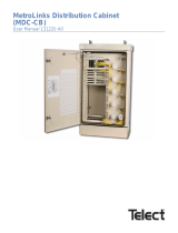
Side B
4.00
(10.16)
(44.37)
17.47
14.00
(35.56)
(27.94)
11.00
(1 of 2 Provided)
Connections
Ground
Optional Rear Cover
(Panel is Shipped Without Breakers.)
Normal Breaker Layout is Shown Here.
RTN B Outputs
}
(1.03)
(ROTATED AND SHOWN WITHOUT
OPTIONAL COVER AND RTN A BUS)
REAR VIEW
}
Side A Breaker Outputs
1/4-20 Stud & KEPS
.750
(1.90)
Center Spacing
for Viewing Breaker
1/4-20 Stud & KEPS
Center Spacing
(1.90)
.750
Outputs
RTN A Bus Removed
Alarm
Board
Hole Dia.
Center Spacing
RTN B Bus
Center Spacing
Hole Dia.
Connection Provided
for Strapping Input
RTN to an Extension
Panel
(1.90)
(3.81)
1.50
.406
.750
.266
(.676)
RTN A Output Terminal Plate
RTN A Input Terminal Plate
-48 A Input Terminal Plate
Side A Breaker Outputs
}
(37.46)
14.75
FRONT VIEW
TOP VIEW
(46.51)
(56.67)
(58.42)
18.31
22.31
23.00
Side A
(17.78)
7.00

Telect, Inc. • USA +1.509.926.6000 • Mexico +1.52.33.3836.3700
Poland +1.48.713.239.100 • UK +1.44.1489.889500 • www.telect.com
Copyright © 2002 Telect, Inc., All Rights Reserved
Page 1-6
Connection Provided
for Strapping Input
BATT to an Extension
Panel
(2.54)
1.00
RTN A Input Terminal
Center Spacing
(2.54)
Hole Dia.
(1.03)
.406
RTN A Input Terminal
(Rotated)
1.00
Use vertical orientation for highest
panel in a top-down input feed or
lowest panel in a bottom-up
input feed.
Input Lug
Mounting
-48 A Input Terminal
Holes
Holes
-48 A Input Terminal
Front of Terminal
Plate
Center Spacing
(1.03)
Holes for Intra-Bay Busing
Hole Dia.
.406
LEFT SIDE VIEW
(3.81)
1.50
Center Spacing
Hole Dia.
(1.03)
.406
(3.81)
Center Spacing
1.50

Telect, Inc. • USA +1.509.926.6000 • Mexico +1.52.33.3836.3700
Poland +1.48.713.239.100 • UK +1.44.1489.889500 • www.telect.com
Copyright © 2002 Telect, Inc., All Rights Reserved
Page 1-7

Telect, Inc. • USA +1.509.926.6000 • Mexico +1.52.33.3836.3700
Poland +1.48.713.239.100 • UK +1.44.1489.889500 • www.telect.com
Copyright © 2002 Telect, Inc., All Rights Reserved
Page 1-8

Telect, Inc. • USA +1.509.926.6000 • Mexico +1.52.33.3836.3700
Poland +1.48.713.239.100 • UK +1.44.1489.889500 • www.telect.com
Copyright © 2002 Telect, Inc., All Rights Reserved
Page 1-9
LUG CHART
Rack Ground Terminals (for #1/0 AWG)
Flex Cable (266 Strand)
Code Cable (19 Strand)
Burndy: YAV25-L2TC14E2-FX
Panduit: LCD2/0-14B-X
Burndy: YA25L-2TC14E2
Panduit: LCD1/0-14B-X
Input Terminals (for 750MCM, Nominal)
Flex Cable (1850 Strand)
Code Cable (61 Strand)
Burndy: YA44-L2NT38-FX
T&B: 58825NT
Burndy: YA39L-2TC38
Load & RTN Terminals (for #2 AWG)
Code Cable (7 Strand) Burndy: YA2CL-2TC14E2
Panduit: LCD2-14B-Q

Telect, Inc. • USA +1.509.926.6000 • Mexico +1.52.33.3836.3700
Poland +1.48.713.239.100 • UK +1.44.1489.889500 • www.telect.com
Copyright © 2002 Telect, Inc., All Rights Reserved
Page 1-10

Telect, Inc. • USA +1.509.926.6000 • Mexico +1.52.33.3836.3700
Poland +1.48.713.239.100 • UK +1.44.1489.889500 • www.telect.com
Copyright © 2002 Telect, Inc., All Rights Reserved • Telect Publication 122645-5 A0
2. Installation
INSTALLATION CONSIDERATIONS
ALERT
!
ALERT! This product must be installed and maintained
only by qualified personnel. Verify all connections
meet requirements specified in local electric codes or
operating company guidelines before supplying power.
Protect this equipment with a fuse or breaker sufficient
to interrupt power levels specified in Section 1 of this
manual.
— Tools and Equipment
•
7
/16 in. (or 12 mm) socket for
1
/4-in. bolts and KEPS nuts
•
9
/16 (or 14 mm) socket for
3
/8-in. bolts and nuts
• #2 Phillips screwdriver (screwdriver for cross-recessed
screws)
• standard electrical cabling tools (cable lacing, crimping
and stripping tools, cable cutters, etc.)
— Technical Support
By e-mail: [email protected]
By phone: 888-821-4856 or 509-921-6161
INSPECTION
Compare the contents of the shipping container with the packing
list. Call Telect if anything is missing.
NOTE
Telect is not liable for shipping damage.
If the shipping container is damaged, keep it for the carrier’s
inspection. Notify the carrier and call Telect’s Customer Ser-
vice Department:
1-800-551-4567 or 1-509-926-6000
Keep the container until you have checked equipment opera-
tion. If you experience any kind of problem, call Telect’s Cus-
tomer Service Department. Use the original, undamaged con-
tainer if you are instructed to return the BDFB / BDCBB to
Telect.
BAY LAYOUT
In a standard bay, each BDFB / BDCBB requires 10 EIA
rack positions (10 RU). Up to four BDFB / BDCBB panels
can populate a bay having either 19-in. or 23-in. racks (ei-
ther EIA or WECO spacing).

Telect, Inc. • USA +1.509.926.6000 • Mexico +1.52.33.3836.3700
Poland +1.48.713.239.100 • UK +1.44.1489.889500 • www.telect.com
Copyright © 2002 Telect, Inc., All Rights Reserved
Page 2-2
PANEL INSTALLATION
1. If applicable, remove optional rear cover of panel (four,
1
/4-20 hexhead bolts).
2. Decide if input cables will be fed from bottom-up or top-down.
NOTE
Panels are shipped from the factory for top-down input cable entrance to bay. If you intend to feed input cables from the bottom-
up, you must reverse the input terminal plates, as instructed in the following procedure.
If necessary, to change both input buses from top-down to bottom-up input cable entrance, refer to the following illustration and
proceed as follows:
a. Remove four,
3
/8-in. hex head cap screws securing each input bus assembly to panel.
b. Rotate this assembly for input bus A and resecure it where the bus B had been, and vice versa.
c. Torque bolts to 18 ft-lb (~24 N•m).

Telect, Inc. • USA +1.509.926.6000 • Mexico +1.52.33.3836.3700
Poland +1.48.713.239.100 • UK +1.44.1489.889500 • www.telect.com
Copyright © 2002 Telect, Inc., All Rights Reserved
Page 2-3
3. If panel is to be mounted to a 19-in rack, remove adapter plate on each side of
the panel (five,
1
/4-20 KEPS nuts).
4. If applicable, install optional shunts and cabling for current monitor. (See instructions included with shunt kit.)

Telect, Inc. • USA +1.509.926.6000 • Mexico +1.52.33.3836.3700
Poland +1.48.713.239.100 • UK +1.44.1489.889500 • www.telect.com
Copyright © 2002 Telect, Inc., All Rights Reserved
Page 2-4
5. If applicable, install optional digital metering control module in place of standard control module. (See instructions included with
metering control module.)
6. Partially thread two topmost fasteners (#12-20 screws, provided) for mounting panel onto bay.
7. Place panel’s keyhole mounting slots over topmost fasteners.
8. Loosely secure the mounting flange with four additional fasteners along each side.
9. Torque all but keyhole mounting fasteners to 35 in.-lb (4.29 N•m).
10. Remove keyhole fasteners installed in Step 4, and re-install along with a flat washer and a lock washer. Torque as directed in
Step 9.
11. Install all other panels in bay before cabling.
CABLE INSTALLATION
Use Telect’s Wire Size Guide (117995) for help in cable selection.
NOTE
Cables must conform to local operating company guidelines as well as national, regional, and local electrical codes.
Only use components and crimping tools approved by agencies or certifying bodies recognized in your country or region such
as Underwriter’s Laboratories (UL), TUV, etc.

Telect, Inc. • USA +1.509.926.6000 • Mexico +1.52.33.3836.3700
Poland +1.48.713.239.100 • UK +1.44.1489.889500 • www.telect.com
Copyright © 2002 Telect, Inc., All Rights Reserved
Page 2-5
Follow the prescribed order in this subsection to install and test all cabling and alarm features:
A.Install Ground Cabling
B.Install Input Cabling
C.Install Intrabay & Interbay Cabling
D. Install Alarm Cabling
E.Test Inputs and Alarms Without Circuit Breakers
F.Install Output Cabling
— A. Install Ground Cabling
DANGER
!
DANGER! DANGER! Failure to properly ground this equipment can create hazardous conditions to installa-
tion personnel and to the equipment.
GEFAHR! Bei unsachgemäßer Erdung besteht Gefahr für das Installationspersonal und das Gerät!
¡PELIGRO! La conexión incorrecta a tierra puede ser peligrosa tanto para los instaladores como para el equi-
po.
DANGER ! Si vous ne reliez pas correctement cet équipement à la terre, son utilisation présente des dangers
pour la personne qui l'installe ainsi que pour l'équipement.
A ground terminal is located near each of the panel’s mounting flanges. You need only connect to one of the grounds, as shown in
the following illustration.
1. Use a UL-approved crimping tool to attach a UL-approved, 2-hole compression lug onto a ground wire.
Size of ground depends on input interruption device.
1
2. Lightly coat anti-oxidant electrical joint compound on lug, grounding terminal, and surrounding contacting surface. Then, con-
nect lug to terminal using
1
/4-in. KEPS nuts and washers from studs.
1. Refer to NEC Article 250-122 or IEEE grounding guidelines. Also, check operating company guidelines.

Telect, Inc. • USA +1.509.926.6000 • Mexico +1.52.33.3836.3700
Poland +1.48.713.239.100 • UK +1.44.1489.889500 • www.telect.com
Copyright © 2002 Telect, Inc., All Rights Reserved
Page 2-6
3. Torque ground connection to 6 ft-lb (8.13 N•m).
4. Likewise, secure the connectorized opposite end of the ground cable to a bare metal portion of the bay’s frame or the conduc-
tor-to-office-ground system. (If necessary scrape paint from the frame and use electrical joint compound to ensure good ground
contact.)
— B. Install Input Cabling
• For top-down input feeds, begin cabling to the topmost panel and then work your way down the bay.
• For bottom-up input feeds, begin at the bottom and work your way up the bay.
Finish all input cabling in a bay before beginning any output cabling in that same bay.
NOTES
• Keep in mind that Feeds A and B are independent (unshared) feeds.
• Input cabling to the BDFB / BDCBB must support 125% of the total, rated, continuous load currents of the equipment
powered by the BDFB / BDCBB. Remember: The maximum continuous load per feed is 600A.
• Consider inherent voltage drop in determining input wire size. Remember to choose wire size based on the circuit break-
er/fuse size and not
on the expected load. Use the standard formula to check wire size:
Max.Vdc Drop =
(11.1) x (fuse size) x (total wire length in ft)
(circular mils of wire used)
Proceed as follows to cable inputs to each side of the panel:
1. Use a UL-approved crimping tool to attach a UL-approved, dual-hole 750/777.7 MCM compression lugs onto appropriate
cables. Insulate lug barrels as required.
2. Clean terminals and lugs with a nonabrasive, nonmetallic pad.
3. Feed input cabling down (or up for a bottomfeed) into the rear central area of the panel — that is, between the output cable
management brackets — to the topmost BDFB / BDCBB (or bottommost for an upfeed).
4. Lightly coat anti-oxidant electrical joint compound on lugs and -48 input terminal plates.
5. Use a
3
/8-16, grade 2 bolt, washers, and nut (all provided) to secure the first pair of -48 cabling to the -48 input bus terminal
plate:
• If two lugs are used, remember to attach lugs to opposite faces of the terminal plate. DON’T STACK LUGS on one side of
the terminal plate.
• Always route cables in a neat orderly manner to ensure that the cables exert no pulling or twisting forces on the input and
return terminal plates. DON’T ALLOW TERMINAL PLATES to support the weight of or to restrain the cable.
NOTE
The input lugs on the topmost terminal (or bottommost for an upfeed) are connected, as shown on the following page, so that
the lugs are held straight up on the sides of the terminal plate. Subsequent cables and lugs to the inbetween panels in the bay
can be pivoted up to 25º off of vertical to allow easier cable management access throughout the bay.
/