Page is loading ...


ii
IMPORTANT
WARNING: IMPROPER INSTALLATION, ADJUSTMENT,
ALTERATION, SERVICE OR MAINTENANCE CAN CAUSE
PROPERTY DAMAGE, INJURY OR DEATH. READ THE
INSTALLATION, OPERATING AND MAINTENANCE IN-
STRUCTIONS THOROUGHLY BEFORE INSTALLING OR
SERVICING THIS EQUIPMENT
FOR YOUR SAFETY
Do not store or use gasoline or other flammable vapors
or liquids in the vicinity of this or any other appliance.
The information contained in this manual is important for the proper
installation, use, and maintenance of this oven. Adherence to these
procedures and instructions will result in satisfactory baking results
and long, trouble free service. Please read thismanual carefully and
retain it for future reference.
Errors: Descriptive, typographic or pictorial errors are subject to
correction. Specifications are subject to change without notice.
PDF compression, OCR, web optimization using a watermarked evaluation copy of CVISION PDFCompressor

iii
THE REPUTATION YOU CAN COUNT ON
For over a century and a half, The Blodgett Oven Company has been building
ovens and nothing but ovens. We’ve set the industry’s quality standard for all
kinds of ovens for every foodservice operation regardless of size, application
or budget. In fact, no one offers more models, sizes, and oven applications than
Blodgett; gas and electric, full-size, half-size, countertop and deck, con-
vection, Cook’n Hold, Combi-Ovens and the industry’s highest quality Pizza
Oven line. For more information on the full line of Blodgett ovens contact your
Blodgett representative.
PDF compression, OCR, web optimization using a watermarked evaluation copy of CVISION PDFCompressor


v
NOTE
Wiring Diagrams are in Section 7 of this Manual.
The diagram for each oven is also on the lower
inner surface of its Control Console.
TABLE OF CONTENTS
Page
SECTION 1
I. MODEL IDENTIFICATION .............................................. 1
SERIES BE3240 ELECTRICAL SPECIFICATIONS....... 2
II. PRINCIPLE OF AIR FLOW ............................................. 3
A. Heat Transfer and How It Works .............................. 3
II. PRINCIPLE OF AIR FLOW (Continued) ........................ 4
B. Air Fingers ................................................................. 4
III. COMPONENT FUNCTION ............................................ 5
A. Conveyor Motor and Conveyor Belt ........................ 6
B. Blower Fan ................................................................. 6
C. Electric Heaters ........................................................ 6
D. Window ....................................................................... 6
E. Cooling Fan ................................................................ 7
F. Air Fingers and Blank Plates - See Figure 1-9 ......... 8
SECTION 2
I. UNLOADING ................................................................... 9
BE3240 OVEN INSTALLATION
REQUIRED KITS AND EQUIPMENT ........................ 10
PARTS LIST FOR SERIES BE3240 ELECTRIC OVEN
INSTALLATION KIT ................................................ 1 0
PARTS LIST FOR BE3240 SERIES SINGLE OVEN
OPTION - BASE W/15
″″
″″
″ LEGS & TOP P/N 34832 ..... 11
PARTS LIST FOR BE3240 SERIES DOUBLE OVEN
OPTION - BASE W/6″ LEGS,CASTERS & TOP
P/N 34833 ................................................................ 12
PARTS LIST FOR BE3240 SERIES DOUBLE OVEN
OPTION - BASE W/CASTERS & TOP
P/N 34831 ................................................................ 13
PARTS LIST FOR BE3240 SERIES TRIPLE OVEN
OPTION - BASE w/OUTRIGGERS & TOP
P/N 51139 ................................................................... 14
RESTRAINT CABLE INSTALLATION.......................... 17
UTILITY ROUGH-IN DIMENSIONS AND POSITIONING
FOR BE3240-SERIES OVENS .................................... 18
CIRCUIT BREAKER ..................................................... 18
ELECTRICAL SPECIFICATIONS ................................. 18
ELECTRICAL RATING ................................................. 18
SUPPLY WIRE .............................................................. 18
SUGGESTED ................................................................ 18
II. VENTILATION GUIDELINES .................................... 19
VENTILATION HOOD ................................................... 19
VENTILATION CAPTURE TEST................................... 19
III. ELECTRICAL CONNECTION INFORMATION FOR
BE3240-SERIES OVENS. ........................................... 20
IV. ELECTRIC SUPPLY FOR ELECTRIC-HEATED
OVENS ...................................................................... 20
V. CONVEYOR REAR STOP AND
END STOP INSTALLATION ...................................... 21
SECTION 3 INSTALLATION
I. CONTROL FUNCTIONS ................................................ 23
II. COMPONENT INFORMATION AND LOCATION ......... 24
A. Door Safety Switch .................................................. 24
B. Blower/Heat Switch ............................................ 24
C. Temperature Controller .......................................... 24
D. Conveyor ................................................................. 25
MEASURING CONVEYOR SPEED. ............................. 25
III. STEP-BY-STEP OPERATION ..................................... 26
A. Startup Procedures ................................................. 26
TABLE OF CONTENTS
(Continued)
Page
Daily Startup ................................................................. 26
Power Failure ............................................................... 26
B. Shutdown Procedure ...................................................... 26
SECTION 3 INSTALLATION (Continued)
IV. NORMAL OPERATION - STEP-BY-STEP .................. 28
A.Daily Startup Procedure .......................................... 28
V. QUICK REFERENCE: TROUBLESHOOTING ............. 30
SECTION 4 MAINTENANCE
I. MAINTENANCE - DAILY ........................................... 32
A. Exterior .................................................................... 32
B. Cooling Fan .............................................................. 32
C. Conveyor Belt ......................................................... 32
D. Crumb Pans ............................................................ 32
E. Window .................................................................... 32
II. MAINTENANCE - MONTHLY ...................................... 33
A. Removing Conveyor From Oven For Cleaning .... 33
B. Air Fingers Disassembly For Cleaning ................. 35
C. Reassembly of Air Fingers .................................... 36
D. Reinstall End Plugs ................................................. 39
E. Conveyor Reassembly Into Oven.......................... 40
F. Checking Conveyor Belt Tension ......................... 40
G. Conveyor Belt Link Removal ................................ 41
H. Replacing Conveyor Belt ......................................... 42
I. Attaching Drive Chain ............................................ 42
III. MAINTENANCE - EVERY 3 MONTHS ........................ 43
A. Cleaning the Blower/Fan Motor ............................. 43
B. Electrical Terminals ............................................... 44
C. Ventilation ............................................................... 44
D. Checking the Blower/Fan Belt ............................... 44
E. Blower Fan Shaft Bearing Lubrication .................. 45
F. Split-belt Conveyor Shaft Cleaning ........................ 45
IV. MAINTENANCE - EVERY 6 MONTHS .................... 46
BE3240-SERIES ELECTRIC OVEN KEY SPARE
PARTS ...................................................................... 48
KEY SPARE PARTS KIT .............................................. 48
SECTION 5 TROUBLESHOOTING
Troubleshooting Charts ..................................................... 49
SECTION 6 - PARTS LIST
OVEN PANELS, WINDOW AND LEGS ............................ 53
CONTROL PANEL ........................................................... 55
BLOWER AND SHROUD ................................................. 57
CONVEYOR...................................................................... 59
SPLIT BELT CONVEYOR ................................................. 61
MACHINERY COMPARTMENT ....................................... 63
SECTION 7 ELECTRICAL SCHEMATICS
Wiring Diagram, E208-240 50/60, 3PH 4W BE3240 ........ 65
Wiring Diagram, E380-480 50/60, 3PH 5W BE3240 ........ 66
Wiring Diagram, E380V 50/60, 3PH 5W BE3240 .......... 67
PDF compression, OCR, web optimization using a watermarked evaluation copy of CVISION PDFCompressor


SECTION 1
DESCRIPTION
1
I. MODEL IDENTIFICATION
The Blodgett BE3240-Series may be used either as a
single oven or stacked for use as double or triple ovens.
The major difference between the oven models in this
series is the width of the conveyor.
A single BE3240-Series Oven (Figure 1-1) is mounted on a
base pad with legs and casters. A double oven (Figure 1-2)
consists of two,
stacked,
single ovens. A triple oven
(Figure 1-3) consists of three stacked single ovens. The
lower oven is mounted on a base pad with short legs and
casters.
On a double or triple oven, the ovens operate completely
independent. All ovens use identical controls and compo-
nents. One oven can be cleaned or serviced, while the
others are operating.
SECTION 1
DESCRIPTION
Figure 1-1. Single BE3240 Oven
Figure 1-2. Double BE3240 Oven
Figure 1-3. Triple BE3240 Oven
PDF compression, OCR, web optimization using a watermarked evaluation copy of CVISION PDFCompressor


SECTION 1
DESCRIPTION
3
II. PRINCIPLE OF AIR FLOW
The fan-style blower draws air into the oven plenum where
it is heated. The blower then pushes the hot air through the
air fingers into the baking chamber. Each air finger
contains an inner plate and outer plate that form the hot air
into jets, distributing it across a conveyor belt on which the
food product rides. Air is then pulled back into the blower
and the process continues. The curving, black arrows of
Figure 1-4 show this air flow.
A. Heat Transfer and How It Works
1. Heat constantly moves from a warm object to a cold
object. Heat moves using three different paths: Conduc-
tion; Radiation; and Convection.
Conduction:
This path utilizes surface-to-surface con-
tact. The pizza dough in contact with the pan is a good
example of conduction.
Radiation:
This path has to do with objects radiating heat.
Dark objects absorb heat whereas light or shiny objects
reflect more heat. This is the reason that the inside of a
BE3240-Series Oven is light in color: To reflect more heat
back onto the food product.
Convection:
This path has to do with moving a volume of
air. It explains why hot air rises and cooler air replaces hot
air. An industrial application of this principle is to incorpo-
rate a fan to force the hot air movement, which in turn
increases the heat transfer to the food product.
Each BE3240-Series Oven has a large fan-style blower to
move the hot air through the air fingers and onto the
product to cook/bake the food product most efficiently.
2. Temperature is the intensity of heat at the point where
it is sensed. As discussed above, heat flows by conduc-
tion, radiation and convection. The speed at which the heat
flows is determined by the temperature difference between
the oven and the food product. The larger the difference,
the faster the heat flows to the item that is being baked.
Upper Air Fingers
Lower Air Fingers
Conveyor Belt(s)
Window
Figure 1-4. BE3240-Series Oven Air Flow
PDF compression, OCR, web optimization using a watermarked evaluation copy of CVISION PDFCompressor

4
SECTION 1
DESCRIPTION
Series ovens used to bake pizza have four bottom fingers
and two top fingers. For special product baking require-
ments, a number of other styles of fingers and finger
arrangements are available from the factory.
NOTE:
Some customers have a predetermined finger
arrangement. If you have any questions pertaining to the
finger arrangement, please call the factory.
Air Flow
From Plenum
Manifold
Manifold Baffle
Outer Plate
Inner Plate
Air Flow
From Plenum
Manifold
Manifold Baffle
Outer Plate
Inner Plate
High Velocity
Columns of Air
on Food Product
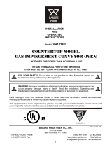
II. PRINCIPLE OF AIR FLOW (Continued)
B. Air Fingers
The BE3240-Series Ovens are conveyorized ovens that
employ vertical jets of hot air streaming from air fingers
(Figure 1-5) to give uniform, intense heating. The vertical
streams of hot air provide an exceptional heat transfer rate
and generally bake faster and at lower temperatures than
convection hot air or infrared heating ovens.
A BE3240-Series Oven can accommodate up to four
bottom air fingers and four top air fingers. Some BE3240-
Figure 1-5. Air Fingers, Showing High-Velocity Columns of Air Formed During Passage Through
the Inner Plate and Outer Plate to Heat the Food Product.
PDF compression, OCR, web optimization using a watermarked evaluation copy of CVISION PDFCompressor


6
SECTION 1
DESCRIPTION
III. COMPONENT FUNCTION
A. Conveyor Motor and Conveyor Belt
The conveyor belt is driven by a variable-speed electric
motor (Figure 1-7) operating through a gear reducer. The
motor speed is controlled by a digital control. The stain-
less-steel wire belt can travel in either direction at variable
rates ranging from 3 minutes to 30 minutes; this is the time
that a product can take to pass through the oven.
B. Blower Fan
The blower fan is located at the rear of the oven. This
blower forces heated air through the air fingers. The
BLOWER/HEAT switch must be set to “ON” or “I” for oven
warmup and baking.
C. Electric Burner
There are six heater elements mounted on the inside of the
rear panel. Each element is connected to an electrical
control which is energized by the temperature controller.
D. Window
A window on the front of the oven permits viewing the items
being baked and provides access to the oven for items that
do not require full baking time, such as sandwiches,
cookies, small items, or cheese-melting processes.
E. Cooling Fan — See Figure 1-8
The cooling fans are located in the back of the oven.
These cooling fans draw air through its grille, blowing it
through the blower motor compartment and the control
compartment into the oven top and exhausted out the front
louvers.
F. Air Fingers and Blank Plates - See Figure 1-9
F1. Air Fingers
An Air Finger Assembly is made up of three parts:
1. Outer Plate - The Outer Plate is the removable covering
with tapered holes, which direct the air stream onto the
product being baked.
2. Inner Plate -The perforated Inner Plate is vital in forming
the unique air jets. It must be assembled into the manifold
with its holes aligned with the holes of the outer plate.
3. Manifold - The Manifold is the assembly which slides
on tracks into the oven plenum.
Figure 1-7. Machinery Compartment
Components
PDF compression, OCR, web optimization using a watermarked evaluation copy of CVISION PDFCompressor


8
SECTION 1
DESCRIPTION
Half Blank Plate
Blank Plate
Outer Plate
Inner Plate
Finger
Manifold
Assembly
Baffle
Figure 1-9. Blank Plates (two sizes) and an Air Finger.
F2. Blank Plates
1. Blank Plates- The Blank Plates are available to install
on the plenum where an air finger is not required.
PDF compression, OCR, web optimization using a watermarked evaluation copy of CVISION PDFCompressor

SECTION 2
INSTALLATION
9
SECTION 2
INSTALLATION
NOTE: The oven, when installed, must be electrically
grounded in accordance with local codes, or in the ab-
sence of local codes, with the National Electrical Code
(NEC), or ANSI/NFPA70.
NOTE
There must be adequate clearance between
the oven and any adjacent combustible con-
struction. Clearance must also be provided
for servicing and for operation.
CAUTION
It is required that the oven be placed under a
ventilation hood for adequate air supply and
ventilation.
CAUTION
Do not obstruct the flow of combustion and
ventilation air to and from your oven. Do not
obstruct the ventilation holes in the Control Panel.
CAUTION
On ovens with the Machinery Drive Compartment
located at the right end, a minimum clearance of
0″ to a left side wall, 18″ to a right side wall and 6″
from a back wall to air openings at the rear of the
oven must be maintained. On ovens with the
machinery/drive compartment located at the left
end, a minimum clearance of 0″ to a right side
wall, 18″ to a left side wall and 6″ from a back wall
to air openings at the rear of the oven must be
maintained.
For servicing and cleaning, a minimum of 18″
clearance from all walls is recommended.
I. UNLOADING
Your Blodgett BE3240-Series Oven is shipped partially
assembled. It will arrive in a carton on a crate.
Carton size for a BE3240-Series Oven is:
84″ (2134mm) Long ×
58″ (1473mm) Wide ×
44″ (1118mm) High ×
The crate and carton must be examined before signing the
Bill of Lading. Report any visible damage to the transport
company, and check for the proper number of crates. If
apparent damage is found, make arrangements to file a
claim against the carrier. Surface Interstate Commerce
Regulations (U.S.A.) require that the claim must be
initiated by the consignee within 10 days from the date that
the shipment is received.
A Pre-installation Procedures Manual is attached to the
exterior wall of the carton. This manual contains detailed
instructions on unpacking and moving the oven(s) to the
operating site. When the transport company notifies you of an
impending delivery, arrange to have a forklift at your facility
to unload the carton(s).
Instructions for stacking the ovens is continued in a
separate manual used by Blodgett Authorized Installers.
If you have a door wider than the carton, simply move the
carton into your facility and arrange an appointment with
your Blodgett Authorized Installer.
If your door is narrower than the carton, then the oven will
have to be unpacked. Follow the directions shown in the
Pre-Installation Procedures Manual.
PDF compression, OCR, web optimization using a watermarked evaluation copy of CVISION PDFCompressor

10
SECTION 2
INSTALLATION
BE3240 OVEN INSTALLATION
REQUIRED KITS AND EQUIPMENT
TYPE BE3240 BE3240 Single BE3240 Double BE3240 Double BE3240 Triple
OF Gas Oven Oven Option Oven Option Oven Option Oven Option
INSTALLATION Installation Base w/15″
Legs, Base w/6″
Legs, Base w/Casters Base w/Casters
Kit P/N Casters & Top Casters & Top & Top & Top
50663 Kit P/N Kit P/N Kit P/N Kit P/N
34832 34833 34831 51139
BE3240 Single Gas Oven 1 1
BE3240 Double Gas Oven 2 1 1
BE3240 Triple Gas Oven 3 1
PARTS LIST FOR SERIES BE3240 GAS OVEN
INSTALLATION KIT
P/N 50633
(Two required for double oven)
(Three required for triple oven)
ITEM
NO. QTY PART NO. DESCRIPTION
1 1 33900-0032 FLEXIBLE GAS HOSE
2 1 35000-1103 CONVEYOR END STOP
3 1 35900-0148 CONVEYOR LEFT REAR STOP
4 1 50664 SERIES BE3240 OWNER/OPERATOR MANUAL
5 1 1002040 SERVICE AGENCY DIRECTORY
Figure 2-1. BE3240-Series Gas Oven
Installation Parts
PDF compression, OCR, web optimization using a watermarked evaluation copy of CVISION PDFCompressor

SECTION 2
INSTALLATION
11
PARTS LIST FOR BE3240 SERIES SINGLE OVEN OPTION - BASE w/15² LEGS & TOP
P/N 34832
ITEM
NO. QTY PART NO. DESCRIPTION
1 1 37900-0025 COMPLETE BASE WELDMENT
2 4 37900-0024 TOP PLATE, LEG WELDMENT
3 2 22290-0009 SWIVEL CASTER W/BRAKE FLAT PLATE
4 2 22290-0010 SWIVEL CASTER FLAT PLATE
5 32 220373 3/8″-16 × 1″ HEX SCREW,SST
6 32 21416-0001 3/8″ FLAT WASHER, SS
7 32 21422-0001 3/8″ SPLIT LOCK WASHER, ZP
8 4 21256-0008 SCREWS FOR TOP 10-32 × 3/8″ 18-8, SL TRUS S
9 1 22450-0228 RESTRAINT CABLE ASSEMBLY
10 1 33486 TOP COVER 304 PANEL
Figure 2-2. Model BE3240 Single Oven
Option Base with Legs and Top
PDF compression, OCR, web optimization using a watermarked evaluation copy of CVISION PDFCompressor

12
SECTION 2
INSTALLATION
PARTS LIST FOR BE3240 SERIES DOUBLE OVEN OPTION - BASE w/6
″″
″″
″ LEGS, CASTERS & TOP
P/N 34833
ITEM
NO. QTY PART NO. DESCRIPTION
1 1 37900-0025 COMPLETE BASE WELDMENT
2 4 37900-0102 TOP PLATE, LEG WELDMENT
3 2 22290-0009 SWIVEL CASTER W/BRAKE FLAT PLATE
4 2 22290-0010 SWIVEL CASTER FLAT PLATE
5 32 220373 3/8″-16 × 1″ HEX SCREW,SST
6 32 21416-0001 3/8″ FLAT WASHER, SS
7 32 21422-0001 3/8″ SPLIT LOCK WASHER, ZP
8 4 21256-0008 SCREWS FOR TOP 10-32 × 3/8″ 18-8, SL TRUS S
9 1 22450-0228 RESTRAINT CABLE ASSEMBLY
10 1 33486 TOP COVER 304 PANEL
Figure 2-3. Model BE3240 Double Oven
Option Base with Legs and Top
PDF compression, OCR, web optimization using a watermarked evaluation copy of CVISION PDFCompressor

SECTION 2
INSTALLATION
13
PARTS LIST FOR BE3240 SERIES DOUBLE OVEN OPTION - BASE w/CASTERS & TOP
P/N 34831
ITEM
NO. QTY PART NO. DESCRIPTION
1 1 37900-0025 COMPLETE BASE WELDMENT
2 2 22290-0009 SWIVEL CASTER W/BRAKE FLAT PLATE
3 2 22290-0010 SWIVEL CASTER FLAT PLATE
4 32 220373 3/8″-16 × 1″ HEX SCREW,SST
5 32 21416-0001 3/8″ FLAT WASHER, SS
6 32 21422-0001 3/8″ SPLIT LOCK WASHER, ZP
7 4 21256-0008 SCREWS FOR TOP 10-32 × 3/8″ 18-8, SL TRUS S
8 1 22450-0228 RESTRAINT CABLE ASSEMBLY
9 1 33486 TOP COVER 304 PANEL
Figure 2-4. Model BE3240 Double Oven
Option Base with Casters and Top
PDF compression, OCR, web optimization using a watermarked evaluation copy of CVISION PDFCompressor

14
SECTION 2
INSTALLATION
PARTS LIST FOR BE3240 SERIES TRIPLE OVEN OPTION - BASE w/CASTERS & TOP
P/N 51139
ITEM
NO. QTY PART NO. DESCRIPTION
1 1 54606 COMPLETE BASE WELDMENT
2 4 45209 QUAD OUTRIGGER WELDMENT
3 2 22290-0009 SWIVEL CASTER, W/BRAKE FLAT PLATE
4 2 22290-0010 SWIVEL CASTER, FLAT PLATE
5 4 45206 INSERT,QUAD ADJUSTMENT FOOT
6 4 45205 SPACER,QUAD CASTER
7 32 220373 3/8″-16 × 1″ HEX BOLT, SST
8 32 21416-0001 3/8″ FLAT WASHER, SS
9 32 21422-0001 3/8″ SPLIT LOCK WASHER, ZP
10 16 21172-0004 3/8″-16 NYLON INSULATED LOCKNUT, ZC
11 8 21216-0018 1/2″-13 × 1-1/4″ 18-8 HEX CAPSCREW
12 8 21416-0003 1/2″ 18-8 FLAT WASHER
13 8 21426-0004 1/2″ 18-8 LOCK WASHER
14 4 21256-0008 SCREWS FOR TOP 10-32 × 3/8″ 18-8, SL TRUS S
15 1 22450-0228 RESTRAINT CABLE ASSEMBLY
16 1 33486 TOP COVER 304 PANEL
Figure 2-5. Model BE3240 Triple Oven
Option Base with Outriggers and Top
PDF compression, OCR, web optimization using a watermarked evaluation copy of CVISION PDFCompressor
/