
BLODGETT OVEN COMPANY
www.blodgettcorp.com
50 Lakeside Avenue, Box 586, Burlington, Vermont 05402 USA Telephone (800) 331-5842, (802) 860-3700 Fax: (802)864-0183
PN M7016 Rev C (6/01)
E 2000 --- G.S. Blodgett Corporation
MT3870
CONVEYOR OVENS
INSTALLATION -- OPERATION -- MAINTENANCE
MT3870
FOURS À BAND E TR ANSPOR TEUSE
MANUEL D’INSTALLATION -- FONCTIONNEMENT -- ENTRETIEN
Page is loading ...
Page is loading ...

Your Service Agency’s Address:
Adressedevotreagencedeservice:
Model/Modèl:
Serial Number/Numéro de série:
Your oven was installed by/
Installateur de votre four:
Your oven’s installation was checked by/
Contrôleur de l’installation de votre four:

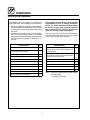
Table of Contents/Table des Matières
Introduction
Oven Description and Specifications 2....
Oven Components 3....................
Installation
Delivery and Inspection 4...............
Oven Location and Ventilation 5..........
Oven Assembly 6......................
Oven Supports and Casters 6..........
Return Air Diverters 6..................
Nozzles 7............................
Conveyor Belt Supports 7..............
Conveyor Belt 8......................
End Plugs 10..........................
Conveyor Belt Tensioner 10.............
Crumb Pans 11........................
Remote Computer Control 11...........
Utility Connections ---
Standards and Codes 12.................
Gas Connection 13......................
Electrical Connection 16.................
Operation
Safety In formation 17....................
Cooking Computer 18...................
Oven Adjustments for Cooking 20.........
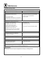
Maintenance
Cleaning 21............................
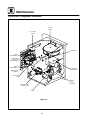
Control Box Component Locations 24......
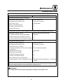
Troubleshooting Guide 25................
Introduction
Description et Spécifications du Four 28....
Éléments du Four 29.....................
Installation
Livraison et Inspection 31................
Implantation et aération du four 32........
Montage du Four 33.....................
LesSupportsduFouretlesRoulettes 33.
Déviateurs de l’Air en Retour 33.........
Les Buses 34..........................
Le Support de Bande Transporteuse 34..
La Bande Transporteuse Métallique 35...
Les Arrêtoir 37.........................
Tendeurs du Tapis 37...................
Plateaux pour Miettes 38...............
L’Ordinateur de Cuisson Détaché 38.....
Branchements de Service ---
Normes et Codes 39.....................
Branchement de Gaz 40.................
Raccordement Électrique 43..............
Utilisation
Informations de Sécurité 44...............
L’Ordinateur de Cuisson 45...............
Ajustements du four pour la cuisson 47....
Entretien
Nettoyage 49...........................
Emplacements des Composants du
Boîtier de Commande 52.................
GuidedeDétectiondesPannes 53........

Introduction
2
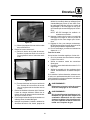
Oven Description and Specifications
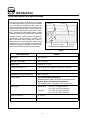
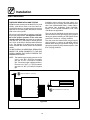
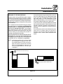
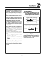
Cooking in a conveyor oven differs from cooking
in a conventional deck or range oven since heated
air is constantly recirculated over the product by
a fan in an enclosed chamber. The moving air con -
tinually strips away the layer of cool air surround-
ing the product, quickly allowing the heat to pene -
trate. The result is a high quality product, cooked
at a lower temperature in a shorter amount of time.
Blodgett conveyor ovens represent the latest ad-
vancement in energy efficiency, reliability, and
ease of operation. Heat normally lost, is recircu-
lated within the cooking chamber before being
vented from the oven: resulting in substantial re-
ductions in energy consumption, a cooler kitchen
environment and enhanced oven performance.
AirFlowPatternforBlodgettConveyorOvens
Heated Air Conveyor
Combustion Chamber
Return Air
Figure 1
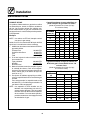
SPECIFICATIONS
MT3870
Belt Width 38” (96.5 cm)
Cooking Zone Length 70” (177.8 cm)
Baking Area 18.5 Sq. Ft. (1.7 m
2
)
Dimensions (single unit) 106” x 62.54” x 44” (269 cm x 162.5 cm x 112 cm)
Maximum Input 150, 000 BTU/Hr. (43.9 kW/Hr.) (158 MJ/Hr.)
Maximum Operating Temperature 600
_
F (315
_
C)
Power Supply U.S. and Canadian installations:
120/208-240VAC, 60Hz., 1Φ, 9 Amp, 3 wire with ground
General Export and Australian installations:
220-240VAC, 50Hz., 1Φ, 9 Amp, 3 wire with ground
Gas Supply Natural Gas: 4.5” W.C. (1.1 kPa) minimum
10.5” W.C. (2.61 kPa) ma ximum
Propane: 11.0” W.C. (2.74 kPa) minimum
13.0” W.C. (3.2 kPa) maximum
Product Clearance 3” (7.6 cm)
Gas Supply Connection 3.25” (8.3 cm)

Introduction
3
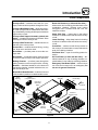
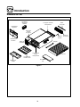
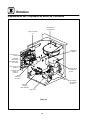
Oven Components
Conveyor Belt --- stainless steel chain link (con -
veyor) belt that carries product through the oven.
Conveyor Belt Master Links --- a ll ow e a sy r em ov -
al of the conveyor belt for maintenance and clean-
ing. Identified by locating double spaces between
regular links on belt.
Conveyor Belt Support Assembly (drive & idle
sides) ---locatedonbothendsofovendeck.Drive
side support drives conveyor belt.
Conveyor Belt Tensioners --- maintain tension on
theendoftheconveyorbelt.
Control Box --- contains electrical wiring, cooling
fan, drive motor and drive chain.
Drive Motor --- provides power to move the con-
veyor belt.
Drive Chain --- connects the drive motor sprocket
to the drive side conveyor belt support sprocket.
Baking Chamber --- products pass through the
baking chamber on the conveyor belt for cooking.
Nozzles --- distribute heated air to the bottom of
the baking chamber. Located inside the oven, un-
der the conveyor belt.
Nozzle Hold- Down Bracket --- holds the front end
of the nozzles in position. Located inside the oven.
Return Air Diverters (2, drive and idle sides) ---
diverts return a ir from baking chamber back to the
combustion chamber. Ensures even baking
throughout oven. Located inside the oven, be-
neath the nozzles.
Upper End Plug --- keeps heat in the baking
chamber. Located on each end above the convey-
or belt.
Lower End Plug --- helps keep heat in the baking
chamber. Located at each end below the convey-
or belt.
Crumb Pan --- catches crumbs from products on
the conveyor. Located under conveyor belt at both
ends of the baking chamber.
Pull Down Door --- open for auxiliary product in-
sertion.
Air Flow Plates (2, drive and idle sides) --- d i s -
tribute heated air to top of baking chamber. Lo-
cated inside of oven at the top of baking chamber.
Emergency Shut Down Switch --- a l low s u s er t o
turn oven and conveyor off in an emergency. Do
not use f or general shut down.
Conveyor Support
Assembly
Air Flow
Plate
Remote
Computer Control
Handle for
Pull Down Door
Crumb
Pan
Product Stop
Control
Box
Return Air
Diverters
Nozzles
Upper
End Plug
Lower
End Plug
Emergency
Shut Down
Switch
Conveyor
Support
Assembly
Conveyor Belt
Belt
Tensioner
Figure 2

Installation
4
Delivery and Inspection
All Blodgett ovens are shipped in containers to
prevent damage. Upon delivery of your new oven:
D
Inspect the shipping container for external dam-
age. Any evidence of damage should be noted
on the delivery receipt which must be signed by
the driver.
D
Uncrate the oven and check for internal dam-
age. Carriers will accept claims for concealed
damage if notified within fifteen days of delivery
and the shipping container is retained for in-
spection.
The Blodgett Oven Company cannot assume
responsibility for loss or damage suffered in
transit. The carrier assumed full responsibility
for delivery in good order when the shipment
was accepted. We are, however, prepared to
assist you if filing a cl aim is necessary.
The oven can now be moved to the installation
site. Check the following list with Figure 2 on page
3 to be sure all items w ere received.
Part Description
Qty.
Main oven body 1
Oven support/with caster
(2 locking, 2 non-locking)
4*
Left conveyor support assembly 1
Right conveyor support assembly 1
Upper end plug assembly 2
Low er end plug assembly 2
Rolled wire belt 1
Crumb pan 2
Nozzles 14
Product stop 1
Air flow plate removal handle 1*
Part Description Qty.
Packet containing:
3/8”-16 bolts, flat & lock washers for
oven supports
1*
Packet containing:
(2) glass DC fuses & control board fuse
Conveyor belt master links
1*
Extra piece of wire conveyor belt 1*
Owner’s manual 1*
Return air diverters 2
Remote oven control with cables 1
Belt tensioners 2
NOTE: Units may include a false front with a differ-
ent style handle.
* not shown in Figure 2.

Installation
5
Oven Location and Ventilation
LOCATION
The well planned and proper placement of your
oven will result in long term operator convenience
and satisfactory performance.
The following clearances must be maintained be-
tween the oven and any combustible or non-com-
bustible construction.
D
Oven body sides --- 20” (50.8 cm)
D
Oven body back --- 2” (5 cm)
The following clearances must be available for ser-
vicing.
D
Oven body sides --- 38” (96.5 cm)
D
Oven body back --- 28” (71 cm)
NOTE: On gas models, routine servicing can usu -
ally be accomplished within the limited
movement provided by the gas hose re-
straint. If the oven needs to be moved fur-
ther from the wall, the gas must first be
turned off and disconnected from the oven
before removing the restraint. Reconnect
the restraint after the oven has been re-
turned to its regular position.
It is essential that an adequate air supply t o the
oven be maintained to provide a sufficient flow of
combustion and ventilation air.
D
Place the oven in an area that is free of drafts.
D
Keep the oven area free and clear of all combus-
tibles such as paper, cardboard, and flammable
liquids and solvents.
D
Do not place th e oven on a curb base or seal to
a wall. This will restrict the flow of air and prevent
proper ventilation to the blower motors. This
condition must be corrected to prevent perma-
nent damage to the oven.
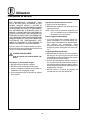
VENTILATION
Ongasmodelsthenecessityforaproperlyde-
signed and installed ventilation system cannot be
over emphasized. This system a llows the oven to
function properly while removing unwanted va-
pors and products of combustion from the operat-
ing area.
This oven must be vented with a properly de -
signed mechanically driven exhaust hood. The
hood should be sized to completely cover the
equipment plus an overhang of at least 6” (15cm)
on all sides not adjacent to a w a ll. The distance
from the floor to the lower edge of the hood should
not exceed 7’ (2.1m). The capacity of the hood
should be sized appropriately and provisions
should be made for adequate makeup air.
U.S. and Canadian installations
Refer to your local ventilation codes. In the ab-
sence of local codes, refer to the National ventila-
tion code titled, “Standard for the Installation of
Equipment for the Removal of Smoke and Grease
Laden Vapors from Commercial Cooking Equip-
ment”, NFPA-96-Latest Edition.
General export and Australian installations
Installation must conform with Local and National
installation standards. Local installation codes
and/or requirements may vary. If you have any
questions regarding the proper installation and/or
operation of your B lodgett oven, please contact
your local distributor. If you do not have a local dis-
tributor, please call the Blodgett Oven Company at
0011-802-860-3700.
WARNING:
Failure to properly vent the oven can be
hazardous to the health of the operator
and may result in operational problems,
unsatisfactory baking and possible dam-
age to the equipment.
Damage sustained as a directresult of im-
proper ventilation will not be covered by
the Manufacturer’s warranty.

Installation
6
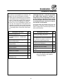
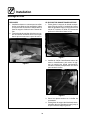
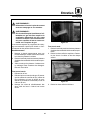
Oven Assembly
OVEN SUPPORTS AND CASTERS
1. Bolt the supports to the oven with 3/8-16 hex
head bolts.
NOTE: Install the locking casters on the front
of the oven.
2. Carefully place the oven onto casters. Have
several persons lift the oven off the pallet and
set it onto t he casters.
3. Engage the brakes on the front casters.
Figure 3
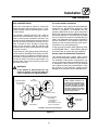
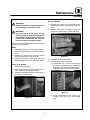
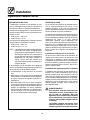
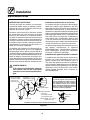
RETURN AIR DIVERTERS
1. Lift the front end of a diverter and slide the end
clips up a nd behind the oven’s rear wall.
2. Low er the front end and slide the diverter into
place. Be certain that the outer edge of t he div-
erter lines up with the cutout in the oven’s rear
wall. A stud on the rear wall acts as a stop to
ensure proper alignment.
Figure 4
Figure 5

Installation
7
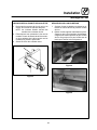
Oven Assembly
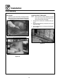
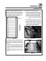
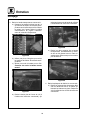
NOZZLES
1. Install the nozzles from the center of the oven
working towards the end. Make sure the bot-
tom of the nozzle fits into t he slot in the nozzle
supportlocatedatthefrontoftheoven.
2. Secure the nozzle hold-down strip across the
inside front of the oven using the existing
screws located on the oven wall.
Figure 6
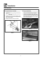
CONVEYOR BELT SUPPORTS
1. Slide the left conveyor support (with sprocket
on the end of the shaft) into the support tracks.
The sprocket must be inside the control box
after being pushed into the oven.
Figure 7
2. Install the drive chain around the drive motor
and the sprocket on the conveyor support.
Push the support back to tighten the chain.
Figure 8
3. Tighten the four bolts on the control box.
4. Slide the right conveyor support into the sup-
port tracks until it touches the left stop.

Installation
8
Oven Assembly
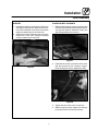
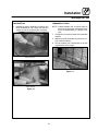
CONVEYOR BELT
The belt has loops on both ends. These loops
must ride backwa rd on the conveyor s upport. Also
note that the belt has a top and bottom. Refer to
Figure 9.
Belt Top
Direction of
Conveyor Travel
Figure 9
NOTE: Unless specified otherwise, conveyor trav-
el is factory set for left to right operation
when facing the front of the oven. If a direc-
tion change is required, the polarity of the
drive motor must be reversed. To reverse
the motor polarity, interchange the black
and white motor leads at the D.C. control-
ler located in the control panel. In addition,
the conveyor belt must be installed from
theleftsideoftheoven.
1. Thread wire belt starting from the right hand
side ofthe oven, lower levelfirst. Unrollthe belt
as shown in Figure 10, otherwise the belt will
be upside down. Leave about one foot hang-
ing out on the left side
NOTE: If belt travel is from left to right, thread
wire belt starting from left side of oven.
2. Take the remainder of the belt, loop it around
the right shaft. Push through on the upper lev-
el.
Figure 10
Figure 11

Installation
9
Oven Assembly
3. The two ends of the belt should be approxi-
mately 6 -9 inches past the left shaft on the up-
per level of the belt support. Right shaft if right
to left travel is required.
4. Install inner master links. See Figure 12 and
Figure 13.
Upside-down
Proper
Position
Figure 12
Figure 13
5. Install the outer master links. See Figure 14
and Figure 15
NOTE: The extra piece of wire belt can be used to
make additional master links in the event
original links are lost or damaged.
Figure 14
Figure 15

Installation
10
Oven Assembly
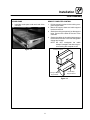
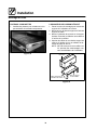
END PLUGS
1. Install the upper and lower end plugs at both
ends of the oven. Secure the upper end plugs
with two wing nuts on the bottom of each plug.
Upper End Plug
Lower End Plug
Figure 16
CONVEYOR BELT TENSIONER
NOTE: Each tensioner installs between the idle
end of the conveyor (the side opposite the
drive) and the lower end plug.
1. Compress the tensioner assembly spring by
hand.
2. Engage the tensioner pin with the hole in the
low er end plug.
3. Lift to engage the pin on the opposite side with
the conveyor.
Figure 17

Installation
11
Oven Assembly
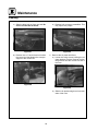
CRUMB PANS
1. Install the crumb pans under each end of the
conveyor.
Figure 18
REMOTE COMPUTER CONTROL
1. Drill t he mounting holes for the cooking com-
puter support base.
2. Mount the support base and cable support
bracket to the wall.
3. Stack the cooking computer(s) on the support
base. Connect the cables at the rear of the
controller.
4. Secure the cables to the cable clamp support
bracket and to the rear of theoven usingcable
clamps and screws.
NOTE: DO NOT overtighten the cable
clamps. Damage to the wires may oc-
cure causing the computer to fail.
Cable Clamp
Support Bracket
Cooking Computer
Support Base
Cooking Computer
Figure 19

Installation
12
Utility Connections --- Standards and Codes
THE INSTALLATION INSTRUCTIONS CON-
TAINED HEREIN ARE FOR THE USE OF QUALI-
FIED INSTALLATIONAND SERVICE PERSONNEL
ONLY. INSTALLA TION OR SERVICE BY OTHER
THAN QUALIFIED PERSONNEL MAY RESULT IN
DAMAGE TO THE OVEN AND/OR INJURY TO
THE OPERATOR.
Qualified installation personnel are individuals, a
firm, a corporation, or a company which either in
person or through a representative are engaged
in, and responsible for:
D
the installation or replacement of gas piping
and the connection, installation, repair or serv-
icing of equipment.
D
the installation of electrical wiring from the elec-
tric meter, main control box or service outlet to
the electric appliance.
Qualified installation personnel must be experi -
enced in such w ork, familiar with all precautions
required, and have compliedwith allrequirements
of state or local authorities having jurisdiction.
U.S. and Canadian installations
Installation must conform with local codes, or in
the absence of local codes, with the National Fuel
Gas Code, NFPA54/ANSI Z223.1---Latest Edition,
the Natural Gas Installation Code CAN/CGA-
B149.1 or the Propane Installation Code, CAN/
CGA-B149.2 as applicable.
All ovens, when installed, must be electrically
grounded in accordance with localcodes, or in t he
absence of local codes, with the National Electrical
Code, ANSI/NFPA 70---Latest Edition and/or Cana-
dian National Electric Code C22.2 as applicable.
General export and Australian installations
Installation must conform with Local and National
installation standards. Local installation codes
and/or requirements may vary. If you have any
questions regarding the proper installation and/or
operation of your B lodgett oven, please contact
your local distributor. If you do not have a local dis-
tributor, please call the Blodgett Oven Company at
0011-802-860-3700.

Installation
13
Gas Connection
GAS PIPING
A properly sized gas supply system is essential for
maximum oven performance. Piping should be
sized to provide a supply of gas sufficient to meet
the maximum demand of all appliances on the line
without loss of pressure at the equipment.
Example:
NOTE: BTU values in the following example are
for natural gas.
You purchase a MT3870 conveyor oven to add to
your existing cook line.
1. Add the BTU rating of your current appliances.
Pitco Fryer 120,000 BTU
6 Burner Range 60,000 BTU
Deck Oven 50,000 B T U
Total 230,000 BTU
2. Add the BTU rating of the new oven to the to -
tal.
Previous Total 230,000 BT U
MT3870 150,000 BTU
New Total 380,000 BTU
3. Measure the distance from the gas meter to
the cook line. This is the pipe length. Let’s say
thepipelengthis20’(6.1m)andthepipesize
is 1” (2.54 cm).
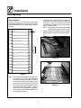
4. Use the appropriate table to determine the to-
tal capacity of your current gas piping.
The tota l capacity for this example is 465,000
BTU. Since the total required gas pressure,
380,000 BTU is less than 465,000 BTU, the
current gas piping will not have to be in-
creased.
NOTE: The BTU capacities given in the tables are
for straight pipe lengths only. Any elbows
or other fittings will decrease pipe capaci-
ties. Contact your local gas supplier if you
have any questions.
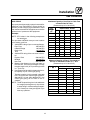
Maximum Capacity of Iron Pipe in Cubic F eet
of Natural Gas Per Hour
(Pressure drop of 0.5 Inch W.C.)
Pipe
L
e
n
g
t
h
Nominal Size, Inches
L
eng
t
h
(ft)
3/4” 1” 1-1/4” 1-1/2” 2”
10 360 680 1400 2100 3950
20 250 465 950 1460 2750
30 200 375 770 1180 2200
40 170 320 660 990 1900
50 151 285 580 900 1680
60 138 260 530 810 1520
70 125 240 490 750 1400
80 118 220 460 690 1300
90 110 205 430 650 1220
100 103 195 400 620 1150
From the National Fuel Gas Code Part 10 Table 10-2
Maximum Capacity of Pipe in Thousands of
BTU/hr of Undiluted P.P. Gas at 11” W.C.
(Pressure drop of 0.5 Inch W.C.)
Pipe Length
(
f
)
Outside Diameter, Inches
p
g
(ft)
3/4” 1” 1-1/2”
10 608 1146 3525
20 418 788 2423
30 336 632 1946
40 287 541 1665
50 255 480 1476
60 231 435 1337
70 215 404 1241
80 198 372 1144
90 187 351 1079
100 175 330 1014
From the National Fuel Gas Code Part 10 Table 10-15

Installation
14
Gas Connection
PRESSURE REGULATION AND TESTING
MT3870 ovens are rate d a t 150,000 BTU/ Hr. (43.9
kW/Hr. ) (158 MJ/Hr.) Each oven has been ad-
justed at the factory to operate with the type of gas
specified on the rating plate attached to the left
side of the control panel.
Each oven is supplied with a regulator to maintain
thepropergaspressure.The regul ator is essen-
tial to the proper operation of the oven and
should not be removed. It is preset to provide the
oven with 3. 5” W.C. (0.87 kPa) for natural gas and
10.0” W.C. (2.50 kPa) for Propane while the flame
is on. The regulator is located on top of the gas
valve, between the manual shutoff and solenoid
valves.
DO NOT INSTALL AN ADDITIONAL REGULATOR
WHERE THE OVEN CONNECTS TO THE GAS
SUPPLY UNLESS THE SUPPLY EXCEEDS THE
MAXIMUM PRESSURE.
NOTE: The maximum gas supply pressure to the
oven is 10.5” W.C. (2.61 kPa) for natural
gas and 13” W.C. (3.2 kPa) for Propane
gas. The minimum gas supply pressure to
the oven is 4.5” W.C. (1.1 kPa) for natural
gas and 11.0” W.C. (2.74 kPa) for Propane
gas.
Installation must conform with local codes, or in
the absence of local codes, with the National Fuel
Gas Code, NFPA54/ANSI Z223.1---Latest Edition,
the Natural Gas Installation Code CAN/CGA-
B149.1 or the Propane Installation Code, CAN/
CGA-B149.2 as applicable.
The oven and its individual shutoff valve must be
disconnected from the gas supply piping system
during any pressure testing of that system at test
pressuresinexcessof1/2psig(3.45kPa).
The oven must be isolated from the gas supply
piping system by closing its individual manual
shutoff valve during any pressure testing of the
gas piping system at test pressures equal or less
than 1/2 psig (3.45kPa).
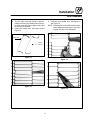
Gas Connection 5” (127 mm)
Gas Connection 6.5” (165 mm)
Figure 20

Installation
15
Gas Connection
GAS HOSE RESTRAINT
If the oven is mounted on casters, a commercial
flexible connector with a minimum of 3/4” (1.9 cm)
inside diameter must be used along with a quick
connect device.
The restraint, supplied with the oven, must be
used to limit the movement of the unit so that no
strain is placed upon the flexible connector. The
restraint should be fastened to the base frame of
the oven as close to the flexible connector as pos-
sible. It should be short enough to prevent any
strain on the connector. With the restraint fully
stretched the connector should be easy to install
and quick connect.
The restraint (ie: heavy gauge cable) should be at-
tached without damaging the building. DO NOT
use the gas piping or electrical conduit for the at-
tachment of the permanent end of the restraint!
Use anchor bolts in concrete or cement block. On
wooden walls, drive hi test wood lag screws into
the studs of the wall.
WARNING!!
If the restraint is disconnected for any
reaso n it must be reconnected when the
oven is returned to its original position.
U.S. and Canadian installations
The connector must comply with the Standard for
Connectors for Movable Gas Appliances, ANSI
Z21.69 or Connectors For Moveable Gas Ap-
pliances CAN/CGA-6.16 and a quick disconnect
device that complies with the Standard for Quick-
Disconnect Devices for Use With Gas Fuel, ANSI
Z21.41 or Quick Disconnect For Use With Gas Fuel
CAN 1-6.9. Adequate means must be provided to
limit the movement of the appliance w ithout de-
pending on the connection and the quick discon-
nect device or its associated piping.
A drip leg must be used at each appliance. Refer
to NFPA54/ANSI Z223.1 - Latest Edition (National
Fuel Gas Code) for proper drip leg installation.
General export and Australian installations
The restraint and quick connect must conform
with Local and National installation standards. Lo-
cal installation codes and/or requirements may
vary. If you have any questions regarding theprop-
er installation and/or operation of your Blodgett
oven, please contact your local distributor. If you
do not have a local distributor, please call the
Blodgett Oven Company at 0011-802-860-3700.
Tighten after
adjustment
(See VIEW A)
VIEW A
Gas
Hose
Socket
Quick Connect
Socket
Plug
IMPORTANT:
Cable restraint should be fas-
tened as close as possible toflex-
ible connector and short enough
to prevent any strain on flexible
connect. At maximum stretch of
shortened restraint the flexible
connector should be easy to in-
stall and quick connect.
Installation of Gas Hose and Restraint
Gas
Supply Line
Attachment Plate
(2 supplied)
1 for wall mount
1 for leg bolt
Note: fastener for wall
mount not supplied
Attachment Plate
(secure with leg
mount bolt)
Figure 21

Installation
16
Electrical Connection
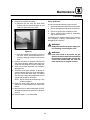
Before making any electrical connections to this
unit, check that the power supply is adequate for
the voltage, amperage, and phase requirements
stated on the rating plate.
NOTE: The rating plate is located on the control
box.
A wiring diagram accompanies this manual and is
also attached inside the control box.
U.S. and Canadian installations
The MT3870 requires a 15 Amp, 60HZ, 1Φ,
208-240VAC, 4 wire service consisting of L1, L2,
neutral and ground. Use 90_CwireandsizetoNa-
tional Electric or local codes.
Single phase units MUST NOT be connected to
the high leg of a t hree phase system. The high leg
refers to a potential of 240 volts between one
phase and neutral. The remaining two legs have
a potential of 120 volts between each phase and
neutral.
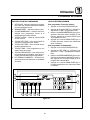
Connect the four wires at the connections box lo-
cated on the lower left side of the control panel.
1. Connect t h e t wo black wires to th e 208-240
volt power source.
2. Connect the white wire to the system neutral.
3. Connect the green w ire to the system ground.
General export and Australian installations
The MT3870 requires a 15 Amp, 50Hz, 1Φ,
220-240 VAC, 3 wire service consisting of L1, neu-
tral and ground. Use 90_Cwireandsizewireac-
cording t o local codes.
WARNING!!
Incorrect single phase wiring will result in
extensive damage to electrical compo-
nents and possible fire in the control pan-
el.
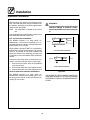
U.S. and Canadian Installations
L1
N
L2
120
120
208-240
OvenSupply
General Export Installations
L1
N
220-240
OvenSupply
Figure 22
THE BLODGETT OVEN COMPANY CANNOT AS-
SUME RESPONSIBILITY FOR LOSS OR DAMAGE
SUFFERED AS A RESULT OF IMPROPER INSTAL-
LA TION.

Operation
17
Safety Information
THE INFORMATION CONT AINED IN THIS SEC-
TION IS PROVIDED FOR THE USE OFQUALIFIED
OPERATING PERSONNEL. QUALIFIED OPERAT-
ING PERSONNEL ARE THOSE WHO HAVE
CAREFULLY READ THE INFORMATION CON-
TAINED IN THIS MANUAL, ARE FAMILIAR WITH
THE FUNCTIONS OF THE OVEN AND/OR HAVE
HAD PREVIOUS EXPERIENCE WITH THE OP-
ERATION OF THE EQUIPMENT DESCRIBED. A D-
HERENCE TO THE PROCEDURES RECOM-
MENDED HEREIN WILL ASSURE THE
ACHIEVEMENT OF OPTIMUM PERFORMANCE
AND LONG, TROUBLE-FREE SERVICE.
Please take the time to read the following safety
and operating instructions. They are the key to the
successful operation of your Blodgett conveyor
oven.
SAFETY TIPS
For your safety read before operating
What to do if you smell gas:
D
DO NOT t ry to light any appliance.
D
DO NOT touch any electrical switches.
D
Use an exterior phone to call your gas supplier
immediately.
D
If you cannot reach your gas supplier, call the
fire department.
What to do in the event of a power failure:
D
Turn all switches to off.
D
DO NOT attempt to operate the oven until the
power is restored.
NOTE: In the event of a shut-down of any kind, al-
low a five (5) minute shut off period before
attempting to restart the oven.
What to do for emergency shut down:
D
For ovens with remote control, the unit is
equipped with an emergency shut down switch.
Should you need to stop the belt, fans, or heat
press the emergency switch. DO NOT use the
emergency switch as a general on/off switch.
General safety tips:
D
DO NOT use tools to turn off the gas control. If
the gas cannot be turned off manually do not try
to repair it. Call a qualified service technician.
D
If the oven needs to be moved for any reason,
the gas must be turned off and disconnected
from the unit before removing the restraint
cable. Reconnect the restraint after the oven
has been returned to its original location.
D
DO NOT remove t he control box cover unless
the oven is unplugged.

Operation
18
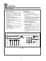
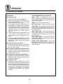
Cooking Computer
CONTROL DESCRIPTION
1. DIGITAL DISPLAY --- displays the time, tem-
perature and controller related information.
2. OVEN ON/OFF --- controls power t o the oven.
3. NUMERIC KEYS --- used to enter numbers in
the programming mode.
4. CLEAR KEY --- clears the display if an error is
made in the programming mode.
5. SET TEMP KEY --- press to view or program
the temperature setpoint.
6. ACT TEMP KEY --- press to view the current
oven temperature.
7. T I M E K E Y --- p res s t o vie w or pr o gr a m th e
cook time.
8. PROG/E NTER KEY --- press to enter and exit
the programming mode and lock in pro-
grammed settings.
9. STATUS LAMPS --- when lit indicate the fan or
burners are operating.
PROGRAMMING
Programming the Cook Time:
1. Press the PROGRAM/ENTER key (8).
2. Press t he TIME key (7). The display reads SET
D
TIME-?.
3. Use the NUMERIC keys (3) to enter the de-
sired cook time. If an error is made, press the
CLEAR key (4) and re-enter the number.
4. Press the PROGRAM/ENTER key (8) to store
the new cook time in the computer’s memory.
Programming the Temperature:
1. Press the PROGRAM/ENTER key (8).
2. Press the SET TEMP key (5). The display
reads SET
D
TEMP-?.
3. Use the NUMERIC keys (3) to enter the de-
sired temperature set point. If an error is
made, press the CLEAR key (4) and re-enter
the number.
4. Press the PROGRAM/ENTER key (8) to store
the new temperature setpoint in the comput-
er’s memory.
1
2
3
45678
9
Figure 23
Page is loading ...
Page is loading ...
Page is loading ...
Page is loading ...
Page is loading ...
Page is loading ...
Page is loading ...
Page is loading ...
Page is loading ...
Page is loading ...
Page is loading ...
Page is loading ...
Page is loading ...
Page is loading ...
Page is loading ...
Page is loading ...
Page is loading ...
Page is loading ...
Page is loading ...
Page is loading ...
Page is loading ...
Page is loading ...
Page is loading ...
Page is loading ...
Page is loading ...
Page is loading ...
Page is loading ...
Page is loading ...
Page is loading ...
Page is loading ...
Page is loading ...
Page is loading ...
Page is loading ...
Page is loading ...
Page is loading ...
Page is loading ...
Page is loading ...
Page is loading ...
-
 1
1
-
 2
2
-
 3
3
-
 4
4
-
 5
5
-
 6
6
-
 7
7
-
 8
8
-
 9
9
-
 10
10
-
 11
11
-
 12
12
-
 13
13
-
 14
14
-
 15
15
-
 16
16
-
 17
17
-
 18
18
-
 19
19
-
 20
20
-
 21
21
-
 22
22
-
 23
23
-
 24
24
-
 25
25
-
 26
26
-
 27
27
-
 28
28
-
 29
29
-
 30
30
-
 31
31
-
 32
32
-
 33
33
-
 34
34
-
 35
35
-
 36
36
-
 37
37
-
 38
38
-
 39
39
-
 40
40
-
 41
41
-
 42
42
-
 43
43
-
 44
44
-
 45
45
-
 46
46
-
 47
47
-
 48
48
-
 49
49
-
 50
50
-
 51
51
-
 52
52
-
 53
53
-
 54
54
-
 55
55
-
 56
56
-
 57
57
-
 58
58
-
 59
59
-
 60
60


Ask a question and I''ll find the answer in the document
Finding information in a document is now easier with AI
in other languages
- français: Blodgett MT3870 spécification
Related papers
-
Blodgett MT3240G Operating instructions
-
Blodgett MT1820E User manual
-
-
-
-
-
-
-
-
Other documents
-
 AMTI Products SHRINK Quick start guide
-
Middleby PS220FS Operating instructions
-
Far Tools BS900 Datasheet
-
-
Star Manufacturing UM1854-NATCE Operating instructions
-
Star Manufacturing UM1854-LPX Operating instructions
-
Casselin CFRPC86 User manual
-
Middleby Marshall Model PS536 User manual
-
-
