Page is loading ...

Emerson.com/FinalControl VCIOM-03190-EN 18/03
Before installation these instructions must be read fully and understood
© 2017 Emerson. All Rights Reserved.
VAREC SERIES 5400A FLAME ARRESTER
InstallatIon, operatIon and maIntenance InstructIons
LIMITATIONS OF SELLER'S LIABILITY
In the event that a court holds that this instruction
manual created some new warranties, the seller's
liability shall be limited to repair or replacement
under the standard warranty clause. In no case
shall the seller's liability exceed that stated as
Limitations of Remedy in the contract between
the seller and buyer.
DISCLAIMER OF WARRANTIES
The contract between the seller and the buyer
states the entire obligation of the seller. The
contents of this instruction manual shall not
become part of or modify any prior or existing
agreement, commitment or relationship
between the seller and buyer. There are no
express or implied warranties set out in this
instruction manual. The only warranties that
apply are those in the existing contract between
the seller and buyer.
Varec Series 5400A flame arresters have not
been tested by under all possible operational
conditions and Emerson does not have all the
data relative to your application. The information
in this instruction manual is not all inclusive and
does not and cannot take into account all unique
situations. Consequently, you should review this
product literature in view of your application. If
you have any further questions, please contact
Emerson for assistance.
SAFETY PRECAUTIONS
Read and understand this instruction manual
before installing, operating or performing
maintenance on Varec 5400A Series flame
arresters. Follow all precautions and warnings
noted herein when installing, operating or
performing maintenance on this equipment.
WARNING
• Flame arresters should be installed upstream
and not more than 15 feet from the ignition
source for use in accordance with UL approval.
• Flame arresters must be isolated from the gas
piping before performing maintenance. All gas
must be blocked and pressure vented safely.
• Flame arresters are not capable of stopping
a flame front in mixtures of air with hydrogen,
acetylene, ethylene oxide or carbon disulfide.
Safety precaution definitions:
CAUTION
Damage to equipment may result if this
precaution is disregarded.
WARNING
Direct injury to personnel or damage to
equipment which can cause injury to personnel
may result if this precaution is not followed.
GENERAL
Varec 5400A flame arresters are designed to
stop the propagation of flame from external
sources. They are used with tank vent and
gas piping systems. These units are installed
where fire protection is required in combination
with pressure relief or shut-off valves in vapor
balancing, recovery or open vent piping systems.
NOTE
Varec flame arresters bearing UL approval are
tested for use on oil storage tanks, installed not
more than 15feet from the open end of the vent pipe
(referenceUL 525). These test conditions may not
represent the actual service conditions or piping
system design. API Publication 2028 states that the
arrester should be tested independently under actual
service conditions before installation.
Use of parts that are not manufactured or
supplied by Emerson voids any Emerson
warranty and relieves Emerson of any
obligation to service theproduct under
warranty. Emerson recommends the use of
only Emerson manufactured or supplied parts
to maintain or service Varec Series 5400A flame
arresters.
This document, or any part of, may not be
reproduced by any means without written
permission of Emerson.
#33-11283 Rev. F

2
VAREC SERIES 5400A FLAME ARRESTER
InstallatIon, operatIon and maIntenance InstructIons
CONSTRUCTION
The standard unit is constructed of heavy cast
housings containing a removable bank assembly
with a spiral wound, crimped core element.
Working pressure rating is 10 psig (69.0 kPa).
For material selection, see the technical
datasheet for the 5400A (VCTDS-00309).
PRACTICAL LIMITATIONS
While flame arresters decrease the possibility
of flame propagation in a system, certain
variables must be evaluated to ensure safety.
The relative fire hazard of flammable mixtures
can be judged by the upper and lower explosive
limits. These limits are expressed as percent by
volume of the gas or vapor in air. The explosive
range is that span of concentrations lying
between the lower and upper limits. The upper
limit is the point at which the mixture is too rich
to burn, i.e. contains too little oxygen to support
combustion. The broader the explosive range
the easier it is to create an air-gas explosive
mixture. Conversely, when the explosive
range is narrow, the chance of developing a
hazardous air-gas mixture decreases.
Table 1 gives the approximate limits of
flammability of some single gases, vapors
and industrial mixtures in air at common
temperatures and at atmospheric pressure.
TABLE 1
Product
Limits in air percent
Product
Limits in air percent
Product
Limits in air percent
Lower Higher Lower Higher Lower Higher
Acetyldehyde 4.1 55.0 Ethyl-alcohol 4.3 19.0 Methyl-alcohol 7.3 36.0
Acetone 3.0 11.0 Ethyl-bromide 6.7 11.3 Methyl-chloride 10.7 17.4
Acetylene 2.5 81.0 Ethyl-chloride 3.8 15.4 Methyl-ethyl-ketone 1.8 10.0
Ammonia 15.0 28.0 Ethyl-ether 1.9 48.0 Methyl-formate 5.9 20.0
Benzene 1.4 7.1 Ethyl-formate 2.7 13.5 Methyl-propyl-ketone 1.5 8.0
Benzine 1.1 - Ethylene 3.1 32.0 Natural gas 3.8 17.0
Blast furnace gas 35.0 74.0 Furfural 2.1 - Nonane 0.8 -
Butadiene 2.0 11.5 Gasoline 1.4 7.6 Octane 1.0 -
Butane 1.9 8.5 Hexane 1.2 7.5 Pentane 1.5 7.8
Butylene 2.0 9.6 Heptane 1.2 6.7 Propane 2.2 9.5
Carbon disulphide 1.25 44.0 Hydrocyanic acid 6.0 41.0 Propyl-alcohol 2.1 13.5
Carbon monoxide 12.5 74.0 Hydrogen 4.0 75.0 Propylene 2.4 10.3
Cyclohexane 1.3 8.0 Hydrogen-sulphide 4.3 45.0 Pyridine 1.8 12.4
Cyclopropane 2.4 10.4 Isobutane 1.8 8.4 Styrene 1.1 6.1
Decane 0.8 5.4 Isopentane 1.4 7.6 Toluene 1.4 6.7
Ethane 3.0 12.5 Isopropyl-alcohol 2.0 12.0 Water gas 7.0 72.0
Ethyl-acetate 2.5 9.0 Methane 5.3 14.0 Xylene 1.0 6.0
Reference: Bureau of Mines Bulletin 503, Limits of Flammability of Gases and Vapors, 1952
WARNING
In all cases where the ratio of upper limit/lower
limit exceeds 10, the use of flame arresters is
not recommended. Also, the presence of any O
2
is dangerous because of the lack of homogeneity
which is possible in gas mixtures. Any surplus of
oxygen provides the potential for rapid explosion.

3
VAREC SERIES 5400A FLAME ARRESTER
InstallatIon, operatIon and maIntenance InstructIons
INSTALLATION
The Varec Series 5400A flame arrester is
designed for vertical application in pipe lines
and on tank covers or roofs. Gas flow may be in
either direction.
1. The cover, roof or piping system must
have the appropriate flange(s) installed
for mating with the flame arrester. Flame
arresters with aluminum housings should
be mated with an ANSI Class 125 F.F.
flange. The 316 stainless steel housing
should be mated with an ANSI Class 150
R.F. flange. The flange must be plumb
and level to ensure proper operation of
the pressure relief valve (when used in
combination with the flame arrester). The
arrester must be located with clearance
allowed for removal of the bank assembly.
2. Remove the flame arrester from the
shipping container or pallet. Remove flange
protectors. Inspect for and remove any
packing or other loose material in the inlet/
outlet chambers of the housing.
3. Place the appropriate full face flange gasket
(by others) on the flange.
CAUTION
If it is necessary to mate an ANSI Class 125 F.F.
flange with an ANSI Class 150 PSI R.F. flange, use
the proper spacer to convert the raised face to a
flat face.
4. Place the arrester on the flange and position
the unit so that the bank assembly can
be extracted readily for inspection and
maintenance, with the housings separated
and jacked open.
5. Install mounting hardware and tighten
uniformly.
6. The flame arrester is now installed and
ready for use.
OPERATION
Flame arresters do not prevent the ignition
of flammable mixtures but do prevent the
propagation of a flame. Varec Series 5400A
flame arresters stop flame propagation by
absorbing and dissipating heat through the
surface area of the spiral wound bank element.
Heat is absorbed as ignited gas attempts
to pass through the small passages within
the bank assembly. This action lowers the
temperature of the gas below its ignition point
and quenches the flame.
MAINTENANCE
Maintenance is the most important factor
in the operation of the flame arrester. The
bank element must be kept clean to prevent a
decrease in gas flow through the system and
loss of heat absorbing efficiency.
WARNING
Failure to maintain the unit properly could result
in reduction of safety and impairment of system
operation.
A regular inspection program is important. The
frequency of inspection is determined by the
application. Consideration should be given to
the amount and nature of water or solids in the
gas and the corrosivity of the process stream.
Generally, the first inspection should be made
30 days after commissioning. Inspections should
continue on a 30 day schedule unless excessive
deposits or accumulation of foreign matter are
found. If so, the frequency of inspections should
be increased. Adjust inspection frequency to
maintain free and unrestricted flow through the
arrester.
WARNING
The flame arrester must be isolated from the
gas piping before performing maintenance. All
gas must be blocked and pressure vented safely.
Ensure that the arrester is cool after a fire, or
wear appropriate protective clothing.
1. Remove nut(s) and tie-rod stud(s) on
the side of the arrester where the bank
assembly will be extracted. Loosen nut(s) on
tie-rod stud(s) on opposite side.
2. Loosen outer nuts on both ends of the two
jackscrews. Alternately turn the four inner
nuts one turn each until the bank assembly
is free for removal from the housings.
Remove the bank assembly.
WARNING
The aluminum bank assembly weighs from 10 to
150 pounds, the steel and 316 SS assemblies are
substantially heavier. Use the appropriate tools and
equipment when handling these units to avoid injury.

4
VAREC SERIES 5400A FLAME ARRESTER
InstallatIon, operatIon and maIntenance InstructIons
GROUP I
Residue type:
Soil, sand, pollen and metallic salts.
Cleaning procedure:
a. Wash the bank assembly with a mild solvent
such as petroleum naptha or commercial
petroleum derived cleaning fluid.
b. Rinse the bank assembly with a solvent that
does not leave an oily film. This is necessary
to avoid collecting foreign matter.
c. Blow out dry particles with compressed air.
d. Wash the bank assembly with hot water.
e. Steam the bank assembly clean.
GROUP II
Residue type:
Metallic oxides and metallic carbonates.
Cleaning procedure:
a.
Wash the bank assembly as described in
Group I, step 1.
b. Soak the entire bank assembly in cold 35%
nitric acid.
CAUTION
Use acid only on aluminum or stainless steel bank
assemblies. Do not use on carbon steel.
NOTE
If residue still remains, place the bank assembly in
boiling 35% nitric acid. Once all residue is removed,
soak the bank assembly in a solution of baking
soda and water (8 oz baking soda to 3 gal water)
to neutralize any remaining acid. Blow dry using
compressed air.
GROUP III
Residue type:
Organic tars, organic gums and sulfur organic
residues.
Cleaning procedure:
a.
Wash the bank assembly as described in
Group I, step 1.
b. Blow out with compressed air.
c. Wash the bank assembly with a strong
solvent such as benzol, xylol, carbon
tetrachloride, acetone, carbon disulphide,
paint thinner (not lacquer) or a mixure of
1
/
3
each of benzol, alcohol and acetone.
5. If residue cannot be removed by the above
procedures, replace with a new bank
assembly.
WARNING
A clogged bank assembly can restrict flow and
reduce its ability to stop flame propagation.
6. Place new gaskets in position, coating each
gasket with a small amount of grease to
hold it in position during replacement of the
bank assembly.
7. Place the bank assembly between the
arrester end housings. Ensure that the
gaskets are in the proper place.
8. Alternately turn the four jackscrew inner
nuts, one turn each, until they are loose and
the housings and bank assembly are seated
properly. Tighten the jackscrew outer nuts
hand tight.
9. Install tie-rod stud(s), install nut(s) hand
tight. Tighten other tie-rod nut(s) hand tight.
Tighten all nuts uniformly around housings.
Reference Figure 1 for torque values.
10. The flame arrester is ready to be placed
back into service.
3. Check the bank core and element for
corrosion or other damage that could cause
an opening for a direct flame path. Replace
with a new bank assembly if necessary.
4. The bank assembly cleaning procedure is
based on the type of residue to be removed.
Determine if its residue type is Group I, II,
orIII. Follow the cleaning procedures for the
selected group.
WARNING
Use all volatile and flammable solvents carefully
to avoid ignition or prolonged breathing. Use
protective clothing and gloves when using acid to
avoid burns from contact with skin.

5
W
W
H
L
5400A2X 2” 14½ (368) 9½ (241) 9⅛ (232) 4 30-35 (41-47)
5400A3X 3” 16½ (419) 11½ (292) 11
3
/
16 (284) 4 40-45 (54-61)
5400A4X 4” 20
5
/
16 (516) 13¼ (337) 15
5
/
8 (397) 6 40-45 (54-61)
5400A6X 6” 21¾ (552) 17¾ (451) 19 (483) 6 95-110 (129-149)
5400A8X 8” 25¾ (654) 22 (559) 23
1
/
4 (591) 6 140-160 (190-217)
5400A0X 10” 30½ (775) 24 (610) 25
1
/
4 (641) 6 220-245 (298-332)
5400A1X 12” 34
9
/
16 (878) 30 (762) 31
1
/
4 (794) 6 220-245 (298-332)
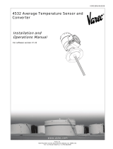
FIGURE 1
5400A Flame arrester
VAREC SERIES 5400A FLAME ARRESTER
InstallatIon, operatIon and maIntenance InstructIons
Ref.
2", 3" and 4" size
Ref.
Ref.
Ref.
Element
Gasket
SIZES AND DIMENSIONS inch (mm)
Model Size(s) L H W
Stud
Qty Torque ft·lbs (Nm)

6
2” 4” 6” 8” 12”10”3”
2” 4” 6” 8” 10”3” 12”
1 2 3 4 5 6 7 8 9 10 20 30 40 50 60 70 80 90 100 200 300 400 500 700 900
600 800 1000
600 800 1000
1 2 3 4 5 6 7 8 9 10 20 30 40 50 60 70 80 90 100 200 300 400 500 700 900
20
15
10
9
8
7
6
5
4
3
2
1
.5
.4
.5
1
2
3
4
5
6
7
8
9
10
15
20
40
30
25
20
15
10
9
8
7
6
5
4
3
2
1
.9
.8
.7
.8
.9
1
2
3
4
5
6
7
8
9
10
15
20
25
30
40
VAREC SERIES 5400A FLAME ARRESTER
InstallatIon, operatIon and maIntenance InstructIons
FLOW CAPACITY - Varec 5400A Series flame arrester
Air flow (CFH) at 22°C and 14.7 PSIA may be determined as follows:
Multiply air flow from chart (SCFH) times the factor 1.0223.
Thousand cubic feet/hour at 60°F and 14.7 psia
Air flow (SCFH)
Vacuum
Ounces per squareinch
Pressure
Ounces per square inch
Inches of water
Inches of water

7
REPLACEMENT PARTS
When ordering replacement parts, specify the flame arrester by model number and pipe size. Identify replacement parts by description and material
as shown in the table below. Include part numbers wherever possible.
Size code 02 03 04 06 08 10 12
Nominal pipe size
2 in. 3 in. 4 in. 6 in. 8 in. 10 in. 12 in.
50 mm 75 mm 100 mm 150 mm 200 mm 250 mm 300 mm
Alum. core housing w/alum. element
[1]
06-02501-011 06-02509-011 06-02517-011 06-11158-011 06-11159-011 06-11160-011 06-11161-011
Alum. core housing w/316 SS element N/A N/A N/A N/A N/A N/A N/A
Steel core housing w/316 SS element N/A N/A N/A N/A N/A N/A N/A
316 SS core housing w/316 SS element
[2]
06-02501-066 06-02509-066 06-02517-066 06-11158-066 06-11159-066 06-11160-066 06-11161-066
Gasket 02-03232-246 02-03232-346 02-03232-446 02-03232-646 02-03232-846 02-03232-046 02-03232-146
NOTES
[1]
For model number 5400A-1
[2]
For model numbers 5400A-2, 5400A-3, 5400A-6
VAREC SERIES 5400A FLAME ARRESTER
InstallatIon, operatIon and maIntenance InstructIons
Neither Emerson, Emerson Automation Solutions, nor any of their affiliated entities assumes responsibility for the selection, use or maintenance of any product.
Responsibility for proper selection, use, and maintenance of any product remains solely with the purchaser and end user.
Varec is a mark owned by one of the companies in the Emerson Automation Solutions business unit of Emerson Electric Co. Emerson Automation Solutions, Emerson
andthe Emerson logo are trademarks and service marks of Emerson Electric Co. All other marks are the property of their respective owners.
The contents of this publication are presented for informational purposes only, and while every effort has been made to ensure their accuracy, they are not to be
construed as warranties or guarantees, express or implied, regarding the products or services described herein or their use or applicability. All sales are governed by
our terms and conditions, which are available upon request. We reserve the right to modify or improve the designs or specifications of such products at any time without
notice.
Emerson.com/FinalControl
/