Entrematic LCU40H Installation guide
- Category
- Gate Opener
- Type
- Installation guide

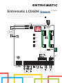
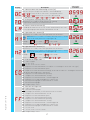
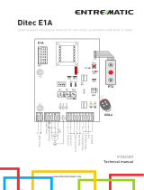
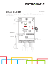
Entrematic LCU40H
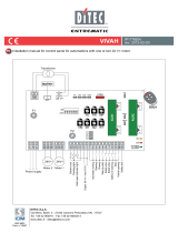
Control panel installation manual for
automations with one or two 24V motors
(Translation of the original instructions)
www.entrematic.com
IP2246EN
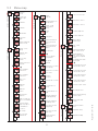
36 35 34 33 32 31
30 2 3 4 9 13
+-LP - +LK 30 5 20 016 018
JR1
J13J14
24V~
COM
A
U
X
2
A
U
X
1
UP
DOWN
TRF
ENTER
ESC
USB
BAT KIT
SCHEDA AD INNESTO
SCHEDA AD INNESTO
F
U
S
E
F1
RDX
6ZENRS
ZENPRS
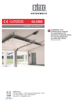
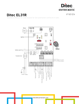
Trasformatore
Alimentazione
Motore 2
24V
Motore 1
Passo-passo
Apertura parziale
Antenna
Chiusura
automatica esterna
Apertura
Chiusura
Stop
Lampada stato
automazione
Lampeggiante
Elettroserratura
AUX1 AUX2
1
30 30
1
-
+
Uscita 24 V
-
+
Uscita 24 V
Arresto di sicurezza
Sicurezza in chiusura
24V
LN
Power supply
Motor 2 Motor 1
Flashing light
Electric lock
Step-by-step
Partial opening
24V output
24V output
Safety stop
Closing safety device
Antenna
Automatic external closing
Opening
Closure
Stop
Automation status
lamp
Transformer

2
IP2246EN - 2017-03-28
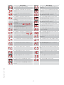
Contents
Subject Page
1. General safety precautions 3
1.1 Safety functions 4
2. EC Declaration of Conformity 4
3. Technical specifications 4
3.1 Applications 4
4. Installation and electrical connections 5
4.1 Maintenance 7
4.2 Standard installation 7
4.3 Standard installation diagram 8
5. Programming 9
5.1 Switching the display ON and OFF 9
5.2 Navigation keys 9
5.3 Menu map 10
6. Quick start-up sequences 12
7. Application examples 14
8. Commands 16
8.1 Inserting the plug-in boards 17
8.2 SOFA1-SOFA2 or GOPAVRS self-controlled safety edge 17
9. Outputs and accessories 18
10. Selections 19
11. Adjustments 20
11.1 Main menu 20
11.2 Second level menu - AT (Automatic Configurations) 21
11.2.1 Selecting the type of automation AT → AS and specific default settings 22
11.3 Second level menu - BC (Basic Configurations) 23
11.3.1 Additional BC level parameters that can be configured (available with AT → AA enabled) 23
11.4 Second level menu - BA (Basic Adjustment) 24
11.4.1 Additional BA level parameters that can be configured (available with AT → AA enabled) 26
11.5 Second level menu - RO (Radio Operations) 28
11.5.1 Additional RO level parameters that can be configured (available with AT → AA enabled) 29
11.6 Second level menu - SF (Special Functions) 30
11.6.1 Additional SF level parameters that can be configured (available with AT → AA enabled) 31
11.7 Second level menu - CC (Cycle Counter) 32
11.7.1 Additional CC level parameters that can be configured (available with AT → AA enabled) 33
11.8 Second level menu - EM (Energy Management) 33
11.8.1 Additional EM level parameters that can be configured (available with AT → AA enabled) 34
11.9 Second level menu - AP (Advanced Parameters) 34
11.9.1 Additional AP level parameters that can be configured (available with AT → AA enabled) 36
12. Diagnostics 38
13. Signals visualised on the display 40
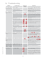
14. Troubleshooting 45
Key
i
This symbol indicates useful information for the correct functioning of the product.
Factory settings
This symbol indicates instructions or notes regarding safety, to which special atten-
tion must be paid.

3
IP2246EN - 2017-03-28
This installation manual is intended for qualified personnel only.
Installation, electrical connections and adjustments must be performed in accordance
with Good Working Methods and in compliance with the present standards.
This product must only be used for the specific purpose for which it was designed.
Any other use is to be considered improper and therefore dangerous. The manufac-
turer cannot be held responsible for any damage caused by improper, incorrect or
unreasonable use.
Read the instructions carefully before installing the product. Incorrect installation
could be dangerous.
The packaging materials (plastic, polystyrene, etc.) should not be discarded in
the environment or left within reach of children, as they are a potential source
of danger.
Before installing the product, make sure it is in perfect condition.
Do not install the product in explosive areas and atmospheres: the presence of in-
flammable gas or fumes represents a serious safety hazard.
The safety devices (photocells, safety edges, emergency stops, etc.) must be
installed taking into account the applicable laws and directives, Good Working
Methods, installation premises, system operating logic and the forces developed by
the automation.
Before connecting the power supply, make sure the plate data correspond to those of
the mains power supply. An omnipolar disconnection switch with a contact opening
distance of at least 3 mm must be fitted on the mains supply.
Check that there is an adequate residual current circuit breaker and a suitable
overcurrent cut-out upstream of the electrical installation in accordance with Good
Working Methods and with the laws in force.
When requested, connect the automation to an effective earthing system that complies
with current safety standards.
During installation, maintenance and repair operations, cut off the power supply
before opening the cover to access the electrical parts.
The electronic parts must be handled using earthed antistatic conductive arms. The
manufacturer of the motorisation device declines all responsibility if component parts
not compatible with safe and correct operation are fitted.
Only use original spare parts when repairing or replacing products.
1. General safety precautions
Failure to observe the information given in this manual may lead to personal
injury or damage to the equipment.
Keep these instructions for future reference

4
IP2246EN - 2017-03-28
Entrematic Group AB declares that the Entrematic LCU40H control panel complies with the fun-
damental requisites and other relevant requirements laid down by the following EC directives:
EMC Directive 2014/30/EU;
Low Voltage Directive 2014/35/EU;
RED Directive 2014/53/EU.
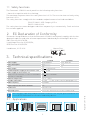
L a n d s k r o n a , 0 1 - 0 7 - 2 0 1 6 M a t t e o F i n o
( P r e s i d e n t & C E O )
2. EC Declaration of Conformity
3. Technical specifications
i
NB: the given operating and performance features can only be guaranteed with the
use of DITEC Entrematic accessories and safety devices.
3.1 Applications
1.1 Safety functions
The Entrematic LCU40H control panel has the following safety functions:
- obstacle recognition with force limiting;
The maximum response time of the safety functions is 0.5 s. The reaction time to a faulty safety
function is 0.5 s.
The safety functions comply with the standards and performance level indicated below:
EN ISO 13849-1:2015 Category 2 PL=c
EN ISO 13849-2:2012
The safety function cannot be bypassed either temporarily or automatically. Fault exclusion
has not been applied.
LCU40H LCU40HJ
Power supply 230 V~ 50/60 Hz 120 V~ 50/60 Hz
Power absorption 0,6 A 1,2 A
Fuse F2 A 4 A
Motor output 24 V 12 A max (X 2)
Permanent power supply to accessories 0-30 24 V 0,15 A
Power supply to accessories 0-1
(in any case, the total of accessories 0-30 and 0-1
must not exceed 0.5A).
24 V 0,5 A continuous
Ambient temperature -20 °C - +55 °C
Storable radio codes 100 / 200 see RO → MU → 20/10 (paragraph 11.6)
Radio frequency 433,92 MHz
Degree of protection of the container IP55
Product size 238 x 357 x 120
Operating cycles Refer to the characteristics of the actuator used.

5
IP2246EN - 2017-03-28
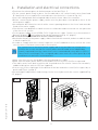
• Perforate the relevant points in the bottom part of the box (Fig. 4.1).
• Fix the control panel firmly in place. You are advised to use convex head screws (max head
Ø 10mm) with a cross imprint (the centre distance for the holes is shown in Fig. 4.2).
• Insert the cable glands and corrugated tubes from the lower side of the container.
• Before connecting the power supply, make sure the plate data correspond to those of the
mains power supply.
• An omnipolar disconnection switch with a contact opening distance of at least 3mm must be
fitted on the mains supply.
• Check there is an adequate residual current circuit breaker and overcurrent cut-out upstream
of the electrical system.
• For the power supply, use a H05RN-F 3G1.5 type electric cable. Connect it to the terminals L
(brown), N (blue), (yellow/green) inside the automation (Fig. 4.3, page 6).
NB: the maximum permitted wire section is AWG14 (2mm2).
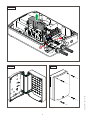
• Unsheathe the part of the power supply cable in line with the terminal, and use a cable fastener
to hold it in place [A].
• In order to comply with the essential requisites of the Standards in force, reclose the cover
once the wires have been connected to the terminal.
• Make sure there are no sharp edges that may damage the cables.
• Make sure the mains power wires (230V) and the accessory wires (24V) are separated.
• The cables must have dual insulation, be sheathed near the relative connection terminals,
and be held in place with ties [B] (not supplied).
• If necessary, fit the clip hinges on the bottom of the box and on the cover (left or right side, as
preferred) (Fig. 4.4, page 6).
After making the adjustments and settings, fix the cover in place with the screws supplied (Fig.
4.5, page 6).
The connections to the mains power supply and to any possible low voltage wires
(230V) in the section outside the control panel must be made on an independent
channel separated from the connections to the command and safety devices (SELV =
Safety Extra Low Voltage). The corrugated tubes must enter the control panel by a few
centimetres via the holes on the base box.
4. Installation and electrical connections
215
295
Fig. 4.2
Fig. 4.1
i

6
IP2246EN - 2017-03-28
A
B
Fig. 4.5
Fig. 4.3
Fig. 4.4

7
IP2246EN - 2017-03-28
1
5
4
6
A
32
5
5
4
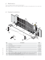
4.2 Standard installation
4.1 Maintenance
Ref. Description Cable
1Transmitter /
2Flashing light 2 x 1mm²
Antenna (integrated in the flashing light) coaxial 50 Ω
3Key selector switch 4 x 0.5mm²
Digital combination wireless keypad /
4Actuator 2 x 1.5mm²
Actuator with limit switch 3 x 1.5mm²
5Photocells 4 x 0.5mm²
6Control panel 3G x 1.5mm²
A
Connect the power supply to a type-approved omnipolar switch, with a contact opening
distance of at least 3mm (not supplied).
Connection to the mains must be via an independent channel, separated from the
connections to the command and safety devices.
The control panel needs no special maintenance.
Make regular checks to ensure the good condition of the box seals and the electrical connections.

8
IP2246EN - 2017-03-28
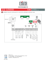
4.3 Standard installation diagram
TX
01
TX
01
C
NO
NC
Power supply
14
0
RX
01
RX
01
36 35 34 33 32 31 +-LP - +LK 30 5 20 016 018
LN
LCU40H

9
IP2246EN - 2017-03-28
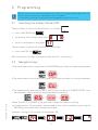
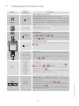
The procedure to switch on the display is as follows:
• press the ENTER key
• the display functioning check starts
• the first level menu is displayed
The procedure to switch off the display is as follows:
• press the ESC key
NB: the display switches off automatically after 60 s of inactivity.
• The simultaneous pressing of the ↑ and ENTER keys produces an opening command.
• The simultaneous pressing of the ↓and ENTER keys produces a closing command.
• The simultaneous pressing of the ↑ and ↓ keys produces a POWER RESET com-
mand (power supply interruption and automation restart).
• Keep the UP ↑ or DOWN ↓ key pressed to begin fast menu scrolling.
• In some menus, the parameter measurement unit can be viewed by pressing the
ENTER key once the value has been displayed.
Example: setting of 10 seconds for parameter OB.
5. Programming
5.1 Switching the display ON and OFF
i
NB: pressure on the keys may be quick (less than 2 s) or prolonged (longer than 2 s).
Unless specified otherwise, quick pressure is intended.
To confirm the setting of a parameter, prolonged pressing is necessary.
5.2 Navigation keys

10
IP2246EN - 2017-03-28
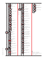
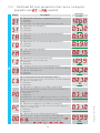
5.3 Menu map
Automation
selection
Automatic closing
time after partial
opening
Adjustment of thrust on
obstacles and current
- motor 1
Setting of memory opening
via remote control
Setting of radio coded
messages
Adjustment of thrust on
obstacles and current
- motor 2
Maximum number of
remote controls that can
be stored in the integrated
memory
Menu navigation via remote
control keypad
Selection of function CH1 of
the stored remote control
Selection of function CH2 of
the stored remote control
Selection of function CH3 of
the stored remote control
Selection of function CH4 of
the stored remote control
Deletion of a remote control
Total memory deletion
Control panel firmware
version
Configuration storage
Configuration loading
Selection of the
number of gate
wings
Reset general
settings
Activation of advanced
parameters menu
Opening
speed
Closing speed
Motor delay time
Function of output -LK+
Function of output +LP-
Indicator light for
automation open
Remote control
storage
Visualisation of number of
remote controls stored
Obstacle recognition
time adjustment
Start-up time
adjustment
Adjustment of acceleration
time on opening
Adjustment of acceleration
time on closure
Adjustment of deceleration
time
Deceleration time on
opening
Deceleration distance on
closing
Adjustment of approach
speed during opening
Adjustment of approach
speed during closure
Obstacle detection limit
during opening
Obstacle detection limit
during closure
Delay time of motor 2
during opening
Electric lock release time
Operation time - motor 1
Operation time - motor 2
Initial move-
ment speed
Residential 0
Residential 1
Condominium 0
Automatic closure
enabling
Automation status
at switch-on
Reversal safety
operation
Activation of anti-freeze
system NIO
Contact command
operation 30-5
Contact command
operation 30-3
Radio receiver
operation
AUX1 board
operation
AUX2 board
operation
Start-up at maxi-
mum power
Setting of step-by-step
sequence via command
30-5
Duration of STOP in
step-by-step sequence
via command 30-5
Check on me-
chanical stops
Motor circuit with
automation idle
Automatic
closing time
Partial opening measure-
ment adjustment
Automatic configurations
Standard settings
Standard adjustments
Wireless operations
Special functions
*
*
*

11
IP2246EN - 2017-03-28
Password setting
Password
insertion
Deletion of user settings
Loading of last configu-
ration set
Selection of device
connected to terminals
1-6 and 1-8
Switch-on time for
independently commanded
courtesy light
Fixed partial opening
Alarm counter
Alarm log
Alarm reset
Firmware update
Display visualisation
mode
Courtesy light switch-on
time
Duration of disengagement
after edge intervention
Duration of disengagement
on stop during opening
Duration of disengagement on
stop during closure
Selection of type of
obstacle
Stroke estimate
correction
NIO intervention tempera-
ture and automatic ramps
Visualisation of internal
panel temperature
Automatic ramp ad-
justment
Setting pre-flashing time
on opening
Adjustment of approach
speed during closure
Renew automatic closing
time after safety device
release
Learning speed setting
Selection of operating
mode for device connected
to terminals 1-6
Writing of alarms on
micro SD card
Safe removal of micro
SD card
Motor current display
Enabling of diagnostics
Total number of
operations
Partial number of
operations
Power supply hours
Power supply hours
via battery
Maintenance alarm
setting
Visualisation of mainte-
nance alarm mode
Reset of partial operations
counter
Power supply via solar
panels
Energy-saving mode
Batteries almost flat
Voltage threshold for indi-
cating when the batteries
are almost flat
Battery mode
Selection of opening
limit switch mode
Selection of closure
limit switch mode
Selection of device con-
nected to terminals 1-6
Selection of device con-
nected to terminals 1-8
Configuration of input 30-9
Cycle counters
Energy management
Advanced parameters
*
*
*
*
*
Additional configurable
parameters available with AT
→ AA is enabled.

12
IP2246EN - 2017-03-28
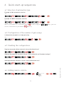
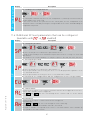
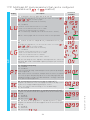
6. Quick start-up sequences
6.1 Selection of automation type
x2 s
Example of Obbi automation selection
x2 s
Example of PWR25 automation selection
NB: if no automation is selected (alarm active) using the keys, you can
access the values of parameter directly.
Set
Set
Set
Configuration example for a single gate wing
6.2 Configuration of the number of gate wings
6.4 Adding remote controls
6.3 Enabling the configurations
x1, x2, ...
Step-by-step mode without automatic closure (residential use)
Step-by-step mode with automatic closure 1 min (residential use) [standard settings]
Opening mode with automatic closure 1 min (condominium use)

13
IP2246EN - 2017-03-28
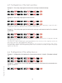
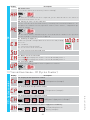
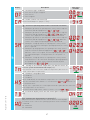
6.5 Configuration of the limit switches
6.6 Configuration of the safety devices
Set
Set
Set
Set
Set
With these settings, if an obstacle is detected while the gate wing is opening, it stops with a dis-
engagement operation; during closure, the gate wing reopens).
With these settings, the gate wing stops against its respective mechanical closing end stop and
the opening limit switch.
If an obstacle is detected during the opening and before the activation of the stop limit switch, the
gate wing stops with a disengagement operation.
If an obstacle is detected during closure and before the activation of the proximity limit switch,
the gate wing reopens; once the proximity limit switch has been activated, the gate wing stops
against the obstacle.
Example 1 - Door wing stops against mechanical end stops (standard setting)
Example 1 - Configuration of the photocells connected to terminals 1-8 and 1-6 [standard settings]
Example 2 - Configuration of the safety edge with safety test simultaneously connected to ter-
minals 1-6 and 1-8
Example 2 - Door wing stops against limit switches
Example 3 - Door wing stops against mechanical end stops and reverses motion if an obstacle
is detected

14
IP2246EN - 2017-03-28
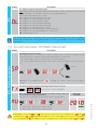
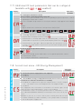
7. Application examples
24V24V
Motore 1Motore 2
12
363534 3332 31
24V24V
Motore 1Motore 2
12
3635 34 3332 31
Fig. 7.1 Fig. 7.2
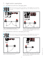
7.1 Automations with two swinging gates
7.2 Automations with one swinging gate wing
When the Entrematic LCU40H control panel is used in applications for automa-
tions with one swinging gate wing, the following connections can be made:
24V=
1
Motore 1
3332 31
Fig. 7.3
1
24V=
Motore 1
3332 31
Fig. 7.4
When the Entrematic LCU40H control panel is used in applications for automa-
tions with two overlapping swinging gate wings, the following connections can
be made:
(Fig. 7.2) Installation with mechanical end
stop for closure, and with the use of elec-
tric limit switches (stop during opening and
proximity during closure).
(Fig. 7.1) Installation with mechanical end
stops for opening and closure, and
without the use of electric limit switches.
(Fig. 7.3) Installation with mechanical end
stops for opening and closure, and without
the use of electric limit switches.
(Fig. 7.4) Installation with mechanical end
stop for closure, and with the use of elec-
tric limit switches (stop during opening and
proximity during closure).
Motor 1
Motor 1
Motor 2 Motor 1
Motor 1
Motor 2

15
IP2246EN - 2017-03-28
24V=24V=
A C
1N4007
363534 3332 31
MotoreMotore 12
24V=24V=
A C
1N4007
363534 3332 31
MotoreMotore 12
24V=24V=
363534 3332 31
MotoreMotore
12
24V=24V=
A C
1N4007
363534 3332 31
MotoreMotore 12
Fig. 7.5 Fig. 7.6
Fig. 7.7 Fig. 7.8
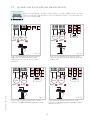
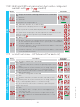
7.3 Up-and-over doors with two parallel motors
When the Entrematic LCU40H control panel is used in applications for auto-
mations with up-and-over doors with two parallel motors, the following con-
nections can be made:
(Fig. 7.5) Installation with mechanical
end stops for opening and closure,
and without the use of electric limit
switches.
[Fig. 7.6] Installation with electric limit
switches for deceleration during opening
and closure.
[Fig. 7.7] Installation with electric limit
switches (stop during opening and closure). [Fig. 7.8] Installation with electric limit
switches (stop during opening and proximity
during closure).
Motor Motor Motor Motor
Motor Motor
Motor Motor

16
IP2246EN - 2017-03-28
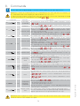
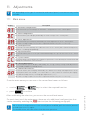
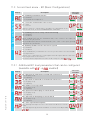
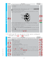
8. Commands
Command Function Description
30 2 NO AUTOMATIC
CLOSURE
The permanent closure of the contact enables automatic closure
if →
30 3 NO
OPENING When selecting → → , the closure of the contact acti-
vates an opening operation.
STEP-BY-STEP
When selecting → → , the closure of the contact
activates a sequential opening or closing operation: open-
ing-stop-closing-opening.
The “opening-stop-closing-opening” sequence can be changed
to “opening-stop-closing-stop-opening” by selecting → .
30 4 NO CLOSURE The closure of the contact activates a closing operation.
30 5 NO
STEP-BY-STEP
When selecting → → , the closure of the contact
activates a sequential opening or closing operation: open-
ing-stop-closing-opening.
WARNING: if automatic closure is enabled, the duration of the
stop can be defined by selecting → .
The “opening-stop-closing-opening” sequence can be changed
to “opening-stop-closing-stop-opening” by selecting → .
OPENING When selecting → → , the closure of the contact acti-
vates an opening operation.
1 6 NC SAFETY STOP
The opening of the safety contact stops and prevents any movement.
NB: to set different safety contact functions, see the →
parameter settings.
1 8 NC
CLOSING
SAFETY DE-
VICE
The opening of the safety contact triggers a reversal of the move-
ment (reopening) during the closing operation.
When selecting → → , the opening of the contact pre-
vents any operation when the automation is idle.
When selecting → → , the opening of the contact only
prevents closure when the automation is idle.
1 6
8 NC
CLOSING/
OPENING
SAFETY DE-
VICE
The opening of the safety contact stops and prevents any move-
ment.
NB: operation corresponds to that of contact 1-6 with →
→ .
30 9 NC STOP
The opening of the safety contact causes the current operation to
stop.
If - = ,automatic closure is disabled when contact 30-9
recloses.
If - = ,automatic closure remains enabled when contact
30-9 recloses.
30 9 NO
"OPERATOR
PRESENT"
COMMAND
When selecting → → , the opening of contact 30-9 ena-
bles the "operator present" function:
- opening with operator present 30-3
- closure with operator present 30-4
NB: any safety devices, automatic closure and plug-in board in the
AUX housing are all disabled.
30 20 NO PARTIAL OPEN-
ING
The closure of the contact activates a partial opening operation.
Once the automation stops, the partial opening control performs the
opposite operation to the one performed before the stop.
WARNING: make a jumper for all NC contacts if not used, or deactivate them via the relative menu.
Terminals with the same number are equal.
WARNING: terminal 30 (common positive for commands) has the same functions as terminal 1, so
the commands visible on the display are indicated with 1-5, 1-3, 1-4, etc.
It is different from terminal 1, however, because of the maximum current that can be dispensed and
it is also active when the control panel is in standby → .
i
You are advised to read paragraph 11 for all the details about the possible adjustments.

17
IP2246EN - 2017-03-28
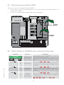
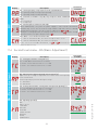
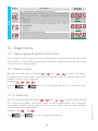
8.1 Inserting plug-in boards (AUX)
To access the slots for plug-in boards (AUX):
• If you want to insert just one board, cut the control panel cover and remove it as
shown in the figure.
• If both slots are needed, remove the cover completely.
8.2 SOFA1-SOFA2 or GOPAVRS self-controlled safety edge
Command Function Description
GOPAV
SOFA1-SOFA2
SAFETY TEST
Insert the SOFA1-SOFA2 or GOPAVRS device in the slot
for plug-in boards AUX1 or AUX2.
If the test fails, an alarm message appears on the
display.
1 6
NC SAFETY STOP
When selecting → → , connect the output
contact of the safety device to terminals 1-6 on the con-
trol panel (in series with the photocell output contact,
if installed).
1 8
NC CLOSING SAFE-
TY DEVICE
When selecting → → , connect the output
contact of the safety device to terminals 1-8 on the con-
trol panel (in series with the photocell output contact,
if installed).
1 6
8 NC
CLOSING/
OPENING
SAFETY DEVICE
When selecting → → , connect the output
contact of the safety device to terminals 1-6-8 on the
control panel (in series with the photocell output con-
tact, if installed).
If → , and cannot be or .
36 35 34 33 32 31 +-LP - +LK 30 5 20 0 1 6 0 1 8
30 2 3 4 9 13
AUX1
AUX2

18
IP2246EN - 2017-03-28
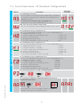
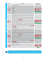
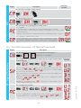
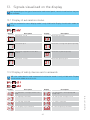
9. Outputs and accessories
Output Value of
accessories Description
0
-
1
+
24V / 0.5 A
Power supply to accessories
Output for power supply to external accessories.
NB: the maximum absorption of 0.3A corresponds to the sum
of all terminals 1.
The "gate open" indicator light (30-13) is not calculated in the
0.3A indicated above. The maximum value to be considered
is 3W.
GOL148REA
If the GOL868R4 radio receiver is used (868.35 MHz), connect the
supplied antenna wire (90mm).
+LP- LAMPH
24V / 25W
Flashing light
The pre-flashing settings can be selected from the third level
menu → and/or → .
To modify the operating mode of the LP output, refer to the
selection → .
30 2 3 4 9 13
24V / 3W
Automation status lamp
For the operating mode of output 30-13, refer to the selection
→ .
-+LK
12V~ / 15W
Electric lock
It is activated when the operation begins with the automation
closed.
To modify the operating mode of the LK output, refer to the
selection → .
AUX 1
AUX 2
SOFA1-SOFA2
GOPAVRS
LAN4S
LAB9
BIXLR12
BIXLR22
GOL868R4
BIXLR42
LAN7S
The control panel has two slots for plug-in command and
safety boards.
The action of the control board can be selected using →
for AUX1 and → for AUX2.
When using slot-in radio boards, remove the RDX module.
The display will show .
WARNING: the plug-in board must be inserted and removed
with the power supply disconnected.
RDX 6ZENRS
ZENPRS
The control panel is fitted with a housing for modules of the
6ZENRS radio receiver type (433.92 MHz).
Can be replaced with a radio receiver module of the ZENPRS
type (868.35 MHz).
The operating mode is selected via → .
When using slot-in radio boards, remove the RDX module.
The display will show .
WARNING: the modules must be inserted and removed with the
power supply disconnected.

19
IP2246EN - 2017-03-28
Jumper Description OFF ON
JR1 Display mode selection Display mode.
Only the values and pa-
rameters present can be
displayed.
Maintenance mode.
Only the values and pa-
rameters present can be
displayed and modified.
Activated maintenance
mode is indicated by the
permanent switching on of
the right-hand point on the
display.
Jumper Description 130 130
AUX1 Selection of power supply - auxil-
iary board 1
AUX1 powered from 0-1. AUX1 powered from 0-30.
AUX2 Selection of power supply - auxil-
iary board 2
AUX2 powered from 0-1. AUX2 powered from 0-30.
Output Value of
accessories Description
USB
The control panel is fitted with a USB input for connecting to
a PC in order to update firmware files using AMIGO software
(with a Standard-A plug, or Micro-B plug USB cable).
MicroSD
The control panel manages microSD cards for updating the
firmware and for diagnostics and configuration storage/re-
covery via the in commands → and → .
NB: use a microSD with a maximum capacity no greater than
16 Gb.
COM
BIXM R2
COM - This allows the functioning configurations to be saved
using the function → .
The saved configurations can be recalled using the function
→ .
COM - The storage module allows the remote controls to be
stored. If the control panel is replaced, the storage module being
used can be inserted in the new control panel.
WARNING: the storage module must be inserted and re-
moved with the power supply disconnected, and paying at-
tention to the positioning direction.
BAT
SBU
BAT - Battery-powered operation.
The batteries are kept charged when the power supply is on. If the
power supply is off, the panel is powered by the batteries until the
power is re-establish or until the battery voltage drops below the
safety threshold. The panel turns off in the last case. WARNING:
the batteries must always be connected to the control panel
for charging. Periodically check the efficiency of the batteries.
NB: the operating temperature of the rechargeable batteries is
from +5°C to +40°C. For advanced control of battery-powered
operation, refer to the menu .
10. Jumper setting

20
IP2246EN - 2017-03-28
• use the and keys to select the required function
• press to confirm
After confirming the selection, you access the second level menu.
11.1 Main menu
Display Description
AT - Automatic Configurations.
The menu allows you to manage the automatic configurations of the control panel.
BC - Basic Configurations.
The menu allows you to display and modify the main settings of the control panel.
BA - Basic Adjustments.
The menu allows you to display and modify the main adjustments of the control panel.
NB: some settings require at least three operations before they are set correctly.
RO - Radio Operations.
The menu is used to manage the radio functions of the control panel (alarm management,
diagnostics enabling, FW updating).
SF - Special Functions.
The menu allows you to set the password and manage the special functions in the control
panel.
CC - Cycles Counter.
The menu allows you to display the number of operations carried out by the automation and
manage the maintenance interventions.
EM - Energy Management.
The menu allows you to display and modify the energy saving settings and adjustments
(Green Mode and battery management).
AP - Advanced Parameters.
The menu allows you to display and modify the advanced settings and adjustments of the
control panel (limit switch mode, selection of devices connected to the terminals, disengage-
ment duration adjustments, flashing light adjustments, etc.).
NB: some settings require at least three operations before they are set correctly.
11. Adjustments
For each function of the main menu, there are also additional configurations that
can be viewed by enabling the function (see the following paragraph).
From the main menu you can access the second level menu as follows:
i
i
NB: depending on the type of automation and control panel, some menus may not be
available.
NB: to check if the parameters have actually been modified, quit the relative parame-
ter and then access it again.
The modifications will take effect from the next operation.
Page is loading ...
Page is loading ...
Page is loading ...
Page is loading ...
Page is loading ...
Page is loading ...
Page is loading ...
Page is loading ...
Page is loading ...
Page is loading ...
Page is loading ...
Page is loading ...
Page is loading ...
Page is loading ...
Page is loading ...
Page is loading ...
Page is loading ...
Page is loading ...
Page is loading ...
Page is loading ...
Page is loading ...
Page is loading ...
Page is loading ...
Page is loading ...
Page is loading ...
Page is loading ...
-
 1
1
-
 2
2
-
 3
3
-
 4
4
-
 5
5
-
 6
6
-
 7
7
-
 8
8
-
 9
9
-
 10
10
-
 11
11
-
 12
12
-
 13
13
-
 14
14
-
 15
15
-
 16
16
-
 17
17
-
 18
18
-
 19
19
-
 20
20
-
 21
21
-
 22
22
-
 23
23
-
 24
24
-
 25
25
-
 26
26
-
 27
27
-
 28
28
-
 29
29
-
 30
30
-
 31
31
-
 32
32
-
 33
33
-
 34
34
-
 35
35
-
 36
36
-
 37
37
-
 38
38
-
 39
39
-
 40
40
-
 41
41
-
 42
42
-
 43
43
-
 44
44
-
 45
45
-
 46
46


Entrematic LCU40H Installation guide
- Category
- Gate Opener
- Type
- Installation guide
Ask a question and I''ll find the answer in the document
Finding information in a document is now easier with AI
Related papers

Other documents
-
 DITEC E2H Owner's manual
-
PEDROLLO COD. Z-DPL90073UK User manual
-
 Entre Matic Ditec EL31R User manual
-
 DITEC EL31R Owner's manual
-
 DITEC LOGICM Owner's manual
-
V2 FLEXY2 User manual
-
 Ditec Entrematic CS12E User & Installation Manual
-
 DITEC VIVAH Owner's manual
-
 DITEC DAS107 Technical Manual
-
 DITEC E1T Owner's manual


