Page is loading ...

1102. 6180892_00
ROOF-TOP UNITS R410A - Manual selection, installation and maintenence
RTE
240-400
GB

AERMEC S.p.A.
37040 Bevilacqua (VR) – Italy
Via Roma, 996
Tel. (+39) 0442 633111
www .aermec. com 1115
DICHIARAZIONE DI CONFORMITA’
DECLARATION OF CONFORMITY
DÉCLARATION DE CONFORMITÉ
KONFORMITÄTSERKLÄRUNG
Tipo macchina / Type of unit / Type
de machine / Maschinentyp Condizionatore d'aria tipo Roof-top, Roof-top air conditioning unit
Unité de climatisation Roof-top, Autonome Klimaanlage
Modello / Model / Modèle / Modell
Matricola / Serial No /
Numéro de série / Seriennummer
La macchina è conforme alle disposizioni contenute nelle seguenti direttive: / The unit complies with the
provisions contained in the following directives: / La machine est conforme aux dispositions contenues
dans les directives suivantes: / Das Gerät entspricht den Bestimmungen der folgenden Richtlinien
enthaltenen:
2006/42/CE Direttiva Macchine / Machine Directive / Machine Directive / Maschinenrichtlinie
2006/95/CE Direttiva Bassa Tensione / Low voltage Directive / Basse Tension / Niederspannungsrichtlinie
2004/108/CE Direttiva EMC / EMC Directive / EMC Directive / EMV-Richtlinie
97/23/CE Direttiva PED / PED Directive / PED Directive / PED-Richtlinie
ed è stato sottoposto alla procedura di valutazione A1 con controlli dell’organismo Società Consortile
PASCAL a r.l. (n° 1115) via A. Scarsellini, 13 – 20161 Milano (certificato n° 20 del 10/02/2003)
has been evaluated according to the A1 procedures with controls carried out by PASCAL (n°1115)
company, address A. Scarsellini 13, 20126 Milan (certificate n°20 dated 10/02/2003)
et a été vérifiée selon la procédure A1 par l’organism Società Consortile PASCAL a r.l. (n° 1115) via A.
Scarsellini, 13 – 20161 Milano (certificat n° 20 date 10/02/2003)
wurde überwacht nach Beobachtung Unternehmen PASCAL (n°1115), Adresse A. Scarsellini 13, 20126
Mailand (Zertifikat n°20 von 10/02/2003
Componente / Component / Élément / Komponente Modulo / Module / Module / Modul
Pressostato di alta pressione / Pressure switch / Pressostat / Druckschalter B + D
Valvola di sicurezza / Pressure relief valve / Valve de sécurité / Sicherheitsventil B + D
Compressore / Compressor / Compresseur / Kompressor D1
Ricevitore di liquido / Liquid receiver / Flüssigkeitssammler / Boutilles liquide A
Separatore di liquido / Suction accumulator / Flüssigkeitsabscheider / Boutilles anti-coup A
Filtro deidratatore / Filter / Filter / Filtres A
Rubinetti / Ball valve / kleinventile / Vanes A
Batteria di scambio termico / Coil / Register / Batterie A
La persona autorizzata a costituire il fascicolo tecnico è: / The person authorized to compile the technical
file is: / La personne autorisée à constituer le dossier technique est: / Die Person berechtigt, die
technischen Unterlagen zusammenzustellen:
Giampaolo Cardin via Luppia Alberi,170
Bevilacqua, 25/01/2011 Luigi Zucchi

Index
English
General norm 4
Units identification and description 5
Version cambination 6
Unit configuration 7
Description of components 10
Regulation system 11
Accessories 12
Technical data 14
Operating limits 20
Sound data 20
Cooling capacity and input power 21
Heating capacity and input power 22
Corrective coefficients for different flow rates 23
Total capacities for different relative humidities 23
Performance tables for water heating coils 24
Technical data generator Gxxx 25
List of pressure equipment - Directive PED 97/23 CE 26
Refrigerant circuits 26
Dimensions 28
Nominal dimensions 32
Refrigerant charge 32
Weights 33
Configurations 34
RTE with three-way mixing box 35
RTE with heat recovery unit 35
RTE with heat generators G72 - G92 - G150 kW 37
PR2 remote panel 38
Installing and using the unit 39
Norms covering the use of R410A gas 40
Hydraulic connections - Condensate drain pain 40
Connection aeraulic 41
Joining RTE sections 42
Improper use 43
Electrical wiring 43
Security 44
Unit maintenance 44
Monthly maintenence program 45
Diagnosis and fault solving 46

Manual selection, installation and maintenance 4
Roof-top units - RTE series-
This manual is an integral
part of the documentation
enclosed with the unit.
It must be preserved for
future reference and must
accompany the machine throughout its
life.
The manual defines the purpose for
which the machine has been built and
establishes its correct installation and
the limits of its use.
• This manual provides all the
technical instructions and
instructions for the installation
of this unit and the main accident
prevention regulations.
Read carefully and thoroughly all the
information referred to in this manual.
Pay particular attention to the usage
instructions accompanied by the words
"DANGER" or "WARNING" because, if
not observed, they can cause damage
to the machine and/or property and/or
injury to people.
If any malfunctions are not included
in this manual, contact the local After
Sales Service immediately.
• AERMEC S.p.A. declines all liability
for any damage due to improper
use of the machine or the partial or
superficial reading of the information
contained in this manual.
• Installation and maintenance
must be carried out by trained
and qualified personnel, having
the requirements laid down by
law 46/90 and/or DPR 380/2001
for electric/electronic and air
conditioning installations, with
consequent registration at the
local CHAMBER of COMMERCE.
Otherwise AERMEC S.p.A. decline
all responsibility regarding the safety
of the product.
THE MANUFACTURER DECLINES ALL
LIABILITY FOR DAMAGE TO THINGS
OR INJURY TO PERSONS AND
ANIMALS CAUSED BY THE FAILURE
TO OBSERVE THE INSTRUCTIONS
AND STANDARDS IN THIS MANUAL.
Even though during the design phase of
the RTE unit adequate assessment of the
risks was made, pay ATTENTION to the
pictograms on the machine that helps
the reading the manual by drawing the
reader's attention rapidly to the risk
situations that cannot be avoided or
sufficiently limited by using measures
and technical means of protection.
GENERAL HAZARD SIGNAL
Carefully adhere to all the
indications next to the icon.
Failure to comply with the instructions
may generate hazardous situations
with possible damage to the health
of the operator and user in general.
DANGEROUS ELECTRICAL
VOLTAGE SIGNAL
Carefully adhere to all the
indications next to the icon.
The signal indicates components of the
unit or, in this manual, specifies actions
that could generate electrically-related
risks.
GENERAL PROHIBITION
SIGNAL
Carefully adhere to all the
indications next to the icon that limit
actions in order to guarantee better
operator safety.
IT IS PROHIBITED TO
CLEAN, OIL AND GREASE,
repair or manually adjust
parts in motion.
INFLAMMABLE MATERIAL.
MAIN WARRANTY
CONDITIONS
• The warranty does not include
payment for damage due to the
incorrect installation of the unit by
the installation engineer.
• The warranty does not include
payment for damage due to the
improper use of the unit by the user.
• The manufacturer does not consider
itself liable for accidents to the user
or the installer due to the incorrect
installation or improper use of the
unit.
The warranty is not valid when:
• the services and the repairs have
been carried out by non-authorised
personnel or companies;
• the unit has been repaired or
modified in the past with non OEM
spare parts;
• the unit has not been adequately
maintained;
• if the instructions described in this
manual have not been followed;
• if non-authorised modifications have
been made.
Note:
The Manufacturer reserves the right at
all times to make any modification for
the improvement of its product and is
not obliged to add these modification
to machines of previous manufacture
that have already been delivered or are
being built.
The warranty conditions are any
subject to the general sales conditions
at the moment the contract is finalised.
General norms

Manual selection, installation and maintenance 5
Roof-top units - RTE series-
The RTE rooftop units are identified
by means of a product identification
code created by the selection program
AERMECPro. A product identification
code example is the following:
RTE240F001600000000000
For further information, please refer to
the selection program.
Unit description
The “ ROOFTOP “ units of the RTE series
have been designed taking into account
the precise requirements in the system
necessary for treating large air volumes,
typical of supermarket and hypermarket
buildings and environments for shows, fairs
and industrial uses in general.
These units are usually situated on the roofs
or anyway in the open air, offering these
main advantages:
• because they are installed on the roof
they do not take operational space away
from the room;
• they offer the maximum modularity,
therefore making it possible to differentiate
the treatments in different volumes with
different destination characteristics (food,
clothing department etc.);
• they offer high levels of environmental
comfort by controlling the exchange,
filtering and humidification or
dehumidification of the air in addition to
the temperature;
• the environmental noise level is kept low due
to the careful soundproofing of the machine.
Components
The RTE Rooftop units are all available in
the cooling only version (RTE F) or in heat
pump version (RTE H).
The rooftop RTE units come complete with :
• condenser unit with 6 pole axial fans and
scroll compressors;
• complete refrigeration circuit complete
with thermostatic valve, filters, sight glass;
• synthetic undulated filter class G4
(EN779);
• direct expansion coil with aluminium
condensate drain pan;
• radial supply fan with forward-curved
blades with belt and variable pulley
transmission;
• microprocessor control complete with
sensors and actuators;
• electrical panel;
Sizes
The units in the RTE series are available in
four sizes (240-260-300-350 -400) each of
which with the possibility of standard, low
noise L (excluding 350 and 400) or high
temperature operation mode A (excluding
350 and 400). By aptly combining the
several available options, it is possible to
configure each model in such a way as to
meet the specific of system requirements.
The RTE Series rooftop units are identified
by a commercial speaker symbol genera-
ted directly from the breeding program. An
example of an acronym speaker is as fol-
lows:
RTE260FA0A000PD00P00000
For more information, refer to the selection
program.
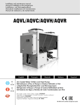
The table in fig.01 shows how to make up
the commercial code with twenty-four fields,
representative of the available options.
Available versions
N.B. the figures shown refer to the
dimensional specifications on pages 27-29.
STANDARD CONFIGURATION: consists of
the single block rooftop module with G4 flat
filters (efficiency according to EN779), direct
expansion coil (hot coil optional) (fig.1)
SMP : rooftop with 2-way mixing box rear
exhaust(1) (fig.2)
SM2: rooftop with 2-way mixing box side/
bottom exhaust(1) (fig.4)
SM3: rooftop with 3-way mixing box with
temperature free-cooling (fig. 7)
FT7: rooftop with panel pre-filters G3 and
rigid bag filters F7 (EN779) (fig.3)
REC: rooftop with plate type heat recovery
section and exhaust fan. The cross-flow
heat recuperator allows the sensible heat
recovery from the exhaust air with a winter
operation efficiency over 50%. The two air
flows (supply and exhaust) are completely
separated and therefore all types of
contamination are avoided. (fig.13)
G72, G92, G150: rooftop with condensation
heat generator with rated heating capacity
of 72 kW (2), 92 kW or 150 kW. The hot air
condensation generator is fed by methane
gas. The air is heated through the passage
over the surface of the combustion chamber
and heat exchanger pipes. The combustion
chamber is fully made of AISI 430 stainless
steel, while the surfaces in contact with
the condensate (exchanger, fume hood)
are made of AISI 304 L stainless steel to
give outstanding resistance to corrosion. It
is provided with an automatic reset safety
thermostat (fig.6).
NOTE:
(1) Damper without actuators and
recirculation damper upon request.
Units identification and description
RTE units are equipped with an adhesi-
ve label that summarizes the main tech-
nical data such as model, heat output
and cooling capacity, rated capacity of
the air in recovery and extraction and
electrical data.
For any future reference and for all
communication with the AERMEC SpA
must indicate the number.
In addition, each piece is accompanied
by targhettta with weight and other
information traceability.
The rating plate and the plate of the
weight of the package are applied out-
side the main rooftop, on the side panel
near the electrical panel inspected the
same.
The plate of the weight of each package
is applied externally on the panel addi-
tional inspections, or packaging.
RTE
RTE
R410A
Air heater model
Methane gas
consumption
G20 (15°C -
1013 mbar)
G72
2,3 - 8,3 mc/h
G92
3,2 - 10,4 mc/h
G150
4,7 - 16,4 mc/h

Manual selection, installation and maintenance 6
Roof-top units - RTE series-
Version combinations
Version combinations
SM2-FT7: rooftop with 2-way mixing box,
side/bottom exhaust and bag filters F7 (1)
(fig.5)
G72-SMP: rooftop with 72kW heat
generator and 2-way mixing box rear
exhaust (fig.8) (1)(2)
G72-FT7: rooftop with 72 kW heat
generator and bag filters F7 (fig.9) (2)
G92-SMP: rooftop with 92kW heat
generator and 2-way mixing box rear
exhaust (fig.8)
G92-FT7: rooftop with 92 kW heat
generator and bag filters F7 (fig.9)
G150-SMP: rooftop with 150kW heat
generator and 2-way mixing box rear
exhaust (fig.8)
G150-FT7: rooftop with 150 kW heat
generator and bag filters F7 (fig.9)
SM3-FT7: rooftop with 3-way mixing box
and bag filters F7 (fig.10)
SM2-G72:
rooftop with 72kW heat generator
and
2-way
mixing box (fig.11) (1)(2)
SM2-G92: rooftop with 92kW heat
generator and 2-way mixing box (fig.11) (1)
SM2-G150: rooftop with 150kW heat
generator and 2-way mixing box (fig.11) (1)
SM2-G72-FT7: rooftop with 72kW heat
generator, 2-way mixing box and bag filters
F7 (fig.12) (1)(2)
SM2-G92-FT7: rooftop with 92kW heat
generator, 2-way mixing box and bag filters
F7 (fig.12) (1)
SM2-G150-FT7: rooftop with 150kW heat
generator, 2-way mixing box and bag filters
F7 (fig.12) (1)
REC-FT7: rooftop with static heat recovery
unit and bag filters F7 (fig.14)
SM3-G72: rooftop with 72kW heat
generator and 3-way mixing box (fig.15) (2)
SM3-G92: rooftop with 92kW heat
generator and 3-way mixing box (fig.15)
SM3-G150: rooftop with 150kW heat
generator and 3-way mixing box (fig.15)
SM3-G72-FT7: rooftop with 72kW heat
generator, 3-way mixing box and bag filters
F7 (fig.16)
SM3-G92-FT7: rooftop with 92kW heat
generator, 3-way mixing box and bag filters
F7 (fig.16)
SM3-G150-FT7: rooftop with 150kW
heat generator, 3-way mixing box and bag
filters F7 (fig.16)
REC-G72: rooftop with static heat recovery
unit and 72kW heat generator (fig.17) (1)()
REC-G92: rooftop with static heat recovery
unit and 92kW heat generator (fig.17)
REC-G150: rooftop with static heat
recovery unit and 150kW heat generator
(fig.17)
REC-G72-FT7: rooftop with section with
heat recovery unit, 72kW heat generator
and bag filters F7 (fig.18) (2)
REC-G92-FT7: rooftop with crossflow
recovery unit, 92kW heat generator, and
bag filters F7 (fig.18)
REC-G150-FT7: rooftop with crossflow
recovery unit, 150kW heat generator, and
bag filters F7 (fig.18)
NOTE:
(1) dampers without actuators
(2) not available for sizes 260 - 300 - 350 - 400
e.g.: (REC+G72+FT7) is an example of version
combination. To see the sizes, refer to the sizes
chapter (page 25).

Manual selection, installation and maintenance 7
Roof-top units - RTE series-
Field 1, 2, 3,4
RTE
Field 5, 6, 7
240
260
300
350
400
Field 8 Versions
F cooling only
H heat pump
Field 9 Operation
0 Standard
L Low-noise operation (no 350 and 400)
A High temperature (no 350 and 400)
Field 10 Power supply
O ° 3~ 400 V -50 Hz (standard)
W TV2 3~ 230 V -50 Hz
Z TV3 3~ 460 V -60 Hz
Field 11 Versions and combinations (THE FIGURES INDICATED REFER TO THE SIZES FROM PAGE 25 TO 28)
0 ° Basic configuration (Fig. 1)
1 SMP 2-way mixing box rear exhaust (Fig.2) (1)
2 FT7 Bag filters F7 (Fig. 3)
A SM2 2-way mixing box side/bottom exhaust (Fig.4) (1)
B SM2-FT7 2-way mixing box, side/bottom exhaust and bag filters (Fig.5) (1)
C G72 Heat generator 72 kW (Fig. 6) (4)
D G92 Heat generator 92 kW (Fig. 6)
3 G150 Heat generator 150 kW (Fig. 6) (5)
E SM3 3-way mixing box with ventilator fan (Fig. 7 on dimensional indications)
F G72-SMP 72 kW heat generator and 2-way mixing box rear exhaust (fig.8) (4)
G G92-SMP 92 kW heat generator and 2-way mixing box rear exhaust (Fig.8)
4 G150-SMP 150 kW heat generator and 2-way mixing box rear exhaust (Fig.8) (5)
H G72-FT7 72 kW heat generator and bag filters F7 (Fig.9) (4)
I G92-FT7 92 kW heat generator and bag filters F7 (Fig.9)
5 G150-FT7 150 kW heat generator and bag filters F7 (Fig.9) (5)
J SM3-FT7 3-way mixing box with bag filters F7 (Fig.10)
K SM2-G72 72kW heat generator and two-ways mixing box(Fig.11) (1)(4)
L SM2-G92 2-way mixing box with 92kW heat generator (Fig.11) (1)
6 SM2-G150 2-way mixing box with 150kW heat generator (Fig.11) (1) (5)
M SM2-G72-FT7: 2-way mixing box with 72kW
heat generator and bag filters F7(Fig.12)
(1)(4)
N SM2-G92-FT7: 2-way mixing box with 92kW
heat generator and bag filters F7 (Fig.12)
(1)
7 SM2-G150-FT7: 2-way mixing box with 150kW
heat generator and bag filters F7 (Fig.12)
(1) (5)
P REC
Section with crossflow plate heat recuperator (Fig. 13)
Q REC-FT7
Section with crossflow plate heat recuperator and bag filters F7 (fig.14)
R SM3-G72 3-way mixing box with
72kW heat generator (Fig.15)
(4)
S SM3-G92 3-way
mixing box with 92kW heat generator (Fig.15)
8 SM3-G150 3-way
mixing box with 150W heat generator (Fig.15) (5)
T SM3-G72-FT7 3-way mixing box with
72kW heat generator and bag filters F7 (Fig.16)
(4)
U SM3-G92-FT7 3-way
mixing box with 92kW heat generator and bag filters F7 (Fig.16)
9 SM3-G150-FT7 3-way
mixing box with 150kW heat generator and bag filters F7 (Fig.16) (5)
V REC-G72
Section with crossflow plate heat recuperator and 72kW heat generator (Fig.17) (4)
Y REC-G92
Section with crossflow plate heat recuperator and 92kW heat generator (Fig.17)
Z REC-G150
Section with crossflow plate heat recuperator and 150kW heat generator (Fig.17) (5)
X REC-G72-FT7
Section with crossflow plate heat recuperator, 72kW heat generator, and bag filters F7(fig.18)(4)
W REC-G92-FT7
Section with crossflow plate heat recuperator
, 92kW heat generator, and bag filters F7(fig.18)
O REC-G150-FT7
Section with crossflow plate heat recuperator
, 150kW heat generator, and bag filters F7(fig.18) (5)
(1) = Dampers without actuators
(2) = The right or left direction refers to the direction of air flow inside the air handling sections
(3) = The coil to water connection side is always on the left
(4) = 72 kW Generator only available on RTE 240
(5) = No RTE 240 model
Unit configuration

Manual selection, installation and maintenance 8
Roof-top units - RTE series-
Field 12
Filter pressure switch /coil protection grille accessory
0 ° No accessory of the PF/GP type
2 BP Heat recovery unit with by-pass (option only valid if field 10 = P, Q, V, Y, Z, X, W, O)
3 PF Filter pressure switch
4 GP Condenser protection grille
5 PF+GP
6 BP+PF (option only valid if field 10 = P, Q, V, Y, Z, X, W, O)
7 BP+GP (option only valid if field 10 = P, Q, V, Y, Z, X, W, O)
8 BP+PF+GP (option only valid if field 10 = P, Q, V, Y, Z, X, W, O)
Field 13 Heating coil accessory
0 ° No battery
W BTR Two-row hot-water heating coil with three-way modulating valve (3)
E BRE 12 Two stages electric heating coil (12 kW)
F BRE 18 Two stages electric heating coil (18 kW)
G BRE 24 Two stages electric heating coil (24 kW)
H BRE 36 Two stages electric heating coil (36 kW)
Field 14 Outside coil treatment accessory
0 ° Coils with copper pipes and aluminium fins
A BSP Coil with copper pipes and pre-painted aluminium fins
B BSR Coil with copper pipes and copper fins
C BSS Coil with copper pipes and tin-plated copper fins
Field 15 Air intake accessory
0 ° Std. rear return air intake. If there is a return fan, the head is up to 150 Pa
(value always 0 when field 10 = 0, 1, 2, C, D, F, G, H, I, P, Q, V, Y, X, W)
M T1 Right side return air intake, rear fresh air intake
(option only valid if field 10 = A, B, K, L, M, N, 6, 7) (2)
N T2 Left side return air intake, rear fresh air intake
(option only valid if field 10 = A, B, K, L, M, N, 6, 7) (2)
P T3 Rear return and fresh air intake
(option only valid if field 10 = A, B, K, L, M, N, 6, 7) (2)
Q T4 Bottom return air intake, rear fresh air intake
(option only valid if field 10 = A, B, K, L, M, N, 6, 7) (2)
T T5 Right side return air intake, left side fresh air intake
(option only valid if field 10 = A, B, K, L, M, N, 6, 7) (2)
U T6 Left side return air intake, left side fresh air intake
(option only valid if field 10 = A, B, K, L, M, N,) (2)
R AI Bottom air intake, return fan available pressure up to 150 Pa
(option valid only if field 10 =E, J, R, S, T, U, 8, 9)
S AS Top air intake, return fan available pressure up to 150 Pa
(option valid only if field 10 =E, J, R, S, T, U, 8, 9)
W PA4 Rear air intake, return fan available pressure up to 300 Pa
(option valid only if field 10 = E, J, P, Q, R, S, T, U, V, Y, X, W, O)
Z Al+PA4 Bottom air intake, return fan available pressure up to 300 Pa
(option valid only if field 10 =E, J, R, S, T, U, 8, 9)
V As+PA4 Top air intake, return fan available pressure up to 300 Pa
(option valid only if field 10 =E, J, R, S, T, U, 8, 9)
Field 16 Air supply accessory
0 ° Bottom air supply, supply fan available pressure up to 200 Pa (standard)
D MA Top air supply, supply fan available pressure up to 200 Pa
E MS Left side air supply, supply fan available pressure up to 200 Pa (2)
F MD Right side air supply, supply fan available pressure up to 200 Pa (2)
G PM4 Bottom air supply, supply fan available pressure up to 400 Pa
H MA+PM4 Top air supply, supply fan available pressure up to 400 Pa
I MS+PM4 Left side air supply, supply fan available pressure up to 400 Pa (2)
L MD+PM4 Right side air supply, supply fan available pressure up to 400 Pa (2)
(1) = Dampers without actuators
(2) = The right or left direction refers to the direction of air flow inside the air handling sections
(3) = The coil to water connection side is always on the left
(4) = 72 kW heat generator only available on RTE 240
(5) = No RTE 240 model

Manual selection, installation and maintenance 9
Roof-top units - RTE series-
Field 17 Refrigeration circuit accessories
0 ° No refrigeration circuit accessory
1 DCPR Low temperature device (external temperature down to - 20 °C) (standard on the low noise operation
units)
2 TP Pressure transducers (standard in the heat pump version)
3 RUB Discharge and Liquid shut-off valves (for cooling only version)
4 DCPR+TP
5 DCPR+RUB
6 TP+RUB
7 DCPR+TP+RUB
Field 18 Enthalpy control accessories
0 ° No enthalpy control accessory
A PUC Humidification control provision
B FCH Enthalpic Freecooling
C DP Dehumidification and re-heating management
D PUC+FCH
E PUC+DP
F FCH+DP
G PUC+FCH+DP
Field 19 Electronic accessories
0 ° No electronic accessory
P PR2 Remote panel
S SSV RS485 interface card for supervision
Q SQA VOC air quality sensor (option only valid if field 10 = E, J, O, P, Q, R, S, T, U, V, Y, Z, W, 8, 9)
R PR2+SSV
T PR2+SQA (option only valid if field 10 = E, J, O, P, Q, R, S, T, U, V, Y, Z, W, 8, 9)
U SSV+SQA (option only valid if field 10 = E, J, O, P, Q, R, S, T, U, V, Y, Z, W, 8, 9)
V PR2+SSV+SQA (option only valid if field 10 = E, J, O, P, Q, R, S, T, U, V, Y, Z, W, 8, 9)
Field 20 Damper actuator accessory
0 ° Modulating damper actuator series for versions with SM3 and REC
(if field 10 = E, J, R, S, T, U, V, Y, X, W); no actuators in all the other case
1 SCSR Return air damper for SMP mixing box (if field 10 = 1, 4, F, G)
2 SCS2 Return air damper for SM2 mixing box (if field 10 = A, B, K, L, 6, M, N, 7)
3 SCM3 Modulating spring return actuator for versions with 3-way mixing box and heat recovery unit (that
contain the code SM3 or REC in the version)
4 SRP Return air damper for SMP mixing box and modulating damper actuator (if field 10 = 1, 4, F, G)
5 SR2 Return air damper for SM2 mixing box and modulating damper actuator (if field 10 = A, B, K, L, 6,
M, N, 7)
6 SCMP Return air damper for SMP mixing box and modulating spring return actuator (if field 10 = 1, 4, F,
G)
7 SCM2 Return air damper for SM2 mixing box, modulating damper actuator on fresh air and modulating
spring damper actuator on return air (if field 10 = A, B, K, L, 6, M, N, 7)
Field 21 Shock absorbing accessory
0 ° No shock absorbers
3 VT3 Rubber shock absorbers for units in basic version
5 VT5 Rubber shock absorbers for units from the 5m to the 7.1m
7 VT7 Rubber shock absorbers for units of over the 7.1m
Field 22 Inspection side
0 SX Left-hand supply inspection side (default) (if field 15 = 0, D, F, G, H, L)
1 DX Right-hand supply inspection side (if field 15 = 0, D, F, G, H, L)
Field 23 Condensate drain side
0 SX Left-hand condensate drain side (standard)
D DX Right-hand condensate drain side
Field 24 Special requirements
0 All according to catalogue
S Unit with at least one special requirement
(1) = Dampers without actuators
(2) = The right or left direction refers to the direction of air flow inside the air handling sections
(3) = The water coil connection side is always on the left
(4) = 72 kW Generator only available on RTE 240
(5) = No RTE 240 model

Manual selection, installation and maintenance 10
Roof-top units - RTE series-
Description of components
Refrigeration
circuit
Compressors
Scroll-type hermetic compressors with
crankcase heater provided as a standard in the
heat pump version (and in the only coolung
version, if provided with DCPR accessory)
Provided the unit is under voltage the heating
element is automatically switches on when the
unit stops.
Internal heat exchanger
Made with copper pipes and aluminium
fi ns locked into place through mechanical
expansion of the pipes. The coil is of the high
effi ciency type; grooved pipes and corrugated
fi ns.
External heat exchanger
Made with copper pipes and aluminium
fi ns locked into place through mechanical
expansion of the pipes. The coil is of the high
effi ciency type; grooved or smooth pipes
according to the size.
Liquid receiver
(only for heat pump version)
Thermostatic valve
The valve with external equaliser on the
evaporator outlet, modulates the gas fl ow to
the evaporator according to the heat load in
such a way as to assure a suffi cient degree of
overheating at the intake gas.
Drier-fi lter
Made of ceramics and hygroscopic material it
traps impurities and any traces of humidity in
the cooling circuit.
Sight glass
To check the refrigerating gas charge and verify
presence of humidity in the cooling circuit.
Solenoid valve
Switches on after the compressor has stopped,
interrupting the migration of the liquid
refrigeration gas to the evaporator.
Liquid and discharge shut-off valves (accessory
only available for the cooling only versions).
They stop the refrigerant fl ow in case of
extraordinary maintenance.
4-way valve (only for heat pump version)
To control the refrigerant fl ow for the summer/
winter mode changeover and to operate the
defrosting cycles.
Solenoid by-pass valve
(only for heat pump version)
The valve by-passes the thermostatic valve
during the defrosting cycles.
Safety valve
Set to 30 bar, it protects the circuit against
excessive pressures.
Check valve (only for heat pump version)
The valve allows the refrigerant to fl ow in one
direction only.
Frame and fans
Condensing section
It is provided with statically and dynamically
balanced axial fans. The fans are provided of
protection grilles while the electric motors
are protected by means of magnetothermal
switches.
Air handling section
It is provided with a double intake radial
fan with forward curved blades for better
performance and quietness. The fan is driven
by a three phases electric motor with belts and
adjustable pulleys.
Structure
The air handling section is made of 50
mm thick sandwich panels with type of
construction for the air treatment side is:
external peraluman sandwich-type panelling
and galvanised steel 50 mm thick inside with
injected polyurethane insulation (thickness 42
kg/m3). Accessible panels are provided with
proper knobs, while the others are set through
screws.
Control and safety
components
Door lock switch
For safety the electrical panel can only be
accessed by cutting off the power using the
opening lever on the panel itself. This lever
can be locked in place using one or more
padlocks, during maintenance in order to
prevent the machine being powered up
accidentally.
Control keyboard and display on the machine
This allows the complete control of the unit.
For a detailed description refer to the user
manual.
Electrical panel
Contains the power section and the
management of the controls and safety
devices. This conforms with standard CEI
60204-1, and electromagnetic compatibility
directives EMC 89/336/EEC and 92/31/EEC.
Antifreeze sensor (only with BTR)
When the water temperature is below +5°C,
the dedicated software, in the control card,
completely opens the three-way valve,
thereby circulating hot water through the
digital output signal.
Refrigerator circuit pressure switches
These are placed one on the high-pressure
side and one on the low pressure side of the
refrigeration circuit. They stop compressor
from operating in the case of abnormal
operating pressures.
Flow switch
This has the task of ensuring that air circulates
in the air handling section. If there is no air, it
switches off the unit.
High and low pressure transducers
(standard on the heat pump version)
Placed on the high- and low-pressure sides of
the refrigerator circuit making it possible to
show the value of the pressure on the display.
Optional on the cooling only versions.

Manual selection, installation and maintenance 11
Roof-top units - RTE series-
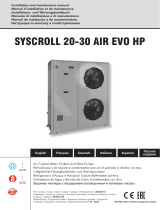
The architecture of the microprocessor
control (fig. 02) provides for:
• a BASE CARD with microprocessor
dedicated to the execution of the
control program, provided with
display, keyboard and LED to allow
for the programming of the set-points
and the basic user operations (on/off,
display of checked values, optional
print-out ).
• the program is written on the
EPROM while the set-points set are
memorised permanently on EPROM,
so that they can be kept even when
there is no power (without the need
for a support battery).
It is possible to connect the basic
card with the pLAN local network
(pCO Local Area Network) consisting
of different basic cards and terminals.
Each board can exchange data
(any parameter, whether digital or
analogue, depending on the program)
at high transmission speeds. Up to
sixteen units can be connected
(between cards and terminals) for a
maximum of 5 rooftops in such a way
as to share the information quickly.
The connection through the serial
supervision/remote assistance line in
accordance with the RS485 standard,
is made through optional serial cards
and MODBUS communication
protocol.
Thanks to its versatile software, the
user terminal permits:
• to modify the basic set points at any
moment which may be protected
with a password
• the display of the detected alarms
and their acoustic detection by means
of a beeper
• the indication of the active functions
by means of leds.
• the display of all the measured
parameters.
fig.02
G
0G
CNYS
1B
2B
3B
4B
DNG
FERV5
+
CDV42+
1Y
2
Y
3
Y
D
N
G
1
D
I
2DI
3DI
4
D
I
5D
I
6
D
I
1CDI
-XTXR
+XTXR
DNG
NALT
DNG
1
C
1ON
2ON
3ON
4C
4ON
5ON
5
C
5
C
N
1J 5J
6J
7J
8J
9
J
01J
11J
2
J
3
J
4J
CLOCK CARD
SERIAL CARD
built-in terminal
5.3 1
5.3 0
5.3 1
5.4 10
5.4 12
5.4 13
5.5 14
5.5 9
5.5 11
5.6 15
3.7 6
5.2 8
5.2 0
4.7 46
4.7 44
2.7 35
4.6 43
2.8 36
3.5 45
4.8 30
RT- 5.1
RT+5.1
GND5.2
82 2.3
84 2.3
89 4.4
86 2.5
82 2.6
87 2.6
88 3.4
82 3.4
Regulation system

Manual selection, installation and maintenance 12
Roof-top units - RTE series-
Accessories
DCPR - Pressure switch control device
Extends the operating range of the rooftop,
both in the summer cycle (minimum outside
air temperature to 10 ° C), and in the winter
with heat pump (maximum temperature
of outside air to 25 ° C). It also makes the
operation very quiet at part load. An
electronic control varies the speed of the fans
depending on the condensing condensing
pressure, which has a special transducer,
ensuring proper supply to the thermostatic
valve.
TP - Pressure transducers (standard on heat
pumps)
These show the high and low pressures on
a display, manage the compressor and valve
activities during defrosting and inhibit their
operation when the pressure exceeds the set
limits.
Discharge and liquid shut-off valves (only for
cooling only version).
Hermetic taps with manual closing on the
compressor supply on the circuit liquid side.
GP - Protection grills
They protect the external coils from
accidental blows and hail.
T1 - Air intake on the right side (only on the
SM2)
See page. 30.
T2 - Air intake on the left side (only on the
SM2)
See page. 30.
T3 - Rear air intake (only on the SM2)
See page. 30.
T4 - Bottom air intake (only on the SM2)
See page. 30.
AI - Bottom intake (only on the SM3)
See page. 31.
PA4 - Rear air intake
Return fan available pressure up to 300 Pa for
nominal flow rate.
MA - Upper air supply
Top air supply, supply fan available pressure
up to 200 Pa at the nominal air flowrate.
MS - Left air supply
Left air supply, supply fan available pressure
up to 200 Pa at the nominal air flowrate.
MD - Right air supply
Right air supply, supply fan available pressure
up to 200 Pa at the nominal air flowrate.
PM4 - Supply fan available pressure up to
400 Pa
Supply fan available pressure up to 400 Pa for
rated flow rate.
BTR- Two-row heating coil
Two-row hot water coil with three way
modulating valve. These can only be
managed in the post-heating phase with the
DP accessory.
BRE- Electrical heating coil
Two-stage heating electric heating battery
provided with double safety thermostat, one
automatic resetting and the other manual
resetting. The capacities proposed are 36,
48, 60 and 72 kW (or in the order phase
indicated the capacity required). These can
only be managed in the post-heating phase
with the DP accessory.
PUC- Provision for humidification control.
ON/OFF Contact (normally open) for
humidification enabling. The unit in this
case has humidity sensor situated on the
ambient air recovery. A humidity valve is
also supplied to be positioned down line
from the humidification section.
DP - Kit for the management of the
humidification and post heating
The control will force the operation of the
compressors to dehumidify the air up to
the humidity set point set. If there is a water
or electric coil, it will also be possible to
manage the post heating.
The PUC accessory can be combined
(humidification contact).
SCS - Damper actuators for two-way
versions
Modulating actuators fitted directly on the
exhaust air damper and external damper for
the management of the air change.
SCSM damper actuators with spring return
for 2-damper-valve versions
Actuators with spring return fitted directly
on the recovery air dampers and outside
air for the management of the air change,
in case of blackout completely close the
outside air damper and open the fresh air
damper completely.
SCM3 damper actuators with spring return
for 3-damper-valve versions
Actuators with spring return mounted
directly on the dampers for the management
of the freecooling to replace the standard
ones ; in case of blackout they close the
outside air dampers completely and open
the fresh air dampers completely.
FCH - Enthalpic Free-cooling
Only with three damper mixing box.
It manages the outside air flow and recovery
referring to their enthalpic values
.
PR2 - Remote panel
This enables rooftop control operations to be
carried out at a distance.
SSV - RS485 Serial interface for supervision
Serial card necessary for the supervision
system interface.
SQA - Air quality sensor
This analyses the quality of the air on the
basis of a mixed gas SnO2 VOC sensor by
assessing the contamination by polluting
gases. The presence of the sensor combined
with the rooftop control permits:
- the setting of a sensitivity threshold
depending on the maximum contamination
of the air predicted.
- the ventilation of the rooms only when
necessary so as to ensure energy saving.
TV2 - Power voltage 3~230V - 50HZ.
TV3 - Power voltage 3~ 460V - 60HZ.
VTR (3 - 5 - 7)- Shock absorbers
Rubber antivibration dampers. Select the VTR
model from the accessories table (see page 13).
PF - Filter dirtying pressure switch
BSP - Special batteries
Condensing coil with copper pipes and
prepainted aluminium fins.
BSR - Special coils
Condensing coil with copper pipes and
copper fins.
BSS - Special coils
Condensing coil with copper pipes and tin
plated copper fins.

Manual selection, installation and maintenance 13
Roof-top units - RTE series-
Available accessories table
Size 240 - 260 - 300 - 350 - 400
Version cooling only (F) hot pump (H)
Operation std L (no 350 and 400) A (no 350 and 400) std L (no 350 and 400) A (no 350 and 400)
DCPR o•oo•o
TP ooo•••
RUB ooo- - -
GP oooooo
T1 (1) oooooo
T2 (1) oooooo
T3 oooooo
T4 oooooo
AI oooooo
PA4 oooooo
MA oooooo
MS (1) oooooo
MD (1) oooooo
PM4 oooooo
BTR oooooo
BRE oooooo
PUC oooooo
DP oooooo
SCS oooooo
SCSM oooooo
SCM3 oooooo
FCH oooooo
PR2 oooooo
SSV oooooo
SQA oooooo
TV2 oooooo
TV3 oooooo
VTR3 (for basic version units) oooooo
VTR5 (for units from 5 to 7.1 m) oooooo
VTR7 (for units over 7.1 m) oooooo
PF oooooo
BSP oooooo
BSR oooooo
BSS oooooo
BSR oooooo
BSS oooooo
1) = The right or left direction refers to the direction of air flow inside the air handling sections
• = standard
o = optional
- = not available
Hot water coil data (BTR accessory)
RTE Size 240 260 300 350 400
Heating capacity (kW) 400 179 200 213 219
Rows (number) 22222
Hot water coil performance referred to : inlet air 20°C; water 80/70 °C;
N.B.: for data about the water flowrate, water side pressure drops and performances with conditions different from the standard
please see page. 24
Electrical coil data (BRE accessory)
RTE Size 240 260 300 350 400
Heating capacity (kW) 12 18 24 36 12 18 24 36 12 18 24 36 12 18 24 36 12 18 24 36
Number of stages 22222

Manual selection, installation and maintenance 14
Roof-top units - RTE series-
Performances referring to:
Room air 27 °C / 50% r.h.
External air 35 °C
* Energy indices referring to cooling circuit
Cooling only F (standard)
Version 240 260 300 350 400
Cooling capacity F kW 77.1 88.6 103.0 129.4 142.5
Sensible cooling capacity F kW 50.1 61.2 67.0 77.7 92.6
Total input power F kW 20.7 25.3 31.8 39.7 44.5
Condensing unit section
Compressors
Type F scroll
Number / circuit F n° 2/2 2/2 2/2 2/2 2/2
Capacity step control F % 0-50-100 0-50-100 0-50-100 0-50-100 0-50-100
Compressor input power F kW 16.04 18.87 23.56 30.13 33.95
L.R.A. (Locked Rotor Amps) F A 350 135 175 215 215
Axial Fans
Number / Input power F n°/kW 4x0.53 4x0.53 4x0.53 4x0.56 4x0.56
Air flow rate Fm
3/h 32000 29000 28000 40000 36000
Evaporator
Number of rows Fn°44444
RTE
Energy indices
E.E.R. * F 4.49 4.30 4.01 3.91 3.85
Air handling section
Fan
Type F Radial, forward curved blades
Nominal air flow rate Fm
3/h 40000 17000 20000 22000 23000
Minimum air flow rate Fm
3/h 10400 14800 17400 19100 19550
Maximum air flow rate Fm
3/h 14100 20000 23500 23500 23500
Number Fn°11111
Total installed power F kW 2.58 4.37 6.13 7.34 8.35
Available pressure with std motor F Pa 200 200 200 200 200
Air filters
Thickness Fmm5050505050
Efficiency F EN779 G4 G4 G4 G4 G4
Operating limits
Max. external air temperature F°C4343434343
Base version sizes
Height Fmm 1.830 1.830 1.830 1.830 1.830
Width Fmm 2.166 2.166 2.166 2.166 2.166
Lenght Fmm 3.290 3.290 3.290 3.290 3.290
Weight Fkg 1.300 1.390 1.480 1.565 1.645

Manual selection, installation and maintenance 15
Roof-top units - RTE series-
Heat pump H (standard)
Performances referring to:
Cooling mode: Ambient air 27 °C/50% r.h. External air 35 °C
Heat pump mode: Ambient air 20 °C/50% r.h. External air 7 °C/70% r.h.
* Energy indices referring to cooling circuit
Version 240 260 300 350 400
Cooling capacity H kW 76.3 87.7 104.9 128.2 141.1
Sensible cooling capacity H kW 49.6 60.6 66.3 76.9 91.7
Heating capacity H kW 73.4 86.3 103.0 127.6 142.2
Total input power in cooling mode H kW 20.4 25.0 30.8 38.5 43.1
Total input power in heating mode H kW 18.9 21.8 26.1 34.4 38.6
Condensing unit section
Compressors
Type H scroll
Number / circuit H n° 2/2 2/2 2/2 2/2 2/2
Capacity step control H % 0-50-100 0-50-100 0-50-100 0-50-100 0-50-100
Input power in cooling mode H kW 15.7 18.5 23.1 29.5 33.2
Input power in heating mode H kW 14.2 15.3 18.4 25.4 28.7
L.R.A. (Locked Rotor Amps) H A 350 135 175 215 215
Axial Fans
Number / Input power H n°/kW 4x0.53 4x0.53 4x0.53 4x0.56 4X0.56
Air flow rate Hm
3/h 36000 33000 32000 40000 34200
Evaporator
Number of rows Hn°44444
Energy indices
E.E.R.* H 3.7 3.5 3.4 3.3 3.2
C.O.P.* H 3.9 3.9 3.9 3.7 3.6
Air handling section
Fan
Type H Radial, forward curved blades
Nominal air flow rate Hm
3/h 14000 17000 20000 22000 23000
Minimum air flow rate Hm
3/h 10400 14800 17400 19100 19550
Maximum air flow rate Hm
3/h 14100 20000 23500 23500 23500
Number Hn°11111
Total installed power H kW 2.5 4.3 5.6 6.7 7.6
Available pressure with std motor H Pa 200 200 200 200 200
Air filters
Thickness Hmm5050505050
Efficiency H EN779 G4 G4 G4 G4 G4
Operating limits
Max. external air temperature H°C4343434343
Min. winter external air temperature
H °C -10 -10 -10 -10 -10
Base version sizes
Height Hmm 1.830 1.830 1.830 1.830 1.830
Width Hmm 2.166 2.166 2.166 2.166 2.166
Lenght Hmm 3.290 3.290 3.290 3.290 3.290
Weight Hkg 1.300 1.390 1.480 1.565 1725
RTE

Manual selection, installation and maintenance 16
Roof-top units - RTE series-
Performances referring to:
Room air 27 °C / 50% r.h.
External air 35 °C
* Energy indices referring to cooling circuit
Cooling only F-A (high temperature)
Version 240 260 300
Cooling capacity F A kW 78.0 89.9 105.6
Sensible cooling capacity F A kW 50.7 62.1 68.7
Total input power F A kW 20.3 24.8 30.7
Condensing unit section
Compressors
Type F A scroll
Number / circuit F A n° 2/2 2/2 2/2
Capacity step control F A % 0-50-100 0-50-100 0-50-100
Compressor input power F A kW 15.5 18.2 22.4
L.R.A. (Locked Rotor Amps) F A A 350 135 175
Fans
Number / Input power F A n°/kW 4x0.53 4x0.53 4x0.53
Air flow rate F A m3/h 14500 14000 16500
Evaporator
Number of rows F A n° 4 4 4
Energy indices
E.E.R.* F A 4.68 4.30 4.01
Air handling section
Fan
Type F A Radial, forward curved blades
Nominal air flow rate F A m3/h 14000 17000 20000
Minimum air flow rate F A m3/h 10400 14800 17400
Maximum air flow rate F A m3/h 14100 20000 23500
Number F A n° 1 1 1
Total installed power F A kW 2.58 4.37 6.13
Available pressure with std motor F A Pa 200 200 200
Air filters
Thickness F A mm 50 50 50
Efficiency F A EN779 G4 G4 G4
Operating limits
Max. external air temperature F A °C 46 46 46
Base version sizes
Height F A mm 1.830 1.830 1.830
Width F A mm 2.166 2.166 2.166
Lenght F A mm 3.290 3.290 3.290
Weight F A kg 1.300 1.390 1.480
RTE

Manual selection, installation and maintenance 17
Roof-top units - RTE series-
Heat pump H-A (high temperature)
Version 240 260 300
Cooling capacity H A kW
77.2 89.0 104.6
Sensible cooling capacity H A kW
50.0 61.1 68.0
Heating capacity H A kW
77.1 87.4 101.5
Total input power in cooling mode H A kW
20.0 24.4 30.4
Total input power in heating mode H A kW
19.2 22.1 26.9
Condensing unit section
Compressors
Type H A scroll
Number / circuit H A n° 2/2 2/2 2/2
Capacity step control H A % 0-50-100 0-50-100 0-50-100
Input power in cooling mode H A kW 15.3 17.9 22.0
Input power in heating mode H A kW 14.5 15.7 18.5
L.R.A. (Locked Rotor Amps) H A A 350 135 175
Axial Fans
Number / Input power H A n°/kW 4x0.53 4x0.53 4x0.56
Air flow rate H A m3/h 14500 14000 16500
Evaporator
Number of rows H A n° 4 4 4
Energy indices
E.E.R.* H A 4.59 4.51 4.31
C.O.P.* H A 4.81 5.06 4.98
Air handling section
Fan
Type H A Radial, forward curved blades
Nominal air flow rate H A m3/h 14000 17000 20000
Minimum air flow rate H A m3/h 10400 14800 17400
Maximum air flow rate H A m3/h 14100 20000 23500
Number H A n° 1 1 1
Total installed power H A kW 2.58 4.37 6.13
Available pressure with std motor H A Pa 200 200 200
Air filters
Thickness H A mm 50 50 50
Efficiency H A EN779 G4 G4 G4
Operating limits
Max. external air temperature H A °C 46 46 46
Min. winter external air temperature
.H A °C -10 -10 -10
Base version sizes
Height H A mm 1.830 1.830 1.830
Width H A mm 2.166 2.166 2.166
Lenght H A mm 3.290 3.290 3.290
Weight H A kg 1.300 1.390 1.480
Performances referring to:
Cooling mode: Ambient air 27 °C/50% r.h. External air 35 °C
Heat pump mode: Ambient air 20 °C/50% r.h. External air 7 °C/70% r.h.
* Energy indices referring to cooling circuit
RTE

Manual selection, installation and maintenance 18
Roof-top units - RTE series-
Performances referring to:
Ambient air 27 °C / 50% r.h.
External air 35 °C
* Energy indices referring to cooling circuit
Cooling only F-L (low-noise)
Version 240 260 300
Cooling capacity F L kW 68.7 84.5 102.6
Sensible cooling capacity F L kW 44.7 58.3 66.7
Total input power F L kW 24.8 27.3 32.1
Condensing unit section
Compressors
Type F L scroll
Number / circuit F L n° 2/2 2/2 2/2
Capacity step control F L % 0-50-100 0-50-100 0-50-100
Compressor input power F L kW 20.1 20.8 23.8
L.R.A. (Locked Rotor Amps) F L A 350 135 175
Fans
Number / Input power F L n°/kW 4x0.53 4x0.53 4x0.53
Air flow rate F L m3/h 9500 9000 11000
Evaporator
Number of rows F L n° 4 4 4
Energy indices
E.E.R.* F L 3.2 4.3 4.0
Air handling section
Fan
Type F L Radial, forward curved blades
Nominal air flow rate F L m3/h 14000 17000 20000
Minimum air flow rate F L m3/h 10400 14800 17400
Maximum air flow rate Hm
3/h 14100 20000 23500
Number F L n° 1 1 1
Total installed power F L kW 2.6 4.4 6.1
Available pressure with std motor F L Pa 200 200 200
Air filters
Thickness F L mm 50 50 50
Efficiency F L EN779 G4 G4 G4
Operating limits
Max. external air temperature F L °C 39 39 39
Base version sizes
Height F L mm 1.830 1.830 1.830
Width F L mm 2.166 2.166 2.166
Lenght F L mm 3.290 3.290 3.290
Weight F L kg 1.300 1.390 1.480
RTE

Manual selection, installation and maintenance 19
Roof-top units - RTE series-
Heat pump H-L (low-noise)
Version 240 260 300
Cooling capacity H L kW 68.0 83.6 101.6
Sensible cooling capacity H L kW 44.2 55.6 65.9
Heating capacity H L kW 74.5 83.6 98.5
Total input power in cooling mode H L kW 24.4 26.8 31.6
Total input power in heating mode H L kW 19.0 21.8 26.5
Condensing unit section
Compressors
Type H L scroll
Number / circuit H L n° 2/2 2/2 2/2
Capacity step control H L % 0-50-100 0-50-100 0-50-100
Input power in cooling mode H L kW 19.7 20.4 23.4
Input power in heating mode H L kW 14.3 15.3 18.3
L.R.A. (Locked Rotor Amps) H L A 350 135 175
Axial Fans
Number / Input power H L n°/kW 4x0.53 4x0.53 4x0.53
Air flow rate H L m3/h 9500 9000 11000
Evaporator
Number of rows H L n° 4 4 4
Energy indices
E.E.R.* H L 3.13 3.72 3.94
C.O.P.* H L 4.74 4.94 4.89
Air handling section
Fan
Type H L Radial, forward curved blades
Nominal air flow rate H L m3/h 14000 17000 20000
Minimum air flow rate H L m3/h 10400 14800 17400
Maximum air flow rate H L m3/h 14100 20000 23500
Number H L n° 1 1 1
Total installed power H L kW 2.6 4.4 6.1
Available pressure with std motor H L Pa 200 200 200
Air filters
Thickness H L mm 50 50 50
Efficiency H L EN779 G4 G4 G4
Operating limits
Max. external air temperature H L °C 39 39 39
Min. winter external air temperature
H L °C -10 -10 -10
Base version sizes
Height H L mm 1.830 1.830 1.830
Width H L mm 2.166 2.166 2.166
Lenght H L mm 3.290 3.290 3.290
Weight H L kg 1.300 1.390 1.480
Performances referring to:
Cooling mode: Ambient air 27 °C/50% r.h. External air 35 °C
Heat pump mode: Ambient air 20 °C/50% r.h. External air 7 °C/70% r.h.
* Energy indices referring to cooling circuit
RTE

Manual selection, installation and maintenance 20
Roof-top units - RTE series-
Operating limits
The units, in their standard configuration,
are not suitable for installation in a salty
environment.
N.B: If you wish to operate the
machine beyond the limits indicated in
the diagram, please contact AERMEC
engineering/commercial department.
If the unit is situated in particularly
windy environments it is necessary to
install a wind break protection to avoid
unstable operation of the DCPR device.
46
39
Alta temperatura (A)
Standard
Silenziata (L)
Winter mode:
(heat pump)
fig.03
Model 240 260 300 350 240 260 300 240 260 300
Version Standard Vers. High temp Vers.. (A) Quiet operation vers.(L)
Max. external temperature in cooling mode °C 43 46 46 46 39 39 39
Min. external temperature in cooling mode °C 20
Max. input temp. to evaporating coil in cooling mode °C 30
Min. input temp. to evaporating coil on cooling mode °C 18
Min. external temperature in heat pump mode °C -10
Max. external temperature in heat pump mode °C 20
Max. input temp. to evaporator coil in heat pump mode °C 24
Min. input temp. to evaporator coil in heat pump mode °C 10
(dry bulbe temperature)
Sound data
* 1 mt. away from the unit, ducted fan,
direction factor Q = 4.
Standard version and High Temperature version(A)
Total sound levels Octave band [Hz]
Lw tot
Lp tot *
125 250 500 1000 2000 4000 8000
[dBA]
[dBA]
Sound power levels Lw [dB]]
240 80 75 85 78 78 76 72 65 54
260 81 76 86 79 78 76 72 65 54
300 82 78 88 81 79 77 73 66 56
350std 85 79 92 85 82 79 75 68 58
Summer mode
Lw: sound power level
Lp: sound pressure level
Low Noise version (L)
Total sound levels Octave band [Hz]
Lw tot
Lp tot *
125 250 500 1000 2000 4000 8000
[dBA]
[dBA]
Sound power levels Lw [dB]
240 77 72 79 75 74 72 71 64 53
260 78 73 80 76 75 72 71 64 53
300 79 74 82 77 76 73 72 65 54
High temperature (A)
Quiet (L)
/