This manual has been provided to assist
you with lift installation and operation.
For further assistance please contact
your authorized Harmar dealer or
Harmar’s Technical Service department.
Tel: 866-378-6648
Fax: 816-537-0641
Enclosurewith
CommercialPlatformLift
HIGHLANDER
EPL400
EPL600
EPL800
EPL1000
EPL1200
EPL1400
P/N 630-00048 REV C

Table of Contents
Installing the lift
Using the Manual 2
When You Receive the Lift 3
Specifications 3
Safety 3
Code Requirements 4
Site Requirements 4
Required Tools 4
Required Materials 4
Preparing to Install the Lift 5
Controller Harness Connections 5
Placing the VPL 6
Installing the platform 8
Installing the outer guard panel 8
Installing the Enclosure walls 9
Installing the fixed ramp 11
Anchoring the Lift 12
Setting the Limit Switches 13
Verifying Operation of the Lift 14
Manual Override 15
Call-Sends (optional) 1
Top Landing Gate (optional) 1
EMI and Flush Strike (optional) 1
Alarm (optional) 1
Owner’s Section 1
Safety
Controls
Operating the Lift 2
Warranty 3
Using the Manual
This manual will provide step by step instructions on how to install and operate your lift. Read
and understand the entire manual before beginning to install the lift.
If you have any questions, contact Harmar technical service at 1-866-378-6648
2

When You Receive the Lift and Enclosure
• Check the lift and enclosure for shipping damage. If you see any damage, contact the freight carrier to
file a damage claim.
• Verify that the packing list attached to the exterior packaging reflects your intended order.
• Verify that you have received the items on the packing list.
Specifications
Payload Capacity 750 lbs
Vertical Travel 54” – 171”
Height 77” – 197”
Foot Print VARIES
Platform Sizes 36” x 60” or 42” x 60”
Input Voltage 115vac - 20a (or 24 VDC for DC lift, optional)
Control Voltage 24vac or 24vdc
Platform Speed 10 ft/min
Motor 1/2hp-90vdc or 1/2hp-24vdc
Safety
• Read all instructions in this manual before installing or operating the lift.
• Do not exceed the maximum payload capacity of 750 lbs.
• Do not ride on the lift until it is anchored in place.
•This product is designed only for lifting people and wheel chairs. Do not use it for any other purpose.
•Always wear eye protection while installing or servicing this product.
• Always disconnect this product from the electrical source before servicing it.
• Only use the fasteners supplied with this lift.
• Do not wear loose clothing or jewelry when working on this product.
• Do not disable any safety equipment or switches supplied with this lift.
• Stay away from all drive train components while the lift is operating.
3

Code Requirements
Your lift and enclosure have been designed to meet ASME A18.1 section 2 and 5 and CSA
B44/ASME A17.5, with the addition of certain options. Code requirements for Vertical Platform lifts vary
depending on location.
It is the installers’ responsibility to contact their local code enforcement office and determine all of the
regulations they are subject to. You must do this before installing the Vertical Platform Lift. If you have
questions about this, feel free to call Harmar to be directed to the right officials.
Site Requirements
115vac 20amp grounded circuit, if outdoor, GFI protected..
Minimum 5” thick , level, 3,500 psi reinforced concrete slab sized to your specific install drawing.
If you choose to install the lift in a pit so the platform is at floor-level, Harmar recommends that the pit
be sized to install the enclosure in it also.
Required tools
Step ladder
Extension ladder or scaffold (helpful for
tall units)
Hammer Drill
3/8" Masonry Drill Bit, min 8” long
Appliance Dolly
Hammer
Level
Measuring Tape
Socket Wrench Set
Socket wrench or drill extensions up to
two-feet long (if installing walls from
platform)
Phillips screwdriver or bits, size #2 & #3
Wire stripper and cutter
Conduit cutters, punches and tools
needed with electrical conduit
Required materials
Up to 14 concrete anchors, wedge-type. Harmar recommends securing the lift with our Anchor Kit p/n
If you use your own, we recommend 3/8-16 anchor bolts with embedment of 4 inches. These shall
have a min pull out strength of 3000 lbs-force. If used in an extreme environment (wet, salty), use
galvanized or stainless steel
Various shims, slotted preferred, but washers can work. Min reqd. about 1/16th thick, Qty, up to about
25 max. These are to align enclosure and lift with the building. Often these aren’t needed.
Lag screws or similar and washers to attach upper portion of the enclosure to the building. You may
need lumber for this step too.
Up to ten wire nuts, med size.
Caulking, outdoor 25 year-silicone preferred
Electrical conduit and fittings. For outdoor installation, use liquid-tite and appropriate fittings
4

Preparing to Install the Lift
Site Requirements:
Verify the surface the lift will mount to is smooth and level. This surface must be made from 3,500 psi
reinforced concrete with a minimum thickness of 4”.
Verify that there is enough space for the lifts foot print. Be sure to include space neccesary for platform.
Caution: Verify that you have overhead clearance and the lift complies with codes for
your area.
Determine if the overhead height of the enclosure will encounter any difficulties with the building
(soffits, building overhang, gutters) and determine a plan to deal with these.
For enclosures without a dome, code requires 6’ 8” of clearance above the platform floor when the
lift is at the upper landing. Overhead clearance is your responsibility
Since you’ve purchased a Harmar enclosure for your lift, side-to-side running clearances required
by codes are satisfied by this design.
Warning: If you’ve purchased a 3-sided enclosure, the area between the lower floor and
the top landing must be smooth and vertical so that the distance from the wall to the
platform will stay between 3/8” and ¾” to meet code. This is to eliminate any pinch
points. If you’re using your own upper flush-door, you must also assure the threshold
meets this dimension requirement too, so there won’t be a pinch point.
Electricity Requirements
The lift will require a 115 VAC 20 amp grounded electrical circuit.
Depending on local codes, this connection may need to be routed in electrical conduit and hard-wired.
If you have a dome and ventilation/light unit, you’ll need to get 115 VAC 4 amps to it also. This can be
wired in conduit to the upper terminal strip of the Pinnacle or separately,
Warning: Do not ride on the lift until it has been anchored in place.
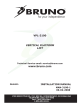
Controller Harness Connections
5
HighVoltage
CircuitBreaker
(ACunitonly)
LowVoltage
CircuitBreaker
Platform
TravelingCable
PhoneJack
Connection
SafetyPan
Jumper
UpperLanding
Interlock
LowerLanding
Interlock
Upper&Lower
Call‐Sends
Upper&Lower
LimitSwitches
BypassSwitches
(Strikesonly)

Placing the VPL:
Step 1
Unwrap and un-package the Vertical Platform
Lift as near to the installation location as
practical. Be careful to not scratch or damage
any of the panels. You’ll unwrap the platform
and its panels and a small-parts box. Just set
these out of the way for now.
Step 2
Since it’s shipped horizontal, you’ll need to stand
it up and move it to approximately where it will
be installed. These lifts weigh between 700 and
1100 lbs without their platforms, depending on
their height, but when lifting, you’ll only be lifting
one end,so half that weight. Though you may
use equipment such as a loader or a come-a-
long or winch to stand them up, three strong
people are usually sufficient to do this. If you use
equipment to stand it up, be sure to lift from the
heavy steel frame on the inside and use
straps—don’t lift from the outside body panels.
Note that a VPL for an enclosure differs from a
‘normal’ VPL because it does not have a top-cap
and its platform doesn’t have a safety pan. Part
of the enclosure will serve as the top cap, and a
pit-switch does the duty of the safety pan.
Step 3
Position the lift to the building according to the
dimensions below. Note that both platforms,36”
and 42” center on the door of the building, the
dimensions are shown below
Step 4
Install the tower-side walls that will be against
the building side onto the VPL lift. If it’s a very tall
lift, just put in a few lower ones, you can do the
rest when you have more of the enclosure
assembled. You’ll need to install the lowest one
first, that has vents. Note the one that has the
large hole in it for the pit switch will go on the
other side of the tower, don’t use it yet. To install
these to the tower, you’ll remove the screw that’s
in the tower and put the side panel there.
Step 5
Un-package the enclosure parts. If you’ve
ordered an enclosure with acrylic windows,
they’ll arrive with a paper or plastic protectors on
all but the outside edges of the windows. You
should leave these protectors on the windows
until you’re ready to finally place them; at that
time, you may peel and dispose of them. Also,
be careful not to scratch the powder coat on any
of these parts.
6

Step 6
Put the enclosure alignment panel across the
ends of the two tower legs. The panel is to
assure that you get the correct spacing of the
vertical panels to the lift.
Step 7
Next you’ll need to bolt together some of the
panels on the wall-side first because you won’t
have access to these bolts and holes when it’s
together. If you have a really tall tower, you’ll be
able to bend it out to put in the higher bolts, but
go ahead and build most of this. Use the 3/8” x
1.0 washer-face SS bolts that you use for most
of this assembly. Also, ‘pop’ a hole plug into the
outside hole of these after you’ve installed the
bolt. Next you’ll need to bolt together some of
the panels on the wall-side first because you
won’t have access to these bolts and holes
when it’s together. If you have a really tall
tower, you’ll be able to bend it out to put in the
higher bolts, but go ahead and build most of this.
Use the 3/8” x 1.0 washer-face SS bolts that you
use for most of this assembly. Also, ‘pop’ a hole
plug into the
Step 8
Put bolts through the tower side panels (step 5)
into the wall panels that you just installed (step
7). Same bolts as before.
Step 9
At this time, look at the spacing for the tower-
side panels and decide if you’re going to need to
shim the VPL unit to make it fit the wall. The
tower side panels’ edge needs to be parallel with
the wall. Depending on the angle, if it’s open at
the bottom, shim the wall, if open at the top, shim
the tower. The shims will have to go under the
enclosure walls that you haven’t put up yet also.
7

Installing the Platform
Step 1
The mounting bolts, nuts and spacers that
secure the platform to the lift carriage are
packaged in the small parts box. Begin by
locating these pieces and them setting aside.
Step 2
Position the platform by aligning the support
legs with the carriage flanges that protrude
from the front cover.
Step 3
Align the four mounting holes with those on
the carriage. Insert ½ x 3” hex head bolts
into each of the (4) holes. Install the low
profile nuts on the upper bolts and the
standard ones on the lower holes.
Step 4
Plug in the harness for the platform safety
pan and unplug the safety pan jumper on the
controller (ref pg 5). Secure the harnesses
under the clip on top of the carriage flange.
8

Installing Enclosure tower walls:
Step 1
Place and shim (if necessary) the lowest front
wall, the door frame and the tower-side walls on
the door-side of the enclosure. Again, the
lowest tower side-panel has the vent holes and
goes in ‘backward.’ This side has the big hole
for the pit-emergency stop switch. Assemble
and install the pit switch and its box. Note, the
doorframe may be received with the door
already installed.
Step 2
Install the rest of the front and tower-side
panels. Now you’re able to put on the Lift Top
Cap. For lifts taller than eight-foot lift, you may
skip ahead to the anchor-step, page 10.
Step 3
Your door will come assembled to the frame and
may already be on the unistrut (step 1) If not, put
eight twist-type strut-nuts into the channels. The
door assembly weighs more than 200 lbs, so lift it
with two people minimum and be careful not to
scratch it. Put eight bolts into it loosely. You’ll need
to adjust the position both vertically and horizontally
to match the threshold of the ramp (or upper
landing) If you have a gate, put the gate-mount
brackets on the other side (or door if it doesn’t have
a gate) and put install the pre-assembled gate.
9

Step 4
Whether the enclosure uses a fixed ramp or you
have a pit or have built your own ramp, the next
step is to adjust the height of the doors or gates
to fit their thresholds. Pry them gently to the
correct height with a piece of wood to prevent
damaging the finish. Check that the doors or
gates are properly centered on the platform,
then tighten the bolts. When you get the height
right, you may need to fine-adjust the lower and
upper stops on the lift to get it to stop in exactly
the right place,
Step 6
You can adjust the upper and lower limit switches to
make the lift stop exactly where needed.
Sometimes it comes from the factory right, so this
isn’t required.
Step 5
You have received one piece of Plexiglas that
isn’t installed in any frame, even if you have an
enclosure with metal panels. You will saw this
piece to fit exactly in the space that’s left above
the door after you’ve adjusted the height.
Measure the vertical height carefully, then mark
the desired width on the plex. Place it on saw
horses and clamp a long straight-edge to it,
adjusted for the specific circular saw you plan to
use. With a sharp blade, moving slowly, you
can saw the acrylic. Install the acrylic with
the angles and flats provided, which rivet in.
10

Installing the Platform Guard Panels
Step 1
Insert the guard panel posts into the pockets
in the platform. The smooth side of the
guard panels should face in toward the
center of the platform. Bolt each post in
place with (2) 5/16-18 x 2” and (1) ¼-20 x 2”
hex head bolts.
If you have a 90° exit platform, install the end
guard panel using the provided bracket and
bolt to inner guard panel.
Step 2
Install the platform control box on the rear
guard panel using screws and nuts through
the panel.
Step 3
Plug in the harness for the platform control
box. Secure the harnesses under the clip on
top of the carriage flange.
Installing Fixed
Ramp
Step 1
• Position the ramp after the lift is in its final
location.
• Maintain a gap of 3/8” to 3/4” between the
ramp and platform.
• Drill a pilot hole into the concrete and
fasten using supplied concrete lags through
ramp flanges.
11

Anchoring the Lift
Anchors
Harmar recommends securing the lift using
the concrete anchors provided. If you
purchase you own floor anchors they must be
3/8” minimum of sufficient length. All four
floor anchors must be installed correctly
in accordance to their instructions.
Step 1
• Position the lift in its final location.
• Verify that it is level and perpendicular to its
surroundings and all running clearances are
the proper dimension.
• Shim if necessary.
Step 2
Use the lift’s base as a template. Drill 4 holes
into the concrete making sure that the holes
are deep enough to accept the anchors.
Tip: Concrete dust may have settled into
the holes you just drilled. Use a shop
vacuum to clean out these holes. This will
ensure the floor anchors set correctly.
Step 3
Secure the lift in place by tightening the floor
anchor bolts.
Step 4 (800 or taller models)
Taller lifts must have the top of the lift
tower anchored into a solid surface to
ensure running clearances remain
constant.
There are two options for anchoring the top of
the tower:
1) For lifts going up to a landing such as a
deck or porch, the optional tower brace is
the preferred method. Instructions for the
brace are packaged with it.
2) For lifts that are placed with the back of
the tower against a solid wall such as
inside of a hoistway, drilling two holes
through the top tower cross brace and
anchoring is preferred.
12
Anchortwolocations

Setting the Limit Switches
Your lift is equipped with upper and lower limit switches. The vertical location of these switches may be
adjusted to fit your application. Typically the upper limit switch will need to be adjusted so the platform will
stop level with the upper landing. The lower limit will typically not need adjusting.
Step 1
Verify the emergency switch is in the ON
position. Run the lift in the up direction until
the platform floor is level with the upper
landing. Disconnect the lift’s power (at the
building’s circuit breaker for AC units, at the
battery box for DC units) before going to the
next step.
Warning: Moving components can cut
and crush. Do not operate the lift if you
are in close proximity to any drive
components. Be aware that loose
clothing or jewelry may catch on moving
parts.
Step 2
Remove the screws at the top of the lift that
attach the front cover.
Step 3
Remove the front cover by tilting it forward
and lifting upwards. The bottom of the front
cover sits on a pin on either side of the lift
frame. Set the cover aside in a safe location
where it will not get damaged.
Step 4
Loosen the bolts that attaches the upper limit
switch assembly. Slide the assembly down
the track until the lower switch in the
assembly comes in contact with the lift’s car.
You should hear the limit switch click as
contact is made. Retighten the set screw
fastening the limit switch assembly in place.
Step 5
Replace the front cover and secure it with
the screws you removed in step 1.
Step 6
Re-connect the lifts electricial power at the
circuit breaker. Verify that the emergency
switch is in the on position.
Step 7
Run the lift in the down direction for several
inches. Next, run the lift in the up direction.
Continue to press the up button until the
upper limit switch has caused the lift to stop.
Verify that the platform has stopped level
with the upper landing. If it has not, readjust
the limit until it is level.
13

Verifying Operation of the Lift
Caution: Complete the following section before training the customer to use
the lift.
Step 1
Run the lift up and down for 5 complete cycles. Hold the direction button down and allow the limit
switches to stop the lift. At the top, verify that the platform stops level with the upper landing. At the
bottom, verify the access ramp (if equipped) unfolds and rests on the ground.
Step 2
Verify the operation of the Emergency stop switch. When this switch is pushed in the lift should not run in
either direction. When this switch is turned and pulled back out, the lift should operate normally.
Step 3
Verify the operation of the sensor pan underneath the platform. Start with the lift at the top landing. Press
up on the sensor pan. While holding the pan in this location, press the down switch on the platform. The
lift should not run.
Warning: Do not run the lift if anyone is under the platform.
14

Manual Override
Your lift is equipped with a manual
handcrank, to be used in the case of a power
failure.
Step 1
Before using the manual handcrank verify
that it’s use is required. Check that the
emergency stop switch is pulled out. Check
that the electrical cord is connected to the
supply. Also check that the buildings circuit
breaker has not tripped. Try to run the lift by
pushing both the up and down buttons. If the
lift still will not run, complete the following
steps:
Step 2
Disconnect the power from the lift.
Warning: Do not service or operate the
manual handcrank while the lift is
connected to electricity.
Step 3
Remove the screws and remove the top cap
at the top of the tower.
Step 4
Insert the manual handcrank into the
opening on the top of the brake assembly. It
may be necessary to slightly rotate the
handcrank until it fully seats down on the hex
portion of the brake. Rotate the crank to
raise or lower the platform.
Warning: Never operate the lift while the
manual override crank is inserted into the
lift.
Call-Sends (optional)
The optional Call-Send controls are to be
used at the upper and/or lower landings to
call the platform to you or send it to the other
landing.
They should be mounted on the wall at each
landing at a convenient height. Consult local
codes for placement with consideration to
clearances.
15
Alengthofmulti‐conductorwirewill
needtoberunfromthebottomofthe
lifttoweruptothelandingCall‐Sends.
Consultlocalcodesfortypeand
mountingrequirements.Afterwiringis
completed,thewiringharnessmustbe
pluggedintoitappropriatereceptacleon
thecontroller(refpg5).
WiringConnections
Call‐Send LiftHarness
Blue Blue
White White
Red Red

Top Landing Gate (optional)
The optional top landing gate is provided with a combination
mechanical lock and electric contact (interlock).
The interlock:
Prevents the lift from running if the gate is not closed.
Prevents the gate from being opened if the platform is
not at the top landing.
Unlocks when the lift is on the upper limit switch.
A crescent shaped key is provided to manually unlock the gate
during installation. The key is inserted from the back
side to lift up on the solenoid that holds the gated
locked.
Mount the gate by placing onto the upper landing
making sure to align the gate opening with the platform
(outer guard rail not shown for clarity).
There are a number of attachment holes provided in the
threshold portion of the gate for mounting using wood
lag screws or concrete anchors as appropriate.
Remove the latch post cover and connect the call-send
and interlock wire harnesses.
The vertical posts of the gate must be attached to a
supporting structure, (the gate is not designed to be
freestanding).
16
Alengthofmulti‐conductorwirewill
needtoberanfromthebottomofthelift
toweruptothelandinggate.Consult
localcodesfortypeandmounting
requirements.Afterwiringiscompleted,
thewiringharnessmustbepluggedinto
itappropriatereceptacleonthe
controller(refpg5).
WiringConnections
InterlockHarnessLiftHarness
Black Black
Black Green
Yellow White
Yellow Orange
*Blue
*Brown
*Mustbetiedtogether
Call‐SendHarness LiftHarness
Blue Blue
Yellow White
Red Red

EMI and Flush Strike Interlocks (optional)
The optional EMI or Flush Strike Interlocks are provided
with a combination mechanical lock and electric
contact. They are to be used with existing doors.
The interlock:
Prevents the lift from running if the door is not
closed.
Prevents the door from being opened if the
platform is not at the landing.
A length of multi-conductor wire will need to be ran from
the bottom of the lift tower to each interlock. Consult
local codes for type and mounting requirements. After
wiring is completed, the wiring harness must be
plugged into it appropriate receptacle on the controller
(ref pg 5).
Flush Strike Interlock
Refer to the instructions inside the strike box for
mounting requirements.
EMI Interlock
1) Position interlock to door jamb and mark
mounting holes.
2) Fasten Interlock to door jamb with #8 wood
screws.
3) Route 4-conductor Interlock cable thru hole in
top of interlock and make wire connections.
4) Attach door keeper and emergency key plates
to hoistway door.
17
EMIInterlockWiringConnections
EMILiftHarness
Black(A) Black
Black(B) Green
Yellow(C) White
Yellow(D) Orange
N/A Blue+
N/A Brown+
N/A Red
+MustbetiedtogetherwhenusinganEMIInterlock.
FlushStrikeInterlockWiringConnections
ForACpoweredlifts
FlushStrikeWiresRectifierWiresLiftHarnessWires
Black‐WhiteStripeRed
Black‐WhiteStripeBlack
YellowBlack
YellowGreen*
YellowWhite
BlueOrange
GreyBlue
GreenBrown
RedRed
BlackBlack
YellowRed
YellowGreen*
ForOptionalDCpoweredlifts
FlushStrikeWiresLiftHarnessWires
Black‐WhiteStripeBlack
Black‐WhiteStripeGreen*
YellowWhite
BlueOrange
GreyBlue
GreenBrown
RedRed
BlackGreen*
*Thisisasin
g
lewirethatwillhave2wiresconnectedtoit.

Platform Control with Optional E-Stop Alarm
1
If equipped, the e-stop button on the platform lights up and sounds an alarm
when pressed.
You will need to obtain a 6 volt lantern battery like the example below.
The battery can sit under the top cap to the right of the motor pulley. There is a wire
harness for the battery located here. Wire #1 connects to the positive terminal and wire
#2 to the negative terminal.

Commercial Platform Lift - Owners Section
Read the manual thoroughly before operating the lift.
19

Congratulations on the purchase of your Harmar Vertical Platform Lift. This lift has
been engineered to provide trouble free service for many, many years. Please
read this manual completely before operating your lift.
Safety
• Do not exceed the maximum payload capacity of 750 lbs.
• Do not ride on the lift until it is anchored in place.
• This product is designed only for lifting people and wheel chairs. Do not use it for any other purpose.
• Make sure any obstructions are cleared from underneath the platform area before use.
• Make sure both the passenger and wheelchair are completely on to the platform before using.
• Do not disable any safety equipment or switches supplied with this lift.
• Do not attempt to service the lift yourself. Contact your Harmar dealer for assistance.
• Do not allow children to operate or play around the lift.
• Read all instructions in this manual before installing or operation the lift.
20
Page is loading ...
Page is loading ...
Page is loading ...
Page is loading ...
Page is loading ...
Page is loading ...
Page is loading ...
Page is loading ...
Page is loading ...
Page is loading ...
Page is loading ...
Page is loading ...
/