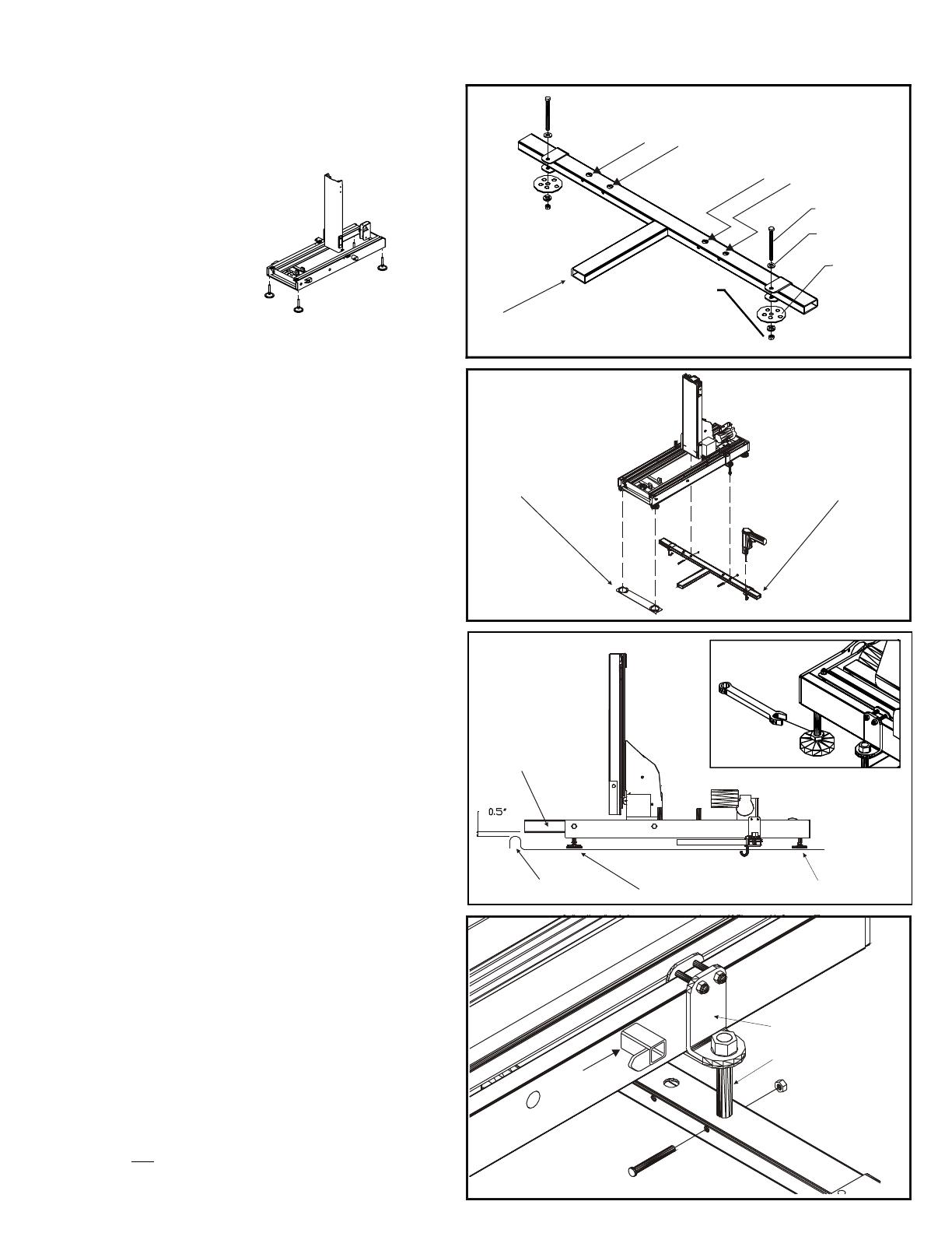
This part of the leg assembly must
face toward the rear of the vehicle.
Leg Assembly
5/16 x 4” Bolt
5/16” Washer
Installation
Washer
5/16” Lock
Washer
5/16” Nut
Installing in Vehicles Without a Removable Third Row Seat
Installing the Leg Assembly: Place the leg assembly into
the vehicle. Orientate the leg assembly as shown in the
drawing to the right. Also place the foot plate in the vehicle
near the rear opening. This will support the two rearmost
feet of the lift and keep the feet from pressing into the floor
pan of the vehicle.
Pick up the lift and place it into the vehicle’s cargo area. This
operation will require two people to perform. Take care
during this operation not to scratch the vehicle’s interior.
Position the lift such that it will be one inch inside of the rear
door. Verify this by closing the rear door and inspecting the
fit from inside of the vehicle.
Position the leg assembly so that it is located in line with the
hold down rods on either side of the lift. (See the picture at
the bottom of this page.) If needed you may slide the hold
down brackets along the lift’s body.
Remove the J-bolts from the leg assembly and replace them
with the hardware shown in the drawing to the right. Use an
11/32” drill bit to drill holes though the vehicle floor for
attaching the 5/16” bolts.
Caution! Inspect the underside of the vehicle for obstacles
before drilling any holes. Avoid the vehicle’s wiring, fuel
lines, fuel tanks, spare tires, seat cushions, etc.
From beneath the vehicle attach the installation washers,
5/16” lock washers and 5/16” nuts. Verify that the leg
assembly is centered from side to side within the vehicle.
Tighten the nuts on the 5/16” bolts until the assembly is
firmly attached to the vehicle.
If the vehicle has a lip at the rear door you will need to use
the adjustable feet to raise the entire lift so that all of its
moving parts will clear the door lip.
Use a wrench to extend the adjustable feet until the lift’s
middle stage will clear the door lip and door latch by 0.5”.
Leveling the lift: The floor in some vehicles is not level.
To level the lift start by parking the vehicle on level
ground. Use a carpenter’s level to verify the lift is level.
If it is not, adjust the four feet until the lift is level.
Attaching the lift into the vehicle: The leg assembly has
two sets of large holes in its upper surface. When
installing a Pioneer for use with a scooter, select the holes
that will offset the lift to the driver’s side of the vehicle.
When installing the Pioneer for use with a power chair,
select the holes that will offset the lift to the passenger's
side of the vehicle. Insert both hold down rods into the
holes in the Leg Assembly. Crossbolt the hold down rods
in place with the supplied hardware. Tighten the 5/8” nuts
on the hold down rods, until the lift is attached securely to
the vehicle.
Hold Down Rod
Hold Down Brackets
Foot Plate
Leg Assembly
Middle Stage
Rear Door Lip
Adjustable Feet
Foot Plate
POWER CHAIR
POWER CHAIR
SCOOTER
SCOOTER
PLATFORM
KEEPER
Caution: Do not remove the hold down brackets and
reattach them on the opposite side of the Platform Keeper.
Install the 4 Leveling Pads from
the hardware pack at this time.
Each Pad will thread into the
underside of the base at
each corner. Leveling
adjustment can be after
the lift has been installed.