Page is loading ...

Teflon Tape
1
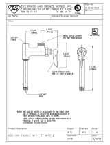
ROUGHING-IN DIMENSIONS
43-1/16"
(1094mm)
27-3/4"
(705mm)
38-3/16"
(970mm)
FINISHED WALL
16-3/4"
(426mm)
25-1/2"
(650mm)
1-1/4"
(32mm)
8-1/8"
(206mm)
2" DIA.
(50mm)
1/2" SUPPLIES
(13mm)
1/2"-14 NPT(13mm)
SUPPLY INLETS
“T”-CONNECTOR
HOT
COLD
FINISHED
FLOOR
4-3/4" DIA.
(120mm)
2764.951
Certified to comply with ANSI A112.18.1
Installation
Instructions
M 9 6 5 14 0 R E V. 1. 1
Thank you for selecting American-Standard...
the benchmark of fine quality for over 100 years.
To ensure that your installation proceeds smoothly--
please read these instructions carefully before you begin.
Recommended Tools
Flat Blade Screwdriver
Adjustable Wrench
Channel Locks
Tubing Cutter
CLEAN FREESTANDING
SINGLE CONTROL BATH FILLER
Phillips Screwdriver
Pipe Wrench
1-1/4" Hole Saw
Electric Drill

1
2
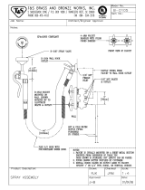
INSTALL SUPPLY HOSES AND RISER TUBES
TO VALVE BODY
INSTALL BATH SPOUT AND HANDLE
TO TUB FILLER
Turn off hot and cold water
supplies before beginning.
CAUTION
3
1
5
5
2
4
FLANGE
FAUCET BODY
M 9 6 5 14 0 R E V. 1. 1
Install SPOUT (1) into faucet body. Make sure
O-RING (2) is installed and not damaged.
Hand tighten SPOUT NUT (3). Align and center the
SPOUT (1) with the center line of the faucet body.
With an adjustable wrench fully tighten the SPOUT
NUT (3).
Note: Be careful not to scratch faucet while
tightening SPOUT (1).
Insert HANDLE (4) on CARTRIDGE STEM, tighten
SET SCREW (5) with HEX WRENCH (6) supplied.
Install INDEX BUTTON (7) into HANDLE (4).
1
2
3
MANIFOLD
2
Thread Hot and Cold SUPPLY HOSES (5) into MANIFOLD
using a wrench or adjustable wrench. Make sure the
connections are tight. Use Red tape (not supplied) to
indicate the Hot SUPPLY HOSE. SEE VIEW “A”
Insert RISER TUBE (1) without the flange over SUPPLY
HOSES (5). Thread the RISER TUBE (1) into base of the
VALVE BODY (2) and tighten fully.
Slide the FLOOR MOUNTING FLANGE (3) onto the RISER
TUBE (4) with the flange. Thread RISER TUBE (4) into
the bottom of RISER TUBE (1) and fully tighten.
Note: Be careful not to scratch the faucet while
tightening the tube assembly.
H
C
VIEW A
VIEW A
“C” COLD SUPPLY
“
H” HOT SUPPLY
“
H” HOT SUPPLY
HOT
CARTRIDGE STEM
4
5
6
7

FIGURE 1.
Determine the distance from the finished wall to the center of the floor
water supply holes and mark a centerline.
Note: Check that floor is level in both directions.
Drill a 2" (51mm) diameter hole for the 1/2" Hot and Cold supplies.
Slide MOUNTING FLANGE (1) downwards on the TUB FILLER ASSEMBLY (2).
Place MOUNTING FLANGE (1) over the floor supply hole.
Align and center the TUB FILLER ASSEMBLY (2).
FIGURE 2.
With the TUB FILLER ASSEMBLY (2) aligned and in desired
position, mark on the floor the three mounting holes for the
MOUNTING FLANGE (1).
DETERMINE MOUNTING LOCATION
3
FIGURE 3.
Drill three 1/4" (6mm) diameter holes 1-3/4" (44mm) deep.
Install the three ANCHORS (4) supplied, flush with the top of the
finished floor.
1
2
2
1
4
Level
BASE BOARD
(1) 2" (51mm)
DIA. HOLE
FINISHED WALL LINE
FIGURE 1
FIGURE 2
FIGURE 3
M 9 6 5 14 0 R E V. 1. 1
3
HOT

FIGURE 1:
Make sure FLEXIBLE HOT and COLD WATER SUPPLIES
protrude through the 2" (51mm) diameter hole in the floor
enough to make the supply connections to the
“T” ADAPTER (4).
FIGURE 2:
Hold the TUB FILLER ASSEMBLY (1) in place and install
the three MOUNTING SCREWS (2).
Check aligment and level before fully tightening the MOUNTING
SCREWS (2). After tightening the MOUNTING SCREWS (2) push
in the three PLUG BUTTONS (3).
INSTALL TUB FILLER ASSEMBLY
INSTALL WATER SUPPLIES AND “T” ADAPTER
4
FIGURE 1
FIGURE 2
1/2" SUPPLIES
(13mm)
HOT
COLD
1-1/4" (32mm)
M 9 6 5 14 0 R E V. 1. 1
1
2
6
3
FIGURE 3
FIGURE 3:
Apply sealing tape to the threads of the“T” ADAPTER (4)
and the two SUPPLY ADAPTERS (5). Thread the two
SUPPLY ADAPTERS (5) onto the “T” ADAPTER (4) and
tighten fully.
From below the floor, connect the HOT WATER SUPPLY
HOSE (6) (marked with red) to the Hot water supply
from the “T” (4) and the COLD WATER SUPPLY HOSE (7)
to Cold water supply from the “T” (4). Use an adjustable
wrench or 7/8" open end wrench to tighten connections.
Do not over tighten.
Secure piping below floor to floor joist.
4
5
5
1/2"-14 NPT
(13mm)
1/2"-14 NPT
(13mm)
PIPE SUPPORT
RED (HOT)
COLD
SUPPLY
HOT
SUPPLY
7
SEALING TAPE
FINISHED FLOOR
SUB-FLOOR
4
HOT
HOT
HOT

Install SEALS (1) on both ends of the SPRAY HOSE (2) and
connect the one end with the hex nut to the TUB FILLER
ASSEMBLY (3) using an adjustable wrench. Hand tighten
the connection to the HAND SHOWER (4).
Note: When not in use, the HAND SHOWER (4) should
be seated in the HOLDER (5).
INSTALL HAND SHOWER
5
Move HANDLE (6) into “off” position and remove AERATOR (7).
Turn on water supplies and check all connections for leaks.
Operate HANDLE (6) on to off, hot and cold to flush water
lines thoroughly.
Lift HAND SHOWER (4) from the holder and direct spray into tub.
Pull DIVERTER KNOB (8) and check HAND SHOWER (4) and
HOSE (2) connections for leaks.
Push DIVERTER KNOB (8) in and place HAND SHOWER (4) into
HOLDER (5).
TEST INSTALLED FAUCET
6
HEX NUT
1
1
2
3
4
5
6
8
7
M 9 6 5 14 0 R E V. 1. 1
7
DO: SIMPLY RINSE THE PRODUCT CLEAN WITH CLEAR WATER. DRY WITH A SOFT COTTON FLANNEL CLOTH.
DO NOT: DO NOT CLEAN THE PRODUCT WITH SOAPS, ACID, POLISH, ABRASIVES, HARSH CLEANERS, OR A
CLOTH WITH A COARSE SURFACE.
CARE INSTRUCTIONS:
5

M964073-0070A
CARTRIDGE
M964067-0020A
HANDLE KIT
M964068-0070A
T-CONNECTOR
ASSEMBLY
M964060-0020A
AERATOR ASSEMBLY
M964071-0020A
HAND SPRAY
M964070-0020A
HAND SPRAY HOSE KIT
M964069-0070A
SCREW & ANCHOR KIT
M 9 6 5 14 0 R E V. 1. 1
For toll-free information and answers to your questions, call:
1-800-442-1902
Weekdays 8:00 a.m. to 6:00 p.m. EST
IN CANADA 1-800-387-0369 (TORONTO 1-905-306-1093)
Weekdays 8:00 a.m. to 7:00 p.m. EST
IN MEXICO 01-800-839-1200
Product names listed herein are trademarks of American Standard Inc.
© AS America, Inc. 2011
HOT LINE FOR HELP
MODEL NUMBERS
2764.591
CLEAN FREESTANDING
SINGLE CONTROL BATH FILLER
M964072-0020A
DIVERTER ASSEMBLY
6
M964114-0070A
SUPPLYHOSES
/