Page is loading ...

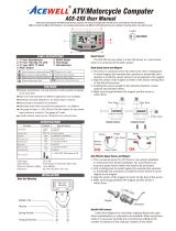
and 80.0Km/H or 50.0 MPH for ACE-21XXE.
AVG: Average Speed Meter
The AVG is calculated by dividing the TRIP by the RT (riding time).
MAX: Maximum Speed Meter
Displays the highest speed achieved from the last Reset operation.
TRIP 1&2: Trip Meter 1&2
TRIP function accumulates trip distance since last RESET as long as
bike/vehicle is moving.
ODO: Odometer
The ODO accumulates total distance as long as the electric bike/scooter is
being ridden. The ODO data is always stored to memory even when the
power is turned off.
RT: Riding Time
The RT totals the riding time from the last RESET operation.
TT: Total Time
The TT accumulates total time as long as the electric bike/scooter is being
ridden. The TT data always be stored to memory even the power is removed.
: 12/24 hour Clock
It displays 12 or 24 hour current time.
Battery Gauge:
1.The battery gauge has 7 bars to indicate how much power the gauge
remains.
2.The 1st bar indicates the low voltage of the battery, the more bars shows
more voltage, all 7 bars indicates maximum voltage of the voltage.
3.The last bar will flash to alert you to charging battery soon. MA
: Bar Graphic Speed meter
It displays bar graphic speed up to 125 Km/H or 78 MPH for ACE-22XXE and
80Km/H or 50 MPH for ACE-21XXE.
SPD: Speed Meter
It displays digital speed meter up to 125.0 Km/H or 78.1 MPH for ACE-22XXE
FEATURES
FUNCTIONS
WHEEL CIRCUMFERENCE TABLE
BUTTON OPERATION
PANEL DESCRIPTIONS
E
13
10R-022811
Computer
ACE-2XXXE User Manual
Electric Bike/Scooter
Thanks for purchasing the electric bike/scooter computer; this manual
is specifically designed for ACE-2XXX-E series, which has different
models, each model has different LED indicators. You may find that
the photo has a set of LED indicators different from your computer,
the photo is for reference only
Multi-functional LCD Electrical Bike/Vehicle computer displays
analogue and digital Speedometers, power gauge and one of other
functions at the same time.
Computer built-in 4 to 6 LED lights for different purpose indicators.
Odometer and total riding timer are stored in memory, even when the
power is off.
Back light design and Odometer always be stored to memory follows
CE regulation.
Displays clock even when other functions is off.
Wide wheel circumference setting rang: 1-3999mm.
Metric/Empire unit option available.
Water resistant tested 100%.
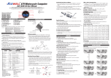
SPECIFICATIONS
Bar Speed Meter
Speed Meter
Maximum Speed Meter
Average Speed Meter
Trip Meter 1&2
Riding Time
Total Time
Clock
Battery Gauge
Odometer
FUNCTIONS Symbol ACE-21XXE ACE-22XXE
2.5-80Km/H (50MPH)
2.3-80.0Km/H (50MPH)
2.3-80.0Km/H (50MPH)
2.3-80.0Km/H (50MPH)
0.00-9999.99 Km
(6249.99Miles)
0.0 – 99999.9 Km
0.0- 62499.9 Miles
0.00’00”- 99:59’59”
9999H59’
5-125Km/H (78MPH)
2.3-125.0Km/H (78.1MPH)
2.3-125.0Km/H (78.1MPH)
2.3-125.0Km/H (78.1MPH)
0.00-9999.99 Km
(6249.99 Miles)
0.0 – 99999.9 Km
0.0- 62499.9 Miles
0.00’00”- 99:59’59”
9999H59’
0:00’00”-11H59’59”/23H59’59”
1-7Bars, customize voltage
MAX
AVG
TRIP 1/2
ODO
RT
TT
SPD
Wheel Circumference setting: 1mm - 3999 mm (1 mm increment)
Operation Temperature: -20°C - +70°C
Speed Sensor: No Contact Magnetic Sensor.
Storage Temperature: -25°C - +80°C
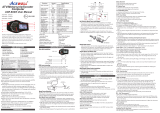
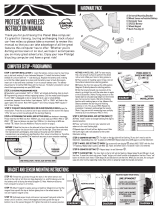
MODE BUTTON
1.Press the MODE button to move in loop sequence from one function
screen to another
2.The LCD screen will convert to the screen of Speed meter and trip
meter automatically during the riding, if the button operation is
suspended for 10 seconds.
RESET BUTTON
1.Hold down the RESET button for 2 seconds at the function’s screen
desire to be reset. The computer will reset the TRIP, RT or MAX data
from stored values to zero
2.It cannot reset ODO and TT data
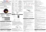
1.The details below have been calculated using following formula: Tire
Diameter (inches) x 25.4(mm/inches) x 3.1416 = wheel circumference (in
mm).
2.Identify the tire size of your electric bike/scooter when you need to change
different tire size and key in the corresponding number shown in the
following chart.
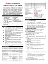
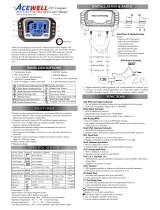
1
2
3
4
8
5 6
7
Reset
2sec
1. Bar Speed Scale
2. Bar Speed
3. Speed & Max. speed display
4. Other functions display
5. RESET Button
6. MODE Button
7. Voltage Meter
8. LED indicator symbols
Tire Size
Circumference
number
(mm)
Tire Size
Circumference
number
(mm)
Tire Size
Circumference
number
(mm)
23 inch
24 inch
25 inch
26 inch
19 inch
20 inch
21 inch
22 inch
15 inch
16 inch
17 inch
18 inch
1835
1915
1995
2075
1516
1596
1676
1756
1197
1277
1357
1436

Clock,Wheel and Units SETUP
PRECAUTION
Installation
1.Setup operations include 12/24HR clock, wheel circumference and units. You have to set up step by step. The computer will automatic reversion to main
screen if no button operation for 20 seconds at any setting screen.
2.Press both MODE & RESET buttons to go into setting mode.
3.In setting mode, each press of the RESET button increments the flashing digit by 1 or converts units. Press MODE button to confirm the digit setting and
warning jump to next digit or next setting screen to be set. Press MODE button for 2 seconds at any setting screen to finish the setting and go to normal
mode.
4.It displays “12 or 24H and XX:XX-XX” symbols and AM/PM in case you select 12H. Operates buttons as descriptions of item 3 to finish bar-graphic
speedometer scale setting and jump to wheel circumference setting screen.
5.It displays “cXXX”, “c” means “Circumference”, following 4 digits is circumference of original tire; flashing digit is digit to be reset. Operates buttons as
descriptions of item 3 to finish bar-graphic speedometer scale setting and jump to units setting screen.
6.It displays KM/h or M/h, eachpress of RESET button converts unit; press MODE button to confirm unit setting and jump to clock setting screen or hold the
MODE button for 2 seconds to complete the setting and return to normal mode.
1. Do not use chemical solvent, thinner to clear the housing and transparent lens to avoid damage of lens and housing.
2. The LCD will display slow when temperature below 0 /32 , unit will return to normal state when the temperature rises.
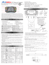
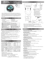
Reed Speed Sensor and Magnet:
1.This sensor is universal sensor for motorcycle, find a rotating part to install magnet (for example disk, sprocket or driveshaft) and
a location to install the sensor where it can be aligned to the magnet.
2.Align the center of the magnet to either of the sensor marking lines or the side of the sensor. The magnet must not travel down
the body of the sensor
3.Installing the sensor parallel to the vibration direction creates optional anti-vibration effect.
4.Make sure the gap between the magnet and the sensor is within 8mm.
RESET
RESET
MODE
RESET
2 Sec
+
+
MODE
MODE
MODE MODE
MODE
MODE
MODE
MODE
MODEMODE
MODE
2 sec
/