protech Sky Bike T0344 Instruction Manuel
- Category
- Remote controlled toys
- Type
- Instruction Manuel

Sky Bike - 1
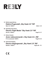
INSTRUCTION MANUEL
GEBRUIKSAANWIJZING
PLAN DE MONTAGE
ANLEITUNG
T0344
WARNING ! This R/C kit and
the model you will build is not
a toy.
LET OP ! Deze bouwdoos van
een radiobestuurd vliegtuig is
geen speelgoed.
ATTENTION ! Ce kit R/C d’un
avion n’est pas un jouet.
ACHTUNG ! Dieser Bausatz
von ferngesteurte model
ist kein Spielzeug.
version: 26/02/2002 • T0344

2 - Sky Bike
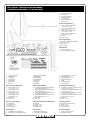
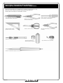
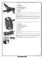
Kit content / Inhoud van de bouwdoos /
Installationssatzinhalt / Contenu de kit
1. Carbon tube fuselage
2. Main Wings
3. Horizontal Stabilizer
4. Vertical Stabilizer
5. Cockpit Seat
6. Instruction Manual
7. Decal Sheet
Under carriage parts bag
8. Carbon spar 3 mm diameter
27,3 cm long - 4 PCs
9. Carbon spar 3 mm diameter
21,4 cm long - 1 PC
10. Carbon spar 3 mm diameter
17,7 cm long - 3 PCs
11. Carbon spar 3 mm diameter
54,5 cm long - 2 PCs
12. Tail skid
13. Wheel - 2 PCs
Power unit parts bag
14. Gear box with firewall assembly
15. Propeller - 2 PCs
16. Nut - 3 PCs
17. Gear shaft
Plastic frames
A. Main aircraft parts
B. Controlhorns and kwiklinks
1. Carbon staaf romp
2. Hoofdvleugel
3. Hoogteroer
4. Richtingsroer
5. Zitje cockpit
6. Handleiding
7. Stickers
Delen voor het landingsgestel
8. Carbon staaf ø 3 mm
27,3 cm lang - 4 st
9. Carbon staaf ø 3 mm
21,4 cm lang - 1 st
10. Carbon staaf ø 3 mm
17,7 cm lang - 3 st
11. Carbon staaf ø 3 mm
54,5 cm lang - 2 st
12. Staartsteun
13. Wiel - 2 st
Delen voor de aandrijving
14. Aandrijving
15. Propeller - 2 st
16. Moer - 3 st
17. Aandrijf stang
Plastiek ramen
A. Hoofddelen van het vliegtuig
B. Stuurhoornen en snelkoppelingen
1. Des Carbongefäßrumpfs
2. Hauptflügel
3. Höhenleitwerk
4. Seitenleitwerk
5. Cockpit sitz
6. Anleitung
7. Abziehbild
Teilen des hauptfahrwerk
8. Carbonstab 3-Millimeter-Durchmesser
27.3 Zentimeter langes - 4 st
9. Carbonstab 3-Millimeter-Durchmesser
21.4 Zentimeter lang - 1 st
10. Carbonstab 3-Millimeter-Durchmesser
17.7 Zentimeter lang - 3 st
11. Carbonstab 3-Millimeter-Durchmesser
54.5 Zentimeter lang - 2 st
12. Hecksporn
13. Rad - 2 st
Stromversorgungseinheit zerteilt Beutel
14. Getriebe
15. Propeller - 2 st
16. Mutter - 3 st
17. Zahnradwelle
Plastik Rahme
A. Hauptteilen des flugzeug
B. Controlhorns und kwiklinks
1. Fuselage de tube de carbone
2. Ailes principales
3. Stabilisateur horizontal
4. Stabilisateur Vertical
5. Siège
6. Plan de montage
7. Décalcomanies
Pièces du train d’attérissage
8. Longeron de carbone diamètre de 3 mm
27.3 cm de long - 4 PCS
9. Longeron de carbone diamètre de 3 mm
21,4 cm de long - 1 PC
10. Longeron de carbone diamètre de 3 mm
17,7 cm de long - 3 PCS
11. Longeron de carbone diamètre de 3 mm
54,5 cm de long - 2 PCS
12. Béquille
13. Roue - 2 PCs
Pièces du réducteur
14. Réducteur de transmission
15. Hélice - 2 PCs
16. Ecrou - 3 PCs
17. Axe du réducteur
Trames en plastique
A. Pièce principale d’avion
B. Guignols et chapes

Sky Bike - 3
Plastic frames / Plastiek ramen /
Kunststoff Rahmen / Cadres en plastique
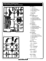
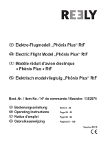
Plastic frames
A 1. Engine mount
2. Wing holder (1)
3. Wing holder (2)
4. Link for undercarriage
5. Push rod holder (middle)
6a. Vertical stabilizer mount (front)
6b. Vertical stabilizer mount (back)
7. Three-Axis joint (R)
8. Three-Axis joint (L)
9a. Wheel stopper
9b. Wheel stopper
10. Battery holder
11. Retainer
A
B
1
2
3
4
5
6a
6b
7
8
9a
9b
10
11
11
Plastic frames
B 1a. 1b. Kwiklink (1)
2a. 2b. Kwiklink (2)
3a. 3b. Control horn (1)
4a. 4b. Control horn (2)
5a. 5b. Servo horn
3b
3b
1b
1a
4b
4a
5b
5a
2b
2a
Plastieke ramen
A 1. Aandrijvings bevestiging
2. Vleugelbevestiging (1)
3. Vleugelbevestiging (2)
4. Landingsgestel bevestiging
5. Stuurstang houder (midden)
6a. Richtingsroer bevestiging (voor)
6b. Richtingsroer bevestiging (achter)
7. Samenvoegstukje voor drie assen (R)
8. Samenvoegstukje voor drie assen (L)
9a. Wielstop
9b. Wielstop
10. Batterij houder
11. Klemplaatje
Plastieke ramen
B 1a. 1b. Snelkoppeling (1)
2a. 2b. Snelkoppeling (2)
3a. 3b. Stuur hoorn (1)
4a. 4b. Stuur hoorn (2)
5a. 5b. Servo hoorn
Kunststoff Rahmen
B 1a. 1b. Gabelkopf (1)
2a. 2b. Gabelkopf (2)
3a. 3b. Ruderhorn (1)
4a. 4b. Ruderhorn (2)
5a. 5b. Servohorn
Cadre en plastique
B 1a. 1b. Chapes (1)
2a. 2b. Chapes (2)
3a. 3b. Guignol (1)
4a. 4b. Guignol (2)
5a. 5b. Levier de servo
Kunststoff Rahmen
A 1. Motorträger
2. Flügelhalterung (1)
3. Flügelhalterung (2)
4. Befestigung des Fahrgestells
5. Gestange Halterung(mittleres)
6a. Seitenleitwerkmontierung (vorn)
6b. Seitenleitwerkmontierung (rückseitige)
7. Drei Achsen verbindung (R)
8. Drei Achsen verbindung (L)
9a. Radstopper
9b. Radstopper
10. Batteriehalterung
11. Klemmschelle
Cadre en plastique
A 1. Bâti moteur
2. Support d'aile (1)
3. Support d'aile (1)
4. Lien pour le train d'atterrissage
5. Support de tige pousseur (moyen)
6a. Support de stabilisateur vertical (avant)
6b. Support de stabilisateur vertical (arrière)
7. Joint de Trois-Axes (R)
8. Joint de Trois-Axes (L)
9a. Arrêt de roue
9b. Arrêt de roue
10. Support de batterie
11. Plaquette

4 - Sky Bike
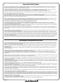
Important Safety Notes.
Be sure to read right through the instructions covering assembly and operation of your model before you attempt to operate it for the first time. You alone are
responsible for the safe operation of your radio-controlled model. Young people should only be permitted to build and fly these models under the instruction and
supervision of an adult who is aware of the hazards involved in this activity.
Use only matching polarised connectors. All cables, connectors and the battery if home-assembled must be insulated to prevent short circuits. Never attempt to
combine different types of plug and socket - e.g. tin-plated and gold-plated types - as such combinations are bound to be unreliable.
NC batteries are capable of holding and releasing enormous amounts of energy, and as such represent a constant hazard of explosion and fire.
We have no control over the way you build and operate your RC model aircraft, and for this reason we are obliged to deny all liability for accidents. All we can do is
point out the hazards and make sure you are aware of them.
If you need help, please enlist the aid of an experienced modeller, a model club or enrol at a model flying training school, Model shops and the specialist model
press are also good sources of information. The best course is always to join a club and fly at the approved model flying site.
Rubber bands deteriorate with age and become brittle. Replace them from time to time to maintain the safety and reliability of your model. Stretch all rubber bands
before use to check that they are still strong enough for their purpose.
Motors should only be run in the open air! The powerful suction of the propeller and the volume of air which it accelerates can easily lead to accidents in enclosed
spaces (e.g. pictures falling down, curtains sucked into the propeller). The model must be held securely by an assistant at all times.
Keep well clear of the rotational plane of propellers - don't stand in line with it or in front of it. You never know when some part may come loose and fly off at high
speed, hitting you or anybody else in the vicinity. Never touch the revolving propeller with any object.
There must be no chance of any object getting in the way of the propeller and preventing it rotating.
Take care with loose clothing such as scarves, loose shirts etc. Flapping cloth can easily be sucked into the area of the propeller and then get tangled in it.
If you start your motor when the model is standing on loose or sandy ground, the propeller will suck up sand and dust and hurl it around. and it could easily get in
your eyes. Wear protective goggles at such times.
Every time you intend to operate your model check carefully that it and everything attached to it (e.g. propeller, gearbox,RC components etc.) are in good condition
and undamaged. If you find a fault do not fly the model until you have corrected it.
Satisfy yourself that your frequency is vacant before you switch on. Radio interference caused by unknown sources can occur at any time without warning. If this
should happen, your model will be uncontrollable and completely unpredictable. Never leave your radio control system unguarded, as other people might pick it up
and try to use it.
Check that nothing is in the way of the propeller before you switch on the electric motor. Never attempt to stop the spinning propeller.Electric motors with a propeller
attached should only be run when installed securely.
lf you are to fly your model safely and avoid problems it is essential that you are aware of its position and attitude throughout each flight - so don't let it fly too far
away! lf you detect a control problem or interference during a flight,immediately land the model to prevent a potential accident Note that the transmitter throttle stick
must be set to the OFF (motor stopped) position before you switch on the power system. To avoid the electric motor starting unexpectedly, switch on the transmitter
first. then the receiving system. Use the reverse sequence when switching off: receiver first, then the transmitter. Check that the control surfaces move in the correct
"sense" when you operate the sticks.
Please don't misunderstand the purpose of these notes. We only want to make you aware of the many dangers and hazards which can arise if you lack knowledge
and experience, or work carelessly or irresponsibly. If you take reasonable care model flying is a highly creative, instructive, enjoyable and relaxing pastime.
Belangrijke Veiligheidsinstructies
Lees de instructies betreffende montage en werking van je model vooraleer u het de eerste maal in gebruik neemt. U alleen bent verantwoordelijk voor de veilige
werking van uw radiobestuurd model. Kinderen zijn enkel toegestaan om deze modellen te bouwen en te vliegen onder het toeziend oog van een volwassene, die
zich bewust is van de gevaren die dit met zich meebrengt.
Gebruik enkel passende gepolariseerde verbindingsstukken. Alle kabels, verbindingsstukken en de batterij, indien deze zelf samengesteld is, moeten geïsoleerd
worden om kortsluiting te voorkomen. Poog nooit verschillende types van pluggen en contacten te kombineren (vb.tin-en goudcontacten), daar zulke combinaties
onbetrouwbaar zijn.
NC-batterijen zijn geschikt om enorme hoeveelheden energie vast te houden en vrij te geven. Zodoende vertegenwoordigt een batterij een constant risico op
explosie en brandgevaar.
Wij hebben geen controle over de manier waarop u het RC-vliegtuig bouwt en gebruikt. Daarom zijn wij verplicht om alle aansprakelijkheid voor ongevallen van de
hand te wijzen. Het enige dat in onze mogelijkheden ligt is u te waarschuwen voor de risico’s.
Als u hulp nodig heeft, roep dan de bijstand van een ervaren modelbouwer of een modelbouwclub in, of schrijf u in bij een modelvliegclub. Modelshops en de
gespecialiseerde pers zijn eveneens een geschikte bron van informatie. De beste les is echter zich aan te sluiten bij een club en te vliegen op de goedgekeurde
vliegplaatsen.
Rubber elastieken verslijten met het gebruiken en worden broos. Vervang ze tijdig, zodoende stelt u de veiligheid en de betrouwbaarheid van uw model veilig. Span
alle rubber elastieken op vooraleer u ze gebruikt om te controleren of ze nog sterk genoeg zijn.
Motoren mogen enkel buiten in openlucht lopen! De sterke zuigkracht van de propeller en de luchtverplaatsing die deze veroorzaakt, kan in kleine ruimten makkelijk
een ongeval tot gevolg hebben (vb. schilderijen die naar beneden vallen, een gordijn dat in de propeller gezogen wordt). Het model moet steeds stevig worden
vastgehouden door een helper.
Houdt de rotatiebaan van een propeller vrij, sta er nooit voor of in de lijn van de propeller. Er kan steeds een deel loskomen en met hoge snelheid wegvliegen, zodat
het uzelf of iemand anders in de omgeving kan verwonden. Raak de ronddraaiende propeller nooit met enig voorwerp aan. Vermijdt steeds dat welk voorwerp ook
het draaien van de propeller verhindert.
Pas op met losse kleding zoals sjaals, losse shirts, … Losse kleding kan makkelijk in de propeller gezogen worden.
Als u de motor start terwijl deze op losse of zanderige grond staat, zal de propeller het zand opzuigen en rondslingeren zodat het in je ogen kan komen. Draag dus
steeds een veiligheidsbril op zo’n momenten.
Controleer, elke keer als u een model wil gebruiken, zorgvuldig of het model en alles wat erbij hoort (vb. propeller, aandrijving, RC-onderdelen, …) in goede staat en
onbeschadigd is. Als u een fout bemerkt, vlieg dan niet met het model tot u de fout hebt opgelost.
Verzeker uzelf ervan dat de frequentie vrij is vooraleer u de zender aanzet. Radiostoringen veroorzaakt door vreemde bronnen kunnen op elk moment en zonder
waarschuwing voorkomen. Als dit gebeurt is je model oncontroleerbaar en volledig onvoorspelbaar. Laat uw radiobesturing nooit onbewaakt achter, andere mensen
zouden kunnen proberen het te gebruiken.
Controleer of er niets in de baan van de propeller is vooraleer u de electromotor aanzet. Probeer nooit de draaiende propeller te stoppen. Electromotoren verbonden
met een propeller mogen enkel lopen als deze veilig geïnstalleerd is.
Als u uw model veilig wil vliegen en u wil problemen vermijden, dan is het essentieel dat u zich bewust bent van zijn positite en hoogte tijdens iedere vlucht. Laat het
dus niet te ver weg vliegen ! Als u een controleprobleem of storingen ontdekt gedurende een vlucht, landt dan onmiddellijk om een mogelijk ongeval te voorkomen.
Bemerk dat de zenderstick voor de motorfunctie in de off-stand moet staan vooraleer u het systeem aanzet. Om te voorkomen dat de electromotor onverwacht start,
zet eerst de zender aan, later pas de ontvanger. Gebruik de omgekeerde volgorde bij het afzetten : eerst de ontvanger, dan de zender. Controleer of de roeren in de
juiste richting bewegen als u de sticks gebruikt.
Heb begrip voor het doel van deze opmerkingen. Wij willen u enkel opmerkzaam maken voor de vele gevaren en risico’s die zich kunnen voordoen als u kennis en
ervaring mist, nonchalant of onverantwoordelijk te werk gaat.
Als u redelijk zorg draagt, is modelvliegen een zeer creatieve, leerrijke, plezierige en ontspannende vrijetijdsbesteding.
Page is loading ...
Page is loading ...

Sky Bike - 7
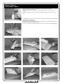
Decals / Decals /
Autocollants / Dekor
Om gemakkelijk te werken dient men alvorens het model samen te stellen de decals aan te brengen
op het hoogte en het richtingsroer.
Haal het folie van de decal (zie fig. 1).
Kleef de decals op de juiste positie en bevochtig de bovenzijde zeer grondig zonder het geheel te
bewegen. Verwijder de bovenlaag voorzichtig.
De decals op de vleugels op dezelfde wijze aanbrengen na het monteren van de vleugelbevestiging.
Fig. 1
Fig. 2
Fig. 3
Fig. 4
Fig. 5
Fig. 6
Fig. 7
Fig. 8
Fig. 9
Fig. 10
Fig. 11
To work more easely you must attach all the decals to the horizontal and vertical fin.
Take the foil from the decal (see fig. 1).
Place the decals in the wright position en moist the topside thoroughly. Carefully remove the
toplayer.
Use the same procedure for the decals on the wing after you have placed the carbon spars (see
page.

8 - Sky Bike
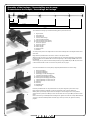
Assembly of the fuselage / Samenstelling van de romp /
Zusammenbau des Rumpfs / Assemblage du fuselage
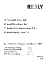
63mm
110mm
314mm
741mm
596mm
493mm
1
2
10
4
3
5
6a
6b
3 + 4
5
6a
6b
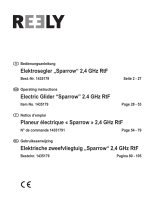
To assemble the fuselage you will need following plastic parts from frame A.
1. Engine mount
2. Wing holder (1)
3. Wing holder (2)
4. Link for undercarriage
5. Push rod holder (middle)
6a. Vertical stabilizer mount (front)
6b. Vertical stabilizer mount (back)
7. Three-Axis joint (R)
8. Three-Axis joint (L)
9a. Wheel stopper
9b. Wheel stopper
10. Battery holder
11. Retainer
You must put the parts in the wright order on the Carbon fuselage and on the wright distance from
each other.
Begin with the parts 3 and 4 at 314 mm as shown on the picture above.
After these two are put on you can place parts 2 at 63 mm and 1 at the beginning of the fuselage.
Followed by 5 at 493 mm, 6a at 596 mm from the beginning of the fuselage and 6b at the end of
the fuselage.
At this stage you only must mount the battery holder by using part 10 and part 11 (x2) from frame
A. Mount them with two screws as shown on the picture (10) on page 4.
Voor het samenstellen van de romp heb je volgende plastieke delen van raam A nodig.
1. Motor bevestiging
2. Vleugel bevestiging (1)
3. Vleugel bevestiging (2)
4. Bevestiging voor het landingsgestel
5. Stuurstang bevestiging (midden)
6a. Richtingsroer bevestiging (voorzijde)
6b. Richtingsroer bevestiging (achterzijde)
7. Samenvoegstukje voor drie assen (R)
8. Samenvoegstukje voor drie assen (L)
9a. Wielstop
9b. Wielstop
10. Batterijhouder
11. Klemplaatje
Plaats de plastieke delen om de juiste afstand en in de juiste volgorde op de Carbon romp.
Begin met het stukje 3 en stukje 4 op 314 mm te plaatsen zoals op de foto hierboven.
Nadien plaats je de stukjes 2 op 63 mm van het begin en 1 in het begin van de romp. Daarna
gevolgt door 5 op 493 mm en 6a op 45 mm van het einde van de romp en 6b op het einde van de
romp.
Men moet enkel nog de batterijhouder bevestigen door gebruik te maken van stukjes 10 en 11 (x2)
van raam A. Plaats de batterijhouder met twee vijsjes zoals op de foto (10) getoond wordt op
pagina 4.
Page is loading ...

10 - Sky Bike
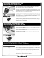
Fixing the seat / Samenstellen van het zitje /
Befestigung der Sitz / Montage du siège
Fixing the wheels / Bevestigen van de wielen /
Befestigung von die Räder / Montages des roues
Fixing the tailskid / Bevestigen van de staartsteun /
Befestigung von den Hecksporn / Montage de la béquille
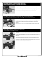
Assembling the undercarriage to the fuselage is a major part of completing this model. Before
assembly, check to recognize and prepare all the parts needed in this procedure. Be sure all the
carbon spars, the two (Right & Left) 3-Axis joints (A7) and seat (5) are in the correct position as
shown. Check to make sure all the carbon spars are snapped securely.
Het bevestigen van het landingsgestel is een hoofddeel voor de afwerking van dit model. Voor het
samenstellen moet je eerst nakijken of je alle onderdelen hebt. Let erop dat de carbon staven, in de
samenvoegstukjes voor drie assen (rechts en links) (A7) en het zitje (5) correct gepositioneerd zijn
zoals op de foto. Controleer of de carbon staven goed vast zitten.
Das Fahrgestell zum Rumpf zusammenzubauen ist ein größter Teil des bauen dieses Modells. Vor
Anfang überprüfen Sie, um alle Teile zu erkennen und vorzubereiten, die in dieser Prozedur benötigt
werden. Seien Sie sicher, daß alle Carbonstaben, die zwei (rechtes und linkes) 3-Achse
Verbindungen (A7) und der Sitz (5) in der richtigen Position sind, wie gezeigt. Überprüfen Sie daß
alle Carbonstaben sicher befestigd werden.
Assembler le train d'atterrissage au fuselage est une partie majeure de terminer ce modèle. Avant
assemblage, contrôlez pour identifier et préparer toutes les pièces nécessaires dans ce procédé.
Soyez sûr que tous les longerons de carbone, les deux joint de trois-axes (droit et gauche) (A7) et le
siège (5) sont en position correcte comme montrés. Contrôlez pour s'assurer que tous les
longerons de carbone sont casés solidement.
Check that the wheel stoppers (A9a,b) are snapped securely on the carbon spar (10) to prevent the
wheel from coming off the airplane while taxiing.
Controleer of de wielstoppen (A9a,b) goed vastzitten op de carbon staven (10) om te vermijden dat
de wielen los komen tijdens het taxiën.
Prüfen Sie ob die Radstopper (A9a, b) sicher auf das Carbongestange (10) gesetzt werden, um zu
verhindern das das Rad abkommt beim fahren.
Contrôlez que les arrêts de roue (A9a, b) sont fixés solidement sur le longeron de carbone (10)
pour empêcher la roue de se dégager.
To assemble the tail skid, simply push it into the slot as shown. The undercarriage and tail skid can
be removed for lighter weight, lower drag and better performance. But, be careful when landing.
Om de staartsteun te bevestigen moet je simpel weg de staartsteun in het bevestigingsstukje
duwen. Het landingsgestel en de staartsteun kunnen verwijderd worden voor een lagere weerstand
en voor een betere prestatie. Maar dan wel voorzichtig zijn bij het landen.
Um den Hecksporn zusammenzubauen, drücken Sie ihn einfach in den Schlitz, wie gezeigt. Das
Fahrgestell- und Hecksporn kann für weniger Gewicht, niedrigere Gegenkraft und bessere Leistung
gelöscht werden. Aber, geben Sie bei der Landung acht.
Pour assembler la béquille, poussez simplement la dans la fente comme montrée. Le train
d'attérrissage et la béquille peuvent être retiré pour un poids plus léger, une drague inférieure et une
meilleure performance. Mais, fassiez attention pour l'attérrissage.
Page is loading ...

12 - Sky Bike
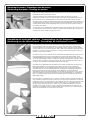
Assembling the vertical stabilizer / Samenstellen van het richtingsroer /
Montierung von das Seitenruder / Montage du gouvernail de direction
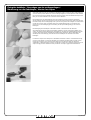
Cut off the stabilizer fin with a knife. Then stick them back togheter using tape at both sides. For
better movement you must press with a ruler between the stabilizer and the stabilizer fin until the
tape at the bottom sticks to the tape at the top. Cut off any unnessecary tape. Carefully slide the
vertical fin stabilizer into the slot located at the rear top of the fuselage as shown on the picture.
When satisfied that the vertical fin is properly aligned, install clear tape where the fuselage meets
the fin.
Snij met een mes het roer los. Plak het daarna met kleefband aan beide zijde terug samen. Voor een
beter bewegingsvrijheid moet je tussen de kleefband met een lat tegen elkaar drukken. Snij de
overtollige kleefband weg. Plaats nu voorzichtig het richtingsroer in de bevestigingsstukjes op de
romp zoals op de foto. Als het roer goed gepositioneerd is moet je met kleefband de delen die
samenkomen met de romp vastplakken.
Page is loading ...

14 - Sky Bike
Fixing the control horns / Bevestigen van de stuurhoornen /
Montierung des Ruderhornen / Montage des guignols
For mounting the control horns in the vertical and horizontal stabilizer fin you need following plastic
parts of frame B:
3a. 3b. Control horn (1)
4a. 4b. Control horn (2)
Put the control horn true the stabilizer fin. Cutting a little slit in the stabilizer fin will make the
installation easy. You can clip on the fixing part of the control horn at the back of the stabilizer fin.
Press it firmly into the stabilizer fin. Make sure you have put the control horn in the right position as
shown on the picture. One in the vertical fin facing left when you are in front of the airplane and the
other one down on the horizontal fin.
Voor het bevestigen van de stuurhoornen in het richtingsroer en het hoogteroer heb je volgende
plastieke delen nodig uit raam B:
3a. 3b. Stuurhoorn (1)
4a. 4b. Stuurhoorn (2)
Druk de hoorn door het roer. Door eerst met een mes een klein slipje te maken zal het monteren veel
makkelijker gaan. Je kan nu het bevestigingsstukje van de hoorn aan de andere kant van het roer op
de hoorn drukken. Druk dit goed vast in het roer. Zorg ervoor dat je de hoorn in de juiste richting
positioneerd zoals op de foto. In het richtingsroer naar links gericht als u voor het vliegtuig staat en
voor het hoogteroer naar onder gericht.
Für die Montierung der Steuerhorne in das Seitenruder und das Höhenruder benötigen Sie folgende
Plastikteile von Rahme B:
3a. 3b. Ruderhorn (1)
4a. 4b. Ruderhorn (2)
Drucken Sie das Steuerhorn durch das Ruder. Durch einen Schlitz zu machen ist dies einfach. Sie
können dem Befestigungsteil des Steuerhorns an die andere Seite des Ruder befestigen durch an
zu drucken. Überprüfen Sie, das Steuerhorn in die rechte Position eingesetzt zu haben, wie gezeigt
worden auf der Abbildung. Ein in das Seitenruder, die nach links gegenüberstellt, wenn Sie vor dem
Flugzeug sind und dem anderen unten auf das Höhenruder.
Pour monter les guignols dans l'aileron de stabilisateur vertical et horizontal vous avez besoin des
parties en plastique suivantes de la cadre B:
3a. 3b. Guignol (1)
4a. 4b. Guignol (2)
Mettez le guignol dans l'aileron de stabilisateur. La coupure fendu dans l'aileron de stabilisateur
rendra l'installation facile. Appuyez-le fermement dans l'aileron de stabilisateur. Assurez vous
d’avoir mis le guignol dans la bonne position comme montré sur l'image. Un dans l'aileron vertical
faisant face à gauche quand vous êtes devant l'avion et l'autre vers le bas sur l'aileron horizontal.
Page is loading ...

16 - Sky Bike
Fixing the pushrods / Plaatsen van de stuurstangen /
Montierung des Stosselstange / Montage des tiges pousseur
The push rod should be bent on one end with a Z-bender. This side should go into the servo horn as
shown on the picture. Put the push rod in the holes of the pastic parts along the fuselage. One for
the vertical stabilizer and one for the horizontal stabilizer.
De stuurstangen langs één zijde met een Z-bender plooien. Dit dient voor bevestiging inde servo
hoorn zoals op de foto. De stuurstang door de gaatjes voeren in de bevestigingsstukjes langs de
romp. Eén voor het richtingsroer en één voor het hoogteroer.
Der Stosselstange sollte an einem Ende mit einem Z-Bieger verbogen werden. Diese Seite sollte in
das Servohorn einrasten, wie auf der Abbildung gezeigt. Setzen Sie die Stosselstange in die
Bohrungen der pastic Teile entlang dem Rumpf ein. Ein für das Seitenleitwerk und eins für das
Höhenleitwerk.
La tige pousseur devrait être dépliée sur une extrémité avec une Z-cintreuse. Ce côté devrait entrer
dans le guignol de servo comme montré sur l'image. Mettez la tige pousseur dans les trous des
parties pastiques le long du fuselage. Une pour le stabilisateur vertical et une pour le stabilisateur
horizontal.
Page is loading ...

18 - Sky Bike
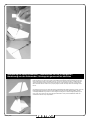
Placing the wing / Plaatsen van de vleugel /
Montierung des Haupt-Flügel / Placer l’aile principale
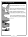
For placing the carbon wing spars you can stick tape to one side of the wing as shown on the
picture. Now you must place the carbon spar on the tape against the cut-out off the wing. Pull hte
tape back on to the wing to secure the carbon spar. You have to do this four times for each of the
carbon spars. While installing the wing on the fuselage, pay special attention to keep the two
carbon wing spars perfectly parallel and going into the slots at the same time. (Leading [front] edge:
large upper slots, Trailing [rear] edge: lower slots) Follow the same procedure to install the other
wing. Be sure the wing spars are inserted all the way in to the slots.
Voor het bevestigen van de carbon vleugelstaven kan je best eerst een stuk kleefband aan één zijde
van de vleugel plakken. Nu moet je de carbon staaf plaatsen tegen de uitsnijding in de vleugel. Trek
de kleefband over de carbon staaf op de andere zijde van de vleugel. Dit herhaal je voor elke
carbon staaf (x4). Als je de vleugel nu bevestigd op de romp moet je er op letten dat de twee carbon
staven perfect parallel zijn en gelijktijdig in de bevestigingsstukjes geduwd worden. (Neuslijst [voor]:
in het grootte bevestigingsstuk, de achterlijst [achter]: in het onderste bevestigingsstukje. Herhaal
deze procedure voor de installatie van de andere vleugel. Zorg ervoor dat de vleugeldelen volledig in
de bevestigingsstukjes geduwd zijn.
Für das Plazieren der Carbonstangen können Sie Klebeband an einer Seite des Flügels haften, wie
gezeigt auf der Abbildung. Jetzt müssen Sie die Carbonstange auf das Klebeband gegen den
Ausschnitt vom Flügel plazieren. Ziehen Sie den Klebeband zum Flügel zurück, um die
Carbonstange zu sichern. Sie müssen dies viermal für jede der Carbonstangen tun. Beim Installieren
des Flügels auf den Rumpf, zahlen Sie besondere Aufmerksamkeit, um die zwei Carbonstangen zu
halten tadellos parallel und in die Schlitze gleichzeitig einsteigen. (führender Rand [ vorderer ]: große
obere Schlitze, schleppender Rand [ hinterer ]: unterere Schlitze). Folgen der gleichen Prozedur, um
den anderen Flügel zu installieren. Seien Sie sicher, daß die Carbonstangen vollständig innen zu den
Schlitzen eingesetzt werden.
Pour placer les longerons d'aile de carbone vous pouvez coller la bande adhésive à un côté de l'aile
comme montré sur l'image. Maintenant vous devez placer le longeron de carbone sur la bande
contre le coupe-circuit outre de l'aile. Retirez la bande en fonction à l'aile pour fixer le longeron de
carbone. Vous devez faire ceci quatre fois pour chacun des longerons de carbone. Tout en installant
l'aile sur le fuselage, prêtez une particulière attention pour maintenir les deux longerons d'aile de
carbone parfaitement parallèles et en entrant dans les fentes en même temps. (bord principal [
avant ]: grandes fentes supérieures, bord de remorquage [ arrière ]: abaissez les fentes) Suivez le
même procédé pour installer l'autre aile. Soyez sûr que les longerons d'aile sont insérés toute la
voie dedans aux fentes.

Sky Bike - 19
Final check / Laatste controle /
Letzte Überprüfung / Contrôle final
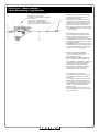
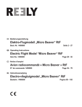
1. After the aircraft is assembled completely,
check to be sure that all the parts are
snapped together securely.
2. The correct C.G. (Center of Gravity) of the
“Sky Bike” is located ± 121,6 mm from the
leading edges of the main wing. By moving
battery pack forward or backward you can
adjust the correct balance of the aircraft.
3. When removing the undercarriage assembly
for a better performance, be sure to re-adjust
C.G. before flying.
C.G. location: ± 121,6 mm from the
leading edge of main wings.
Locatie Z.P.: ± 121,6 mm van de neuslijst
van de vleugel.
S.P.-Standort: ± 121.6 Millimeter vom
führenden Rand der Hauptflügel.
LocationC.G.: ± 121.6 millimètres à partir
des principaux bords de l'aile principale
1. Na het afwerken van het vliegtuig moet je
controleren dat alle delen goed vast zitten.
2. Het Z.P. (zwaartepunt) van de “Sky Bike” is
op ± 121,6 mm van de neuslijst van de
vleugel gelegen. Door de batterij naar voor of
naar achter te verplaatsen kan je het Z.P. van
het vliegtuig aanpassen.
3. Het landingsgestel en de staartsteun kunnen
verwijderd worden voor een lagere weerstand
en voor een betere prestatie. Pas de ligging
van het Z.P. aan voor u gaat vliegen.
1. Nachdem das Flugzeug vollständig
zusammengebaut ist, überprüfen Sie, um
sicher zu sein, daß alle Teile sicher
zusammen gebaut werden.
2. Das korrekte S.P. (Schwerpunkt) des Sky
Bikes ist lokalisiert ± 121.6 Millimeter von
den nasenleiste des Hauptflügels. Indem Sie
der Batteriesatz vorwärts oder rückwärts
verschieben, können Sie die korrekte
Abgleichung des Flugzeuges justieren.
3. Wenn Sie das Fahrgestell für eine bessere
Leistung löschen, seien Sie sicher, S.P.
nachzuregulieren, bevor Sie fliegen.
1. Après que l'avion soit assemblé
complètement, contrôlez pour être sûr que
toutes les pièces sont casées ensemble
solidement.
2. Le C.G. (centre de la gravité) correct du Sky
Bike est localisé ± 121.6 millimètres à partir
du bord d’attaque de l'aile principale. En
faisant avancer le paquet de batterie ou vers
l'arrière vous pouvez ajuster l'équilibre
correct de l'avion.
3. En retirant le train d'atterrissage pour une
meilleure performance, soyez sûr de rajuster
C.G. avant de voler.

20 - Sky Bike
© Copyright PROTECH
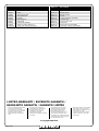
LIMITED WARRANTY / BEPERKTE GARANTIE /
BEGRENZTE GARANTIE / GARANTIE LIMITÉE
• Your kit is warranted against defects
in material and workmanship.
• This warranty does not apply to any
component parts, which have been
improperly installed, handled,
abused, damaged, modified and
used.
• De kit heeft een garantie voor
materiaalfouten en fabrieksfouten.
• Deze garantie geldt niet voor
onderdelen die niet goed zijn
geïnstalleerd, behandeld,
mishandeld, beschadigd, aangepast
en gebruikt.
• Ihr Installationssatz wird gegen
Defekte im Material und in der
Kunstfertigkeit gewährleistet.
•
Diese Garantie trifft nicht auf
irgendwelche Bestandteile zu, die
unsachgemäß installiert worden,
angefaßt worden, mißbraucht worden,
beschädigt worden, geändert worden
und benutzt worden sind.
• Votre kit est garanti contre les défauts
de matériaux et de main d’oeuvre
• Cette garantie ne s’applique pas aux
composants qui ont été
incorrectement montés, manipulés,
modifiés et utilisés ou qui ont été
endommagés.
Order nr Description
T0344.1 Propeller
T0344.2 Motor
T0344.3 Motor pinion 10T
T0344.4 Gear shaft 56T
T0344.5 Firewall
T0344.6 Main wing set
T0344.7 Vertical fin
T0344.8 Horizontal stabilizer
T0344.9 All 3mm carbon sticks set
T0344.10 3 axis joint undercarrage pair
Order nr Description
T0344.11 Tail skid
T0344.12 Wheels (pair)
T0344.13 Wheel stopper
T0344.14 Decals
T0344.15 Carbon fuselage assembly
T0344.16 Cockpit seat
T0344.17 Control unit cover
T0344.18 Push rods
T0344.19 Motor gear box assembly
T0344.20 Clevisses + Servo control horn
-
 1
1
-
 2
2
-
 3
3
-
 4
4
-
 5
5
-
 6
6
-
 7
7
-
 8
8
-
 9
9
-
 10
10
-
 11
11
-
 12
12
-
 13
13
-
 14
14
-
 15
15
-
 16
16
-
 17
17
-
 18
18
-
 19
19
-
 20
20


protech Sky Bike T0344 Instruction Manuel
- Category
- Remote controlled toys
- Type
- Instruction Manuel
Ask a question and I''ll find the answer in the document
Finding information in a document is now easier with AI
in other languages
- français: protech Sky Bike T0344
- Deutsch: protech Sky Bike T0344
- Nederlands: protech Sky Bike T0344
Related papers
Other documents
-
 Hoopo Protector Mounting User guide
-
 Case It/BMI Baby Toy 206 User manual
-
 Fuego T0375 User manual
-
Kmart 42954606 User manual
-
 Reely 1542913 Operating instructions
-
 Reely 1302975 Operating instructions
-
 Reely 1082714 Operating instructions
-
 Reely 1490800 Operating instructions
-
 Reely 1435179 Operating instructions
-
Sterling XXX10-80 User manual


