Page is loading ...

CLW-DIMEX-E
Cameo
®
Express Wireless In-Wall Dimmer, 120 V
Installation and Operation Guide
Changing the Button Assemblies
The button assembly can be removed and replaced with other button assemblies. To
change the button assembly:
1. Remove the button assembly by squeezing the sides of the bezel near the bezel
snaps.
6. While holding the program button, press each of the installed buttons in the new
layout. The LED next to the pressed button lights.
NOTE: If the rocker switch is installed, press the top and bottom of the rocker.
7. After all of the buttons have been pressed, release the program button to save the
settings.
NOTE: Changing the button conguration alters the device’s behavior. Refer to
“Default Button Functions” for details.
Multigang Installation
In multigang installations, several devices are grouped horizontally in one electrical box.
For a smooth appearance, a one-piece multigang faceplate (not supplied) can be
installed.
NOTE: When installing into a multigang box, do not fully tighten the devices to the box
until the faceplate has been aligned.
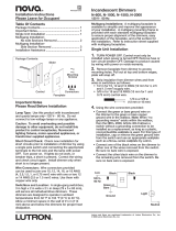
The load capacity for each device in the electrical box must be derated. Refer to the
diagrams for derating information.
NOTE: VA ratings are for input power to the transformer. If the input power
requirements of the transformer are unknown, use the bulb’s wattage rating to
determine the proper rating.
Derating Information for CLW-DIMEX-E Dimmers
Description
The Crestron
®
CLW-DIMEX-E is a Cameo
®
Express wireless in-wall dimmer that features
eld-replaceable and engravable buttons that can be congured for various button
layouts. The Cameo Express line makes it possible to bring controlled lighting to every
room in the home or ofce. Wireless inNET EX
®
communication technology brings
proven reliability to the CLW-DIMEX-E.
CLW-DIMEX-E Specications
Important Notes
WARNING: To avoid re, shock, or death, turn off the power at the circuit breaker or
fuse and test that the power is off before wiring!
WARNING: New installations should be checked for short circuits prior to installing a
CLW-DIMEX-E dimmer. With the power off, close the circuit and restore the power. If
the lights do not work or a breaker trips, check and correct the wiring or xture (if
necessary). Install the dimmer only when the short is no longer present. The warranty is
void if the dimmer is installed and operated with a shorted load.
CAUTION: TO REDUCE THE RISK OF OVERHEATING AND POSSIBLE DAMAGE TO
OTHER EQUIPMENT, DO NOT INSTALL TO CONTROL A RECEPTACLE, A MOTOR
OPERATED APPLIANCE, A FLUORESCENT LIGHTING FIXTURE OR A
TRANSFORMER SUPPLIED APPLIANCE.
ATTENTION: GRADATEURS COMMANDANT UN BALLAST-AFIN DE RÉDUIRE LE
RISQUE DE SURCHAUFFE ET LA POSSIBILITÉ D’ENDOMMAGEMENT À D’AUTRES
MATÉRIELS, NE PAS INSTALLER POUR COMMANDER UNE PRISE, UN APPAREIL
D’ÉCLAIRAGE FLUORESCENT, UN APPAREIL OPÉRÉ DE MOTEUR OU UN
APPAREIL ALIMENTÉ PAR UN TRANSFORMATEUR.
NOTES: Observe the following points:
• Installation: This product should be installed by a licensed electrician.
• Codes: Install in accordance with all local and national electrical codes.
• Wiring: Use copper wire only. For supply connections, use wires rated for at least
75°C.
• Lamp Type: For use with permanently installed incandescent, magnetic low
voltage, or tungsten-halogen.
• Temperature: For use where temperatures are between 32° and 104°F
(0° and 40°C).
• Electrical Boxes: Devices mount in standard electrical boxes. For easy installation,
Crestron recommends using 3-1/2" deep electrical boxes. Several devices can be
installed in one electrical box (multigang). This requires derating of the dimming
device. For a smooth appearance, one-piece multigang faceplates (not supplied)
can be installed.
• Switches: Mechanical 3- or 4-way switches will not work with CLW-DIMEX-E
dimmers.
• Spacing: If mounting one device above another, leave at least 4-1/2" vertical space
between them.
Additional Resources
Visit the product page on the Crestron website (www.crestron.com)
for additional information and the latest rmware updates. Use a QR
reader application on your mobile device to scan the QR image.
* Derating applies for multigang installations. Refer to “Multigang Installation” for more information.
• Low-Voltage Applications: Use with core and coil (magnetic) low-voltage
transformers only. Do not use any solid-state electronic low voltage transformers.
Operation of a low-voltage circuit with all lamps inoperative or removed may result
in current ow in excess of normal levels. To avoid transformer overheating and
premature transformer failure, please observe the following points:
> Do not operate low-voltage circuits without operative lamps in place.
> Replace burned-out lamps as quickly as possible.
> Use transformers that incorporate thermal-protection or fuse-ransformer primary
windings to prevent transformer failure due to overcurrent.
Line
120 V ~
White
Black
White
Black
Load
NEU
GND
DIM
HOT
White
Installation
WARNING: Turn off the power at the circuit breaker. Installing with the power on can
result in serious personal injury and damage to the device.
The following describes the installation of a CLW-DIMEX-E dimmer:
1. Turn the power off at the circuit breaker.
2. Wire the device as shown in the diagram.
NOTE: The dimmer can operate with or without a connection to a neutral wire.
NOTE: Switch mode requires connection to a neutral wire.
Make Connections to the CLW-DIMEX-E.
No
Yes
Do not insert the wires behind the screw head.
Insert the wires into the wire entry holes.
NOTE: For optimal performance, the neutral should be connected. If the neutral
is not connected, the minimum required load is 50 W.
3. Push all power wires back into the electrical box, and fasten the device to the
electrical box with the provided screws.
NOTE: Use care when placing the device in the electrical box. Pinched wires
may cause a short circuit.
4. Attach the decorative faceplate.
5. Ensure that all buttons, including the program button and air-gap switch, actuate
without sticking.
NOTE: To operate the device in Switch mode, follow the instructions in
“Switching Between Dim Mode and Switch Mode” before restoring power.
6. Restore the power at the circuit breaker.
Gently spread the
frame apart to insert
the buttons.
Gently spread the
frame apart to remove
the buttons.
Squeeze at the
arrow points and
pull to remove the
button assembly.
NOTE: When the button assembly is removed, power disconnects from the
internal electronics and the connected loads. Power is still supplied to the HOT
terminal.
2. Remove the button from the front of the button assembly.
3. Insert the new buttons through the front of the bezel and snap them into place.
Ensure that the LED strip is on the left side.
4. Attach the button assembly to the device. Ensure that the LED strip is on the left
side.
5. Once power has been restored, press and hold the program button.
After 5 seconds, the LEDs associated with the old button layout begin to ash.
Continue to hold the button and proceed to step 6.
Steps 5 through 7 are illustrated below.
Step 5:
Press and hold
the program
button.
Step 7:
Release the
program button
to save the
settings.
Step 6:
Tap each of the
installed buttons
on the device.
750 VA
600 VA 600 VA
600 VA 400 VA
600 VA
Switching Between Dim Mode and Switch Mode
The CLW-DIMEX-E is capable of operating in Switch mode. Toggling between Dim and
Switch mode is useful if the load is not dimmable or if it is preferred not to have the load
dimmed. To toggle between Dim and Switch modes:
1. Open the air-gap switch as described in “Disconnecting the Power.”
2. While the power is off, press and hold the top and bottom button caps (regardless
of button conguration) simultaneously while closing the air-gap switch.
3. After 5 seconds, the top LED will blink three times to indicate Dim mode or ve
times to indicate Switch mode.
4. To commit the new setting, release the buttons within the next 5 seconds.
Operation
NOTE: Before using the CLW-DIMEX-E, ensure that the device is using the latest
rmware. Check for the latest rmware for the CLW-DIMEX-E at
www.crestron.com/rmware. Firmware is loaded onto the device using Crestron
Toolbox™.
NOTE: The device may be warm to the touch during operation. This is normal.
Basic Operation
The operations described in this guide assume that the CLW-DIMEX-E is operating in
Local mode (without the use of a control system). The device can also operate in Remote
mode, in which button behavior is dictated entirely by the control system program. The
CLW-DIMEX-E is shipped with a rocker switch already installed. In this conguration, the
unit functions as described below.
Press to turn on the load.
Press and hold to raise the light level.
Press to turn off the light load.
Press and hold to lower the light level.
The LEDs indicate the
load level. When all
loads are off, the top
LED remains dimly lit
to act as a nightlight.
In Switch mode, the
top LED indicates the
on or off status only.
All other LEDs are off.
SPECIFICATION DETAILS
Power Requirements 120 Vac, 60 Hz, line power
Load Ratings
Incandescent/
Tungsten Halogen
750 W*
Magnetic Low
Voltage
750 VA/750 W*
Minimum Load 25 W (with a neutral connected);
50 W (without a neutral connected)
Environmental
Temperature 32° to 104°F (0° to 40°C)
Humidity 10% to 90% RH (noncondensing)
Enclosure 1-gang mountable in a 3-1/2" deep electrical box;
Requires decorator style faceplate (sold separately)

The air-gap switch is
in the open position.
Push here to open
the air-gap switch.
Disconnecting the Power
Dsconnect the power to the dimmer and load by pushing on the air-gap switch.
NOTE: If the dimmer remains powered after the air-gap switch is opened, the HOT
and DIM terminals have been connected in reverse. Turn off the power at the circuit
breaker or fuse and adjust the connections.
NOTE: When the button assembly is removed, power disconnects from the internal
electronics and the connected loads. The power is still supplied to the HOT terminal.
For instructions on removing the button assembly, refer to “Changing the Button
Assemblies.”
Setting the Preset Levels
The CLW-DIMEX-E can recall and store up to three presets depending on the installed
button conguration.
To set a preset level:
1. Adjust the light level to the desired level.
2. Enter the Programming mode by quickly pressing the program button.
The LEDs blink beside the buttons capable of storing a preset.
NOTE: Programming mode is disabled when the load is off.
3. Press and hold the desired preset button for approximately 2 seconds.
4. Release the button to store the new level.
If a button is not pressed, the device exits Programming mode after approximately
5 seconds.
Step 3:
Hold the button to
store the new level.
Step 2:
Quickly press the
program button.
The LEDs blink to
indicate the buttons that
can be programmed.
Preset 1
Preset 2
Preset 3
Off
Default Button Functions
The gures below illustrate the default functions available for each physical button conguration and tap or hold actuation sequence.
Single Button Press
This product is Listed to applicable UL Standards and requirements by Underwriters Laboratories Inc.
Federal Communications Commission (FCC) Compliance Statement
This device complies with part 15 of the FCC Rules. Operation is subject to the following two
conditions: (1) This device may not cause harmful interference, and (2) this device must accept any
interference received, including interference that may cause undesired operation.
CAUTION: Changes or modications not expressly approved by the manufacturer responsible for
compliance could void the user’s authority to operate the equipment.
NOTE: This equipment has been tested and found to comply with the limits for a Class B digital
device, pursuant to part 15 of the FCC Rules. These limits are designed to provide reasonable
protection against harmful interference in a residential installation. This equipment generates, uses
and can radiate radio frequency energy and, if not installed and used in accordance with the
instructions, may cause harmful interference to radio communications. However, there is no guarantee
that interference will not occur in a particular installation.
Wireless Communications
The device connects to the Crestron network via the inNET EX communications protocol. Use the procedures outlined below to join or
leave an inNET EX network and to verify communications between the device and the control system.
Joining an inNET EX Network
Before a device can be used in a lighting system, it must rst join an inNET EX network. To join an inNET EX network, the device must
be acquired by an inNET EX gateway.
NOTE: A device can be acquired by only one gateway.
1. Put the inNET EX gateway into Acquire mode from the unit itself or from Crestron Toolbox. Refer to the gateway’s manual at
www.crestron.com/manuals for details.
NOTE: In an environment where multiple gateways are installed, only one gateway should be in Acquire mode at any time.
2. Put the device into Acquire mode:
a. Tap the top button three times, and then press and hold it down (tap-tap-tap-press+hold) until all of the LEDs on the device blink
once (this can take up to 10 seconds).
b. Release the button to start the acquire process. The top LED blinks slowly to show that the device is actively scanning the
inNET EX network.
• The top LED turns on for 5 seconds to show that the device has been successfully acquired by the infiNET EX network.
• The top LED blinks fast to indicate that the device was not successfully acquired by the infiNET EX network. Tap the top
button to acknowledge the failure. Ensure the gateway is in Acquire mode and within range before attempting the acquire
process again.
3. Once all devices have been acquired, take the gateway out of Acquire mode. Refer to the gateway’s manual for details.
Leaving an inNET EX Network
To leave an inNET EX network, put the device into Acquire mode, as described in “Joining an inNET EX Network” above, when no
gateway is in Acquire mode.
Verifying Communications Status
To check the communications status of the device, tap the top button three times, and then press and hold it down
(tap-tap-tap-press+hold) for up to 2 seconds. The top LED blinks to indicate the communications status. Refer to the following table for
details.
Troubleshooting
The following table provides corrective actions for possible trouble situations. If further assistance is required, please contact a Crestron
customer service representative.
CLW-DIMSWEX-E Troubleshooting
Crestron Electronics, Inc. Installation & Operation Guide - DOC. 6817F
15 Volvo Drive Rockleigh, NJ 07647 (2024288)
Tel: 888.CRESTRON 10.15
Fax: 201.767.7576 Specications subject to
www.crestron.com change without notice.
If this equipment does cause harmful interference to radio or television reception, which can be determined by
turning the equipment off and on, the user is encouraged to try to correct the interference by one or more of
the following measures:
• Reorient or relocate the receiving antenna.
• Increase the se paration between the equipment and receiver.
• Connect the equipment into an outlet on a circuit different from that to which the receiver is connected.
• Consult the dealer or an experienced radio/TV technician for help.
Industry Canada (IC) Compliance Statement
This device complies with Industry Canada license-exempt RSS standard(s). Operation is subject to the
following two conditions: (1) this device may not cause interference and (2) this device must accept any
interference, including interference that may cause undesired operation of the device. Under Industry Canada
regulations, this radio transmitter may only operate using an antenna of a type and maximum (or lesser) gain
approved for the transmitter by Industry Canada. To reduce potential radio interference to other users, the
antenna type and its gain should be so chosen that the equivalent isotropically radiated power (e.i.r.p.) is not
more than that necessary for successful communication.
Crestron, the Crestron logo, Cameo, Crestron Toolbox, inNET EX, and the inNET EX logo are either
trademarks or registered trademarks of Crestron Electronics, Inc. in the United States and/or other
countries. UL and the UL logo are either trademarks or registered trademarks of Underwriters
Laboratories, Inc. in the United States and/or other countries. Other trademarks, registered
trademarks, and trade names may be used in this document to refer to either the entities claiming the
marks and names or their products. Crestron disclaims any proprietary interest in the marks and
names of others. Crestron is not responsible for errors in typography or photography.
This document was written by the Technical Publications department at Crestron.
©2015 Crestron Electronics, Inc.
Double Button Press (Press twice within 1/2 a second.)
Fast Off Fast Off
Fast Off
Fast Off
Full On
Full On
Full On
Full On
Full On
Full On
Full On
Full On
Full On
Preset 1
Preset 1
Preset 1
Preset 1
Toggle
Preset 3
Preset 2
Preset 2
Preset 1
Preset 1
Toggle
Raise
Lower
Off
Raise
Lower
Off
Off
Off
Single Button Press and Hold (Hold for more than 1/2 a second.)
Raise Raise Raise
Raise
Lower
Lower
Lower
Lower
Lower
Lower
Raise
Raise
Industrie Canada (IC) Déclaration de conformité
Le présent appareil est conforme aux CNR d’Industrie Canada applicables aux appareils radio exempts
de licence. L’exploitation est autorisée aux deux conditions suivantes : (1) l’appareil ne doit pas produire
de brouillage, et (2) l’utilisateur de l’appareil doit accepter tout brouillage radioélectrique subi, même si
le brouillage est susceptible d’en compromettre le fonctionnement. Conformément à la réglementation
d’Industrie Canada, le présent émetteur radio peut fonctionner avec une antenne d’un type et d’un gain
maximal (ou inférieur) approuvé pour l’émetteur par Industrie Canada. Dans le but de réduire les risques
de brouillage radioélectrique à l’intention des autres utilisateurs, il faut choisir le type d’antenne et son
gain de sorte que la puissance isotrope rayonnée équivalente (p.i.r.e.) ne dépasse pas l’intensité
nécessaire à l’établissement d’une communication satisfaisante.
The product warranty can be found at www.crestron.com/warranty.
The specic patents that cover Crestron products are listed at patents.crestron.com.
Certain Crestron products contain open source software. For specic information, please visit
www.crestron.com/opensource.
LED COMMUNICATIONS STATUS
Turns on for 5 seconds The device is communicating with the control system.
Blinks three times The device is communicating with the gateway, but the gateway is not communicating with the control
system.
Blinks twice The device was previously joined to the network but is not communicating with the gateway.
Blinks once The device is not joined to the network.
TROUBLE POSSIBLE CAUSE(S) CORRECTIVE ACTION
The dimmer does not function. The dimmer is not receiving line
power.
Verify that the dimmer is properly connected to the
power line, and verify that the circuit breaker is closed.
The load is not operational. Verify that the load works and the air-gap switch is
closed.
The dimmer is in Remote mode. Check the program to determine or change the
operating mode.
No neutral connection exists, and all
attached lamps are burned out.
Connect the neutral and replace the burned-out lamps.
The dimmer does not dim. The dimmer is in Switch mode. Remove the power from the device. Reapply the power
and press and hold the top and bottom buttons for
5 seconds. If the LED blinks 3 times, the device is in
Dim mode; if it blinks 5 times, it is in Switch mode.
The dimmer remains powered
and air-gap switch is opened.
The HOT and DIM terminals are wired
in reverse.
Turn off the power at the circuit breaker or fuse and
adjust the connections.
The dimmer cycles off
occasionally when near full
brightness.
The load connected is less than 25 W. Increase the load on the circuit to at least 25 W.
A neutral wire is required for loads less than 50 W.
The load connected is less than 50 W. Connect the neutral to the dimmer.
/