Voyager
™
40 ARF
ALMOST READY-TO-FLY RADIO CONTROLLED MODEL AIRPLANE
WARRANTY
Tower Hobbies
®
guarantees this kit to be free from defects in both material and workmanship at the date of purchase. This warranty
does not cover any component parts damaged by use or modification. In no case shall Tower Hobbies’ liability exceed the original
cost of the purchased kit. Further, Tower Hobbies reserves the right to change or modify this warranty without notice.
In that Tower Hobbies has no control over the final assembly or material used for final assembly, no liability shall be assumed nor
accepted for any damage resulting from the use by the user of the final user-assembled product. By the act of using the user-assembled
product, the user accepts all resulting liability.
If the buyers are not prepared to accept the liability associated with the use of this product, they are advised to return this kit
immediately in new and unused condition to the place of purchase.
© Copyright 2002 V1.0
TOWZ1151 for TOWA2048
WINGSPAN: 59.5 in. [1510mm]
WING AREA: 580 in
2
[37.4 dm
2
]
WEIGHT: 4 lb. 14 oz. [2210 g]
WING LOADING: 19.4 oz/ft
2
[59 g/dm
2
]
LENGTH: 47.5 in. [1210mm]
RADIO: 4-channel (with four standard servos)
ENGINE: .40 – .46 cu. in. [6.5 – 7.5cc] two-stroke

Page
INTRODUCTION ....................................................................2
PRECAUTIONS ........................................................................2
SUGGESTED TOOLS & SUPPLIES ............................................2
ACCESSORIES REQUIRED TO COMPLETE
YOUR VOYAGER ARF ..............................................................3
ENGINE SELECTION................................................................3
COMMON ABBREVIATIONS ..................................................3
ORDERING REPLACEMENT PARTS ........................................3
METRIC/INCH RULER ............................................................3
PARTS LIST ..............................................................................4
HARDWARE AND PLASTIC BAG CONTENTS ........................4
WING ASSEMBLY ....................................................................5
FUSELAGE ASSEMBLY ..............................................................9
INSTALL THE LANDING GEAR..............................................11
ENGINE INSTALLATION ......................................................12
RADIO INSTALLATION ........................................................14
FINISHING UP THE AIRPLANE ............................................16
GET THE MODEL READY TO FLY ..........................................16
BALANCE YOUR MODEL ......................................................17
PREPARING TO FLY YOUR TOWER VOYAGER 40 ARF..........17
AMA SAFETY CODE (excerpt) ..............................................18
FLYING YOUR TOWER VOYAGER 40 ARF ............................19
Now that you have mastered the basics of R/C flight with your
primary trainer, you are ready to advance to the next higher
level...a level that will open the doors to aerobatics. With the
experience you’ve acquired with your trainer, along with the
Tower Hobbies Voyager
™
, you will be able to learn and master
the maneuvers that your club hot shots perform.
The Voyager, with its low mounted wing, rugged construction,
and heavy duty landing gear, will allow you to practice and
perfect any maneuver you desire. But don’t let its aerobatic
qualities put you off. The Voyager is also an extremely docile flier.
Thanks to its semi-symmetrical airfoil and light wing loading,
you’ll be able to “grease her in” every landing. Welcome to the
world of sport flying.
Protect Your Model, Yourself & Others
Follow This Important Safety Precaution
Your Tower Voyager is not a toy, but rather a sophisticated,
working model that functions very much like a full-size airplane.
Because of its realistic performance, the Tower Voyager, if not
assembled and operated correctly, could possibly cause injury to
yourself or spectators and damage property.
To make your R/C modeling experience totally enjoyable, we
recommend that you get experienced, knowledgeable help with
assembly and during your first flights. You’ll learn faster and
avoid risking your model before you’re truly ready to solo. Your
local hobby shop has information about flying clubs in your area
whose membership includes qualified instructors.
You can also contact the national Academy of Model Aeronautics
(AMA), which has more than 2,500 chartered clubs across the
country.
Through any one of them, instructor training programs and
insured newcomer training are available.
We recommend Great Planes
®
, Hobbico
®
and Tower brand glues
and accessories for your modeling needs.
❍ Great Planes Pro
™
Thin CA 2 oz. - GPMR6003
❍ Great Planes Pro 6-minute Epoxy - GPMR6045
❍ Great Planes Pro 30-minute Epoxy - GPMR6047
❍ Hand or Electric Drill
❍ Drill Bits: (1/16", 3/32", 1/8", 5/32", 11/64", 7/32", 1/4")
[1.5mm, 2.5mm, 3mm, 4mm, 4.5mm, 5.5mm, 6mm]
❍ Hobby Saw (X-Acto
®
Razor Saw)
❍ Hobby Knife, #11 Blades (TOWR1015)
❍ Pliers
❍ Screwdrivers (Phillips and Flat Blade) (HCAR1040)
❍ Flat File (or Similar Tool)
❍ T-Pins (Short – HCAR5100, Long – HCAR5200)
❍ String
❍ Dremel
®
Multi-Pro or Similar (Optional)
SUGGESTED TOOLS AND SUPPLIES
Academy of Model Aeronautics
5151 East Memorial Drive
Muncie. IN 47302-9252
Office: (765) 287-1256
Toll Free: (800) 435-9262
Fax: (765) 741-0057
or via the internet at: http//www.modelaircraft.org
READ THROUGH THIS INSTRUCTION BOOK FIRST. IT
CONTAINS IMPORTANT INFORMATION CONCERNING
THE ASSEMBLY AND USE OF THIS MODEL.
PRECAUTIONS
INTRODUCTION
TABLE OF CONTENTS
2

❍ 4-Channel Radio With 4 Servos
❍ (1) 6" Aileron Extension (HCAM2000)
❍ Engine; (See Engine Selection)
❍ Spare Glow Plugs (Tower R/C Long - TOWG1001)
❍ 3' Medium Fuel Tubing (GPMQ4131)
❍ 1/4" Latex Foam Rubber Padding (HCAQ1000)
A quality brand .40-size engine will be needed. Also a prop will
be required for the engine (follow the manufacturer’s
recommendations for appropriate sizes). We recommend the Top
Flite
®
Power Point
®
brand of props.
We recommend the following engines:
❍ Tower Hobbies .40 ABC (TOWG0040)
❍ Tower Hobbies .46 ABC (TOWG0146)
❍ O.S.
®
.40 LA (OSMG0040)
❍ O.S. .40 FX (OSMG0540)
❍ SuperTigre
®
GS-40 (SUPG0122)
Fuse = Fuselage
Stab = Horizontal Stabilizer
Fin = Vertical Fin
LE = Leading Edge
TE = Trailing Edge
LG = Landing Gear
Ply = Plywood
" = Inches
Replacement parts are available from Tower Hobbies for your
Tower Voyager. Our order assistance representatives are ready to
answer your questions or to place your order. Call us at (800)
637-6050 or see our website at:
www.
Replacement Parts
Wing Set – TOWA5090
Fuselage Set – TOWA5091
Tail Set – TOWA5092
Landing Gear Set – TOWA5093
Cowl – TOWA5094
ORDERING REPLACEMENT PARTS
COMMON ABBREVIATIONS
ENGINE SELECTION
ACCESSORIES REQUIRED TO COMPLETE
YOUR VOYAGER ARF
3

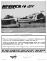
Before assembly match the parts in the above image to the parts in
the kit. Check off each part as it is located. If any parts are missing
or damaged, consult Tower Hobbies Order Assistance (see page 19
for phone numbers).
1 Fuselage
2 Left Wing Panel w/Aileron
3 Right Wing Panel w/Aileron
4 Transparent Canopy
5 Stabilizer/Elevator
6 Rudder/Fin
7 Main Landing Gear (2 pcs.)
8 Pushrods
9 Nose Landing Gear
10 70mm Foam Wheels (3)
11 Fiberglass Cowl
12 Adjustable Engine Mount
13 Complete 270cc Fuel Tank
14 Complete ABS Pilot Bust (2 pcs.)
15 Aileron Servo Tray Mounting Block
16 Wing Joiners (3 pcs.)
17 Aileron Servo Tray
18 Hardware Bag
19 Plastic Parts Bag
(2) 6" [152mm] Threaded One End Pushrods
(2) 36" [914mm] Threaded One End
Pushrods
(2) 36" [914mm] Outer Flexible Pushrod
(1) Nylon Steering Arm
(2) Adjustable Metal Engine Mount Parts
(2) 8mm x 8mm x 35mm Hard Balsa Sticks
(1) 2" Red Spinner
(4) Plastic Quick Links
(5) Plastic Clevises
(2) Plastic Control Horns
(2) Plastic Control Horn Backplates
(4) Nylon Landing Gear Straps
(5) Silicone Retainers
(14) Pre-cut Round CA Hinges
(1) Plastic Front Gear Attachment
(6) 4mm x 15mm Bolts
(2) 4mm x 35mm Bolts
(4) 4mm x 25mm Bolts
(7) 4mm Wheel Collars
(2) 4mm Flat Washer
(4) 2mm x 15mm Bolts
(4) 4mm Hex Nuts
(8) 3mm x 5mm Bolts
(2) Complete “EZ Type” Connectors
(4) 4mm Lock Washers
(8) 2mm x 10mm Screws With Built-in
Washer
(8) 2mm x 10mm Screws
(1) Decal Sheet
4
PARTS LIST
HARDWARE AND PLASTIC BAG CONTENTS
13
18
1
4
5
6
9
2
3
11
14
15
17
16
19
12
7
8
10

Special Note: It is suggested to charge your radio system before
starting to build. Following the manufacturer’s instructions,
connect your transmitter and receiver batteries to the system’s
charger. This way the radio will be ready when it is time to install
and test the radio components.
PREPARE THE WING JOINERS
❍ 1. Locate the three 1/8" [3mm] die-cut wing joiners. Arrange
the joiners in the same orientation as they will be glued together.
Sand off any bumps from the edges.
Note: Please read through the following two steps before mixing
any epoxy.
GLUE THE WING JOINERS
❍ 2. Mix approximately 1/4 oz. [7ml] of 30-minute epoxy using
a mixing stick and a cup. Apply an even coat of epoxy on both
sides of one joiner using a mixing stick or an epoxy brush. This
joiner will be the center joiner of the assembly. Apply a thin coat
on one side of each of the other two joiners. These will be on
either side of the center joiner. Quickly proceed through the
following two steps before the epoxy cures.
CLAMP THE WING JOINER
❍ 3. Use clothespins to clamp the wing joiners firmly together. If
any epoxy squeezes out, remove it using a paper towel
dampened with denatured alcohol. Make sure the joiners are
evenly lined up with each other. Set the joiner assembly aside
until the epoxy has fully cured.
MARK THE CENTERLINE OF THE JOINER
❍ 4. After the epoxy has cured, remove the clothespins and draw
a centerline on both sides of the plywood wing joiner as shown.
TEST FIT THE WING JOINER
❍ 5. Test fit the wing joiner in both wing panels by sliding the
joiner into the wing joiner pocket. The joiner should slide in with
little resistance up to the centerline that was drawn on the joiner.
If the fit is too tight, lightly sand the wing joiner to make it fit.
Caution: A snug fit of the joiner in the wing joiner pockets is
desired. Do not sand the joiner excessively.
WING ASSEMBLY
5

VIEWING THE WING DIHEDRAL
❍ 6. Pay close attention to the orientation of the wing joiner in
relation to the wing panel, creating the dihedral angle as shown.
TEST THE FIT OF THE WING PANELS
❍ 7. Test fit the wing panels together. They should fit flush against
each other without any gaps. If the wing panels do not fit together
tightly, sand the wing joiner or the wing roots lightly. With one of
the wing panels laying flat on a flat surface, the other wing
panel’s wing tip should be raised between 2" and 2-1/4" [51mm
to 57mm].
JOIN THE WING HALVES
❍ 8. Mix 1/2 oz. [14 ml] of 30-minute epoxy. Use a mixing stick
or epoxy brush to apply epoxy to both wing roots and to all sides
of the wing joiner. Apply the rest of the epoxy inside both wing
joiner pockets. Install the wing joiner in the wing joiner pockets
and press the wings together. The fit should be as tight as
possible. Use several strips of tape to hold the wing halves
together while the epoxy cures. Use a small clamp to clamp the
wing mounting tabs together.
REMOVE THE EXCESS EPOXY
❍ 9. Clean up any excess epoxy with paper towels dampened
with denatured alcohol. The dihedral angle is established by the
wing joiner and the angle of the wing roots. As long as the wing
roots fit together tightly, the dihedral angle will be correct.
APPLY THE WING CENTER-SECTION TAPE
❍ 10. Starting at the leading edge of the wing, apply the 1/2" x
11" [13 mm x 280 mm] white wing center-section tape on the
bottom wing center-section glue joint. A small amount of
pressure should be applied to make a smooth seam.
TRIM THE WING COVERING
❍ 11. Hold the aileron servo tray over the hole in the center
section of the wing. Outline the tray. Trim the covering and
6

enlarge the opening in the wing skin for the aileron servo. When
trimming the covering, be careful not to cut into the wood.
ASSEMBLE THE AILERON SERVO TRAY
❍ 12. Locate the two 5/16" x 5/16" x 1-3/8" [8mm x 8mm x
35mm] balsa aileron servo tray mounting blocks. Draw a
centerline on the mounting blocks. Glue the balsa aileron servo
mounting blocks onto the aileron servo tray using either 6-minute
epoxy or medium CA.
INSTALL THE AILERON SERVO TRAY
❍ 13. Test fit the tray on the wing. Sand the tray mounting blocks
until the tray sits flat against the wing. Glue the servo tray to the
wing using either medium CA or 6-minute epoxy.
PREPARE TO INSTALL THE AILERONS
❍ 14. Separate the ailerons from the wing by removing the tape
that holds them together.
PREPARE THE HINGE SLOTS
❍ 15. Drill a 3/32" [2.4 mm] hole in the center of each hinge slot
both in the wing’s trailing edge and in the ailerons. Use a sharp
#11 blade to clean up the slots and to cut a strip of covering from
the slots in the wing and aileron.
INSTALL THE AILERON HINGES
❍ 16. Insert the CA hinges in the wing’s trailing edge. Note that
the direction of the cut in the hinges is perpendicular to the hinge
line. Stick a pin through the center of the hinge near the cut. Test
fit the ailerons to the wing with the hinges. There should be a
small gap between the ailerons and the wing. Remove the
ailerons.
GLUE THE AILERON HINGES
❍ 17. Drop a small amount of 30-minute epoxy into the torque
rod’s holes in the ailerons. Re-install the ailerons and apply six
7

drops of thin CA to the top and bottom of each CA hinge. Do not
use accelerator. Let the CA fully harden and then test the hinges
by pulling on the aileron.
INSTALL THE AILERON CONTROL HORNS
❍ 18. Thread the aileron control horns into the torque rods until
they are positioned 3/4" [19mm] above the wing’s surface.
ASSEMBLE THE AILERON’S PUSHRODS
❍ 19. Locate two plastic clevises, two 6" [152mm] threaded one
end pushrods and two clevis retainers. Thread a clevis onto each
pushrod
about 18 full turns. Slide a clevis retainer partially onto
each
clevis.
INSTALL THE AILERON’S PUSHRODS
❍ 20. Attach the pushrods to the aileron control horns. Press the
forks of the clevises together until the pin snaps into the opposite
fork. Slide the clevis retainer onto the clevis.
INSTALL THE AILERON SERVO
❍ 21. Install the aileron servo on the aileron’s servo tray with the
hardware supplied by the manufacturer. Note the orientation of
the servo. Cut up a large servo arm as shown and install it on the
servo. Enlarge the servo arm’s hole you plan to use with a
Hobbico Servo Horn Drill (or a #48 or 5/64" [2 mm] drill bit).
CONNECT THE AILERON PUSHRODS
❍ 22. Center the aileron servo arm. Center each aileron. Mark
where the pushrods meet with the servo arm holes you plan to
use. Bend the pushrod 90 degrees up at the mark and install a
quick link on the pushrod as shown in the sketch. Cut away any
excess wire, leaving 1/16" [1.6 mm] protruding from the
quick link.
PREPARE THE WING BOLT HOLES
❍ 23. Feel through the covering and find the wing bolt holes. Cut
out the covering both on the top and bottom surface of the wing.
8

INSTALL THE WING TO THE FUSELAGE
❍ 24. Install the wing on the fuselage using two 4mm x 35 mm
bolts and two 4mm wide flat washers.
PREPARE THE STABILIZER SLOT
❍ 1. Locate the slot for the horizontal stabilizer under the
covering of the tail section of the fuselage by gently pressing the
covering with your finger. Using a sharp hobby knife, carefully
remove the covering, exposing the slot on both sides of the
fuselage. Note: Do not cut into the wood around the slot.
REMOVE THE TAIL POST
❍ 2. Using a razor saw, cut the post even with the slot as shown.
INSTALL THE ELEVATOR HINGES
❍ 3. Install and glue the elevator hinges using the same
technique used for the aileron hinges.
MARK THE CENTERLINE OF THE STABILIZER
❍ 4. Find the exact center of the stabilizer. Use a felt-tip pen to
draw a centerline on the top side of the stabilizer.
ALIGN THE STABILIZER WITH THE WING
❍ 5. Insert the stabilizer into the horizontal stabilizer slot. The
centerline you just made will help you center the stab to the
fuselage (B). Stand about 10 feet behind the model and check for
the stab to wing alignment (A). If the stab is not parallel to the
FUSELAGE ASSEMBLY
9

wing, remove the stab and sand the stab slot on the high side.
Replace the stab and check the alignment. Continue this process
until the wing and stab are parallel.
ALIGN THE STABILIZER WITH THE WING
❍ 6. Stick a pin through the fin slot into the stabilizer and
fuselage at the aft portion to the fin slot. Measure the distance
from the tip of one wing to the tip of the stabilizer as shown
above. Repeat the same measurement on the other side of the
airplane. The two distances should be the same. If they are not,
slightly rotate the stabilizer about the pin and measure again.
Repeat the procedure until the stab is aligned. Make sure that you
still maintain the alignment explained on the previous step.
MARK THE STABILIZER LOCATION
❍ 7. Once the stab is properly aligned, mark the fuselage on the
top and bottom of the stab using a felt-tip pen.
REMOVE THE CENTER COVERING
❍ 8. Remove the stab and cut the covering 1/16" [1.6mm] inside
the lines with a sharp hobby knife. Be careful not to cut into the
wood as that will weaken the stab’s structure.
GLUE THE STAB IN PLACE
❍ 9. Mix 1/4 oz [7ml] of 30-minute epoxy. Using a mixing stick
or an epoxy brush, apply glue to the stabilizer slots and to the
center of the stab. Insert the stab into the stab slot and align it.
Clean up any excess epoxy that squeezes out using a paper towel
and alcohol. Recheck the alignment before the epoxy cures.
PREPARE THE FIN SLOT
❍ 10. Feel through the covering for the fin slot. Use a sharp
hobby knife to cut the covering off the fin slot.
INSTALL THE RUDDER HINGES
❍ 11. Glue the rudder hinges using the same technique used to
glue the aileron’s hinges.
MARK THE FIN LOCATION
❍ 12. Insert the fin into its slot in the fuselage. Use a felt-tip pen
to outline the fuselage onto the both sides of the fin as shown.
10

REMOVE THE LOWER FIN COVERING
❍ 13. Remove the fin and cut the covering 3/32" [2.3mm] below
the lines with a sharp hobby knife. Be careful not to cut into the
wood as that will weaken the fin’s structure.
GLUE THE FIN IN POSITION
❍ 14. Glue the fin into position with 30-minute epoxy using a
builder’s square to make certain the fin is vertical. If necessary,
pull the fin to one side or the other with masking tape until the
fin is perpendicular to the stab. Remove the wing after the epoxy
has cured.
INSTALL THE NOSE WHEEL PUSHROD TUBE
❍ 15. Use a 3/16" [4.8mm] drill bit to drill through the second
former of the fuselage for the plastic outer pushrod. Using the
hole for the steering plastic outer pushrod in the firewall as a
guide, try to drill the second former at a location where the
steering pushrod will have a straight shot to the rudder servo. Cut
the supplied outer pushrod tube in two. Roughen up one of the
ends of each of the pushrod tubes and glue one of the halves in
place with CA. The tube should stick out about 1/4" [6.3mm]
from the firewall.
INSTALL THE THROTTLE PUSHROD TUBE
❍ 16. Install the second half of the pushrod tube you just cut in
the pre-drilled throttle pushrod guide holes. Use CA to glue the
tube in place. If you need to enlarge the pre-drilled holes, use a
3/16" [4.8mm] drill bit.
INSTALL THE ENGINE MOUNT
❍ 1. Install the metal engine mount using four 4mm x 15mm
bolts into the pre-installed blind nuts. You may have to trim the
fuselage’s top stringer slightly so that the mount fits well. Make
sure you install it in the position shown to accommodate the
inverted engine.
INSTALL THE NOSE GEAR ATTACHMENT
❍ 2. Install the white plastic nose gear attachment using two
4mm x 15mm bolts into the pre-installed blind nuts. Trim the
bottom
of the fuselage to accommodate the nose landing gear wire.
INSTALL THE LANDING GEAR
11

INSTALL THE NOSE LANDING GEAR
❍ 3. Add a drop of Great Planes Pro Threadlocker to the steering
arm’s pre-installed wheel collar threads. Install a 3mm x 5mm
screw through the steering arm into the wheel collar. Slide the
landing gear through the nose gear bracket and the steering arm
as shown. Then, add another 4mm wheel collar with screw to the
assembly. Insert the end of the nose gear wire into the engine
mount. Position the nose gear so that the coil is 1/8" [3mm]
below the bottom of the fuselage. Center the nose gear, and
rotate the steering arm until the tip is 5/8" [16mm] away from the
firewall. Tighten the steering arm’s screw and the wheel collar
screw.
INSTALL THE MAIN LANDING GEAR
❍ 4. Feel through the covering under the wing for the main gear
slots. Cut the covering away from the slots. Install each of the
main gears as shown using four landing gear straps and eight
2mm x 10mm screws. The screws are fairly easy to screw directly
into the wood, but if you prefer, you can use a drill and a 1/16"
[1.6mm] drill bit to drill pilot holes. Harden the holes with
thin CA.
INSTALL THE WHEELS
❍ 5. Install a 4mm wheel collar on the inside of the landing gear
wheel axles. Slide a wheel onto each axle. File a flat spot on the
axles for the outer wheel collars and install a 4mm wheel collar
to
hold the wheel in place. Use 3mm x 5mm bolts on the wheel
collars.
Use threadlocker on the bolts. Make sure the wheel spins freely.
ASSEMBLE THE FUEL TANK
❍ 1. Assemble the fuel tank stopper and tubes as shown in the
photo and then insert them into the tank. Do not tighten the
screw to expand the stopper. You will do that in the next step. Be
certain that the fuel line weight (clunk) at the end of the fuel line
inside the tank does not contact the rear of the tank. Mark which
is the carb line, vent and fill tubes. Note: If you choose to install
a Filler valve, such as the Great Planes Easy Fueler Fuel Filling
Valve, you only need to install two tubes in the fuel tank: the vent
tube and the carburetor tube.
INSTALL THE FUEL TANK
❍ 2. Install the fuel tank in the fuse. Fit the neck through the hole
in the firewall. Be certain you install the fuel tank in the fuselage
with the vent tube pointing up and the fill tube down.
ENGINE INSTALLATION
12

INSTALL THE ENGINE
❍ 3. Install the engine to the engine mount as shown using four
4mm x 25 mm bolts, four 4mm nuts, four 4mm lock washers and
the steel brackets. Use the lock washers between the bolts and
the steel brackets. Center the engine on the engine mount and
move it forward or aft until the drive washer of the engine is 4"
[101mm] from the firewall. Tighten the engine bolts and install
the muffler.
TEST FIT THE COWL
❍ 4. Test fit the cowl on the fuselage. Use a high speed rotary tool
to make a slot for the front landing gear, the needle valve, the
carburetor and the muffler as shown. Fit the cowl until the cowl
ring is 1/8" [3mm] behind the engine’s drive washer.
INSTALL THE COWL
❍ 5. Temporarily attach the spinner to the engine. Center the
cowl ring to the spinner’s backplate. Slide the cowl until there is
about 1/8" [3 mm] clearance between the cowl ring and the
spinner’s backplate. Tape the cowl in position. Drill four 1/16"
[1.6 mm] holes through the cowl and into the fuselage about 3/8"
[9.5 mm] away from the cowl’s edge. Do not drill into the fuel
tank! Remove the cowl and redrill the holes in the cowl with a
1/8" [3 mm] drill bit.
FINISH THE ENGINE INSTALLATION
❍ 6. Wick some thin CA into the holes in the fuselage and let dry.
Install the carburetor line to the carburetor, the vent line to the
muffler and the fill line. Make sure the fill line is long enough that
it is easily reachable from the outside of the cowl. Use an
aluminum plug to plug the fill line. Install the muffler. Note: If
you chose to use a Great Planes Easy Fueler
™
Fuel Filling Valve,
install it in the carburetor fuel line.
13

INSTALL THE SERVOS
❍ 1. Install the servos in the servo tray as shown using the
hardware supplied with the servos. Make sure you leave a gap of
approximately 3/16" [4.8 mm] of an inch between the rudder and
elevator servo for the servo arms.
INSTALL THE ELEVATOR CONTROL ROD
❍ 2. Install a clevis onto one of the 36" [914mm] threaded one
end pushrods approximately 18 full turns. Connect the clevis to
a large control horn. Feel through the covering for the elevator’s
guide exit hole and cut away the covering. Insert the pushrod into
the guide, line up the control horn with the elevator’s leading
edge as shown and mark the position of the control horn’s
mounting holes.
INSTALL THE ELEVATOR CONTROL HORN
❍ 3. Drill through the elevator at the marks using a 1/16" [1.6
mm] drill bit. Wick some thin CA into the holes and install the
elevator’s control horn using two 2mm x 15mm bolts and the
control horn’s back plate. Install a clevis retainer onto the clevis.
INSTALL THE RUDDER CONTROL ROD AND CONTROL
HORN
❍ 4. The procedure to install the rudder’s control rod and control
horn is the same as the elevator’s procedure. Repeat the previous
two steps.
CONNECT THE ELEVATOR TO THE SERVO
❍ 5. Install and center the elevator’s servo arm. Center the
elevator and make a mark on the pushrod where it meets with the
servo arm’s hole you want to use. Bend the pushrod 90 degrees
and install a quick link on the elevator’s pushrod as shown in the
sketch. Cut away any excess wire.
INSTALL THE NOSE WHEEL PUSHROD
❍ 6. Find the 36" [914 mm] threaded one end pushrod left. Cut
it in half (18" [457 mm]). Use the unthreaded portion as the nose
wheel’s pushrod. Make a “Z” bend to one of the ends and install
RADIO INSTALLATION
14

it to the rudder’s servo arm at the inner hole. Slide the pushrod
through the steering guide. Install the rudder’s servo arm and
center it.
CONNECT THE RUDDER TO THE SERVO
❍ 7. Center the rudder and make a mark on the rudder’s pushrod
where it meets with the servo arm’s outer hole. Bend the rudder’s
pushrod 90 degrees and install a quick link on the rudder’s
pushrod as shown in the sketch. Cut away any excess wire.
CONNECT THE NOSE WHEEL TO THE SERVO
❍ 8. Slide the nose wheel’s pushrod through the quick connector
body. Install the quick connector body onto the steering arm as
shown and hold it on the steering arm using the provided bolt.
Center the rudder servo arm and tighten the quick connector
bolt.
Note: The steering arm should be at an angle from the firewall
when the front wheel is straight.
INSTALL THE THROTTLE PUSHROD
❍ 9. Thread a clevis on the threaded end of the cut-down 36"
[914 mm] pushrod approximately 18 turns. Slip a clevis retainer
on the base of the clevis and slide the pushrod in the throttle
tube. Connect the clevis to the carburetor arm and use a quick
connector to connect the throttle pushrod to the throttle servo
arm. Before you cut any excess wire, make sure you get the full
carburetor rotation with the servo rotation. Once you are done,
reinstall the cowl, the spinner and the prop.
INSTALL THE RADIO SWITCH
❍ 10. Install the radio switch on the side of the fuselage away
from the exhaust. If you choose to install a charge receptacle,
now it is the time to do it.
INSTALL THE RECEIVER AND BATTERY
❍ 11. Make all the connections between the battery, the radio
switch and the receiver and secure them with tape or shrinking
tube. Connect the throttle, elevator and rudder servos to the
15

receiver and connect a 6" [152 mm] extension to the aileron
channel. Wrap the receiver and battery in 1/4" [6.4 mm] thick
R/C foam. Secure the receiver and battery in place using balsa
sticks (not supplied) as shown.
ROUTE THE RECEIVER ANTENNA
❍ 12. Route the antenna to the tail of the model. Drill a 1/16"
[1.6mm] hole through the fuse side (or bottom) and route the
antenna to tail of the airplane. Use a strain relief inside the
fuselage (a cut-up servo arm) and another one with a rubber band
at the rear fuse to hold the antenna. A T-pin will work well for
this. Never cut or shorten the antenna wire.
APPLY THE DECALS
❍ 1. Use the box photos as a guide to apply the decals on your
Tower Voyager 40 ARF.
FINISH THE PILOT
❍ 2. Use a hobby knife to trim the two halves of the ABS part that
form the pilot. Lightly sand both halves until they mate correctly.
Glue the two halves together using thin CA. Sand the joints and
paint the pilot as desired.
TRIM THE CANOPY
❍ 3. Use curved trim scissors to trim the canopy at the cut lines.
Test fit the canopy onto the fuselage.
FINISH THE COCKPIT
❍ 4. Glue the pilot in place with CA. Place the canopy in place
and hold it in position with tape. Use an electric drill and a 1/16"
[1.6mm] drill bit to drill through the canopy and the fuselage for
the hold-down screws. Wick some thin CA into the fuselage’s
holes. Use four 2mm x 6mm screws with built-in washer to hold
the canopy in place.
CENTER THE SERVO ARMS
❍ 1. Turn on the transmitter and receiver and center the trims. If
necessary, remove the servo arms from the servos and reposition
them so they are centered. Reinstall the screws that secure the
servo arms.
CENTER THE CONTROL SURFACES
❍ 2. With the transmitter and receiver still on, check all the
control surfaces to see if they are centered. If necessary, adjust
the clevises on the pushrods to center the control surfaces.
CHECK THE CONTROL THROW DIRECTION
❍ 3. Make certain that the control surfaces and the carburetor
respond in the correct direction as shown in the diagram. If any
of the controls respond in the wrong direction, use the servo
reversing switches in the transmitter to reverse the servos
connected to those controls. Be certain the control surfaces have
remained centered. Adjust if necessary.
ADJUST THE CONTROL THROWS
Use a Great Planes AccuThrow
™
(GPMR2405) or a ruler to
accurately measure and set the control throw of each control
surface as indicated in the chart that follows. If your radio does
not have dual rates, we recommend setting the throws
somewhere between the low rate and the high rate setting.
Note: The throws are measured at the widest part of the
elevators, rudder and ailerons.
These are the recommended control surface throws:
High Rate Low Rate
ELEVATOR: 9/16" [14mm] up 3/8" [9.5mm] up
9/16" [14mm] down 3/8" [9.5mm] down
RUDDER: 11/16" [19mm] right 1/2" [13mm] right
11/16" [19mm] left 1/2" [13mm] left
AILERONS: 3/8" [9.5mm] up 3/16" [5mm] up
3/8" [9.5mm] down 3/16" [5mm] down
GET THE MODEL READY TO FLY
FINISHING UP THE AIRPLANE
16

CHECK FORE-AFT BALANCE (C.G.)
At this stage the model should be in ready-to-fly condition with
all of the systems in place including the engine, landing gear,
covering and paint, and the radio system.
❍ 1. Use a felt-tip pen or 1/8" [3mm]-wide tape to accurately
mark the C.G. on the top of the wing on both sides of the
fuselage. The recommended C.G. is located 3-1/4" [83mm] back
from the leading edge of the wing.
❍ 2. With the wing attached to the fuselage, all parts of the
model installed (ready to fly) and an empty fuel tank, place the
model upside-down on a Great Planes CG Machine
™
, or lift it
upside-down at the balance point you marked.
❍ 3. If the tail drops, the model is “tail heavy” and the battery
pack and/or receiver must be shifted forward or weight must be
added to the nose to balance. If the nose drops, the model is
“nose heavy” and the battery pack and/or receiver must be
shifted aft or weight must be added to the tail to balance. If
possible, relocate the battery pack and receiver to minimize or
eliminate any additional ballast required. If additional weight is
required, nose weight may be easily added by using a “spinner
weight” (GPMQ4645 for the 1 oz. weight, or GPMQ4646 for the
2 oz. weight). If spinner weight is not practical or is not enough,
use Great Planes (GPMQ4485) “stick-on” lead. A good place to
add stick-on nose weight is to the firewall (don’t attach weight to
the cowl-it is not intended to support weight). Begin by placing
incrementally increasing amounts of weight on the bottom of the
fuse over the firewall until the model balances. Once you have
determined the amount of weight required, it can be
permanently
attached. If required, tail weight may be added by cutting open
the bottom of the fuse and gluing it permanently inside.
Note: Do not rely upon the adhesive on the back of the lead
weight to permanently hold it in place. Over time, fuel and
exhaust residue may soften the adhesive and cause the weight to
fall off. Use #2 sheet metal screws, RTV silicone or epoxy to
permanently hold the weight in place.
❍ 4. IMPORTANT: If you found it necessary to add any weight,
recheck the C.G. after the weight has been installed.
CHECK THE LATERAL BALANCE
With the wing level, have an assistant help you lift the model by
the engine propeller shaft and the bottom of the fuse under the
TE of the fin. Do this several times.
If one wing always drops when you lift the model, it means that
side is heavy. Balance the airplane by adding weight to the other
wing tip. An airplane that has been laterally balanced will track
better in loops and other maneuvers.
CHARGE THE BATTERIES
Follow the battery charging procedures in your radio instruction
manual. You should always charge your transmitter and receiver
batteries the night before you go flying, and at other times as
recommended by the radio manufacturer.
BALANCE THE PROPELLER
Balance your propellers carefully before flying. An unbalanced
prop is the single most significant cause of damaging vibration.
Not only will engine mounting screws and bolts vibrate out,
possibly with disastrous effect, but vibration will also damage
your radio receiver and battery. Vibration will cause your fuel to
foam, which will, in turn, cause your engine to run rough or quit.
We use a Top Flite Precision Magnetic Prop Balancer
(TOPQ5700) in the workshop and keep a Great Planes Fingertip
Balancer (GPMQ5000) in our flight box.
PREPARING TO FLY YOUR TOWER
VOYAGER 40 ARF
This is where your model should balance for your first flights.
Later, you may wish to experiment by shifting the C.G. up to
7/8" [23mm] forward or 1/8" [3mm] back to change the flying
characteristics. Moving the C.G. forward may improve the
smoothness and stability, but it may then require more speed
for takeoff and make the airplane more difficult to slow for
landing. Moving the C.G. aft makes the model more
maneuverable, but could also cause it to become too difficult
for you to control. In any case, start at the location we
recommend and do not at any time balance your model
outside the recommended range. At the recommended C.G.
the model has no roll coupling on knife edge and a very small
amount of pitch coupling.
More than any other factor, the C.G. (balance point) can have
the greatest effect on how a model flies, and may determine
whether or not your first flight will be successful. If you value
this model and wish to enjoy it for many flights, DO NOT
OVERLOOK THIS IMPORTANT PROCEDURE. A model that is
not properly balanced will be unstable and possibly unflyable.
BALANCE YOUR MODEL
17

FIND A SAFE PLACE TO FLY
The best place to fly your R/C model is an AMA (Academy of
Model Aeronautics) chartered club field. Ask your hobby shop
dealer if there is such a club in your area and join. Club fields are
set up for R/C flying and that makes your outing safer and more
enjoyable. The AMA also can tell you the name of a club in your
area. We recommend that you join the AMA and a local club so
you can have a safe place to fly and have insurance to cover you
in case of a flying accident. (The AMA address and phone
numbers are listed on page 2 of this instruction manual).
If a club and its flying site are not available, you need to find a
large, grassy area at least 6 miles away from any other R/C radio
operation like R/C boats and R/C cars and away from houses,
buildings and streets. A schoolyard may look inviting but it is too
close to people, power lines and possible radio interference.
GROUND CHECK THE MODEL
If you are not thoroughly familiar with the operation of R/C
models, ask an experienced modeler to check to see that you
have the radio installed correctly and that all the control surfaces
do what they are supposed to. The engine operation also must be
checked and the engine “broken-in” on the ground by running
the engine for at least two tanks of fuel. Follow the engine
manufacturer’s recommendations for break-in. Check to make
sure all screws remain tight, that the hinges are secure and that
the prop is on tight.
RANGE CHECK YOUR RADIO
Wherever you do fly, you need to check the operation of the
radio before every time you fly. First, make sure no one else is on
your frequency (channel). With the transmitter antenna collapsed
and the receiver and transmitter on, you should be able to walk
at least 100 feet away from the model and still have control. Have
someone help you. Have them stand by your model and, while
you work the controls, tell you what the various control surfaces
are doing.
Repeat this test with the engine running at various speeds with an
assistant holding the model. If the control surfaces are not always
acting correctly, do not fly! Find and correct the problem first.
ENGINE SAFETY PRECAUTIONS
Note: Failure to follow these safety precautions may result in
severe injury to yourself and others.
• Keep all engine fuel in a safe place, away from high heat,
sparks or flames, as fuel is very flammable. Do not smoke near
the engine or fuel; and remember that the engine exhaust gives
off a great deal of deadly carbon monoxide. Therefore, do not run
the engine in a closed room or garage.
• Get help from an experienced pilot when learning to operate
engines.
• Use safety glasses when starting or running engines.
• Do not run the engine in an area of loose gravel or sand, as the
propeller may throw such material in your face or eyes.
• Keep your face and body as well as all spectators away from
the plane of rotation of the propeller as you start and run
the engine.
• Keep items such as these away from the prop: loose clothing,
shirt sleeves, ties, scarves, long hair or loose objects (pencils,
screwdrivers) that may fall out of shirt or jacket pockets into
the prop.
• Use a “chicken stick” device or electric starter; follow the
instructions supplied with the starter or stick. Make certain the
glow plug clip or connector is secure so that it will not pop off or
otherwise get into the running propeller.
• Make all engine adjustments from behind the rotating
propeller.
• The engine gets hot! Do not touch it during or after operation.
Make sure fuel lines are in good condition so fuel will not leak
onto a hot engine, causing a fire.
• To stop the engine, cut off the fuel supply by closing off the fuel
line or follow the engine manufacturer’s recommendations. Do
not use hands, fingers or any body part to try to stop the engine.
Do not throw anything into the prop of a running engine.
Read and abide by the following Academy of Model Aeronautics
Official Safety Code excerpt:
GENERAL
1. I will not fly my model aircraft in sanctioned events, air shows,
or model flying demonstrations until it has been proven to be
airworthy by having been previously successfully flight tested.
2. I will not fly my model aircraft higher than approximately 400
feet within 3 miles of an airport without notifying the airport
operator. I will give right of way to, and avoid flying in the
proximity of, full-scale aircraft. Where necessary an observer
shall be used to supervise flying to avoid having models fly in the
proximity of full-scale aircraft.
3. Where established, I will abide by the safety rules for the flying
site I use, and I will not willfully and deliberately fly my models
in a careless, reckless and/or dangerous manner.
7. I will not fly my model unless it is identified with my name and
address or AMA number, on or in the model.
9. I will not operate models with pyrotechnics (any device that
explodes, burns, or propels a projectile of any kind).
RADIO CONTROL
1. I will have completed a successful radio equipment ground
check before the first flight of a new or repaired model.
2. I will not fly my model aircraft in the presence of spectators
until I become a qualified flier, unless assisted by an experienced
helper.
3. I will perform my initial turn after takeoff away from the pit or
spectator areas, and I will not thereafter fly over pit or spectator
areas, unless beyond my control.
4. I will operate my model using only radio control frequencies
currently allowed by the Federal Communications Commission.
AMA SAFETY CODE (excerpt)
18

The Tower Voyager 40 ARF is a great flying sport airplane that flies
smoothly and predictably, yet is highly maneuverable. It does not
have the self-recovery characteristics of a primary trainer.
Therefore, you must either have mastered the basics of R/C flying
or seek the assistance of a competent R/C pilot to help you with
your first flights.
TAKEOFF
If you have dual rates on your transmitter, set the switches to
“high rate” for takeoff, especially when taking off in a crosswind.
Although the Tower Voyager 40 ARF has great low speed
characteristics, you should always build up as much speed as
your runway will permit before lifting off, as this will give you a
safety margin in case of a “flame-out.” When the plane has
sufficient flying speed, lift off by smoothly applying a little up
elevator (don’t “force” it off to a vertical climb!), and climb out
gradually.
FLYING
We recommend that you take it easy with your Tower Voyager 40
ARF for the first several flights and gradually “get acquainted”
with this fantastic ship. Add and practice one maneuver at a time,
learning how she behaves in each one. We particularly enjoy the
ease with which the Tower Voyager 40 ARF flies inverted, with
very little down elevator required! Spins and inverted spins are
also performed with ease. Knife edge and point rolls are possible,
but they require some aileron and elevator correction.
LANDING
When it’s time to land and you cut the throttle, you’ll notice a
very slight climbing tendency at first, which bleeds off some
speed;
then it assumes the normal glide angle, slightly nose down.
Have a ball! But always stay in control and fly in a safe manner.
GOOD LUCK AND GREAT FLYING!
Make a copy of this identification tag and place it on or inside
the model.
P.O. Box 9078
Champaign, IL 61826-9078
Toll Free Orders Only ............................800 637-4989
Toll Free Order Assistance ......................800 637-6050
Non-Toll Free Ordering ..........................217 398-3636
Fax Ordering ..........................................217 356-6608
Toll Free Fax Ordering ............................800 637-7303
Tower Kaos
™
.40 ARF
Eager to sink your teeth into the sporty side of R/C flying? Make
the 90% prebuilt Tower Kaos 40 ARF your next model. It tracks
through maneuvers with precision – while its thick, fully
symmetrical airfoil minimizes speed buildup during dives and
helps keep your landings slow, smooth and stable. In as little as
10-12 hours, you can have the Kaos 40 ARF ready for flight. The
all-wood main sections arrive factory assembled and expertly
covered in Top Flite
®
MonoKote
®
film. A generous package of
high-quality, Great Planes
®
brand hardware is also included for
absolutely reliable performance. TOWA2052
Tower Uproar
™
Stick construction and a basic, box-style fuselage keeps cost
low–while a nearly symmetrical wing gives the Uproar incredible
snap! TOWA2020
OTHER PRODUCTS AVAILABLE
FROM TOWER HOBBIES
FLYING YOUR TOWER VOYAGER 40 ARF
19

BUILDING NOTES
Kit Purchased Date: ___________________________
Where Purchased: ____________________________
Date Construction Started: _____________________
Date Construction Finished: ____________________
Finished Weight:______________________________
Date of First Flight:____________________________
FLIGHT LOG
/