TLP Pro 525T, 725T, and 1025T Series • Setup Guide (Continued)
100-240V
~
50-60Hz
0.4A MAX
XTP
PWR
XTP PWR
To network switchTo touchpanel
1
2
3
3
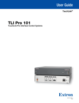
Figure 4. Connecting to a Power Injector
Connecting the Power injector
These touchpanels are powered by a power injector, which must be purchased
separately. Figure 4 shows the Extron XTP PI 100. Your power injector may
look different.
Connect a straight-through Ethernet cable from the power injector to a switch
or router (see gure 4,
1
). This cable carries network information from the
switch or router to the power supply input. A second straight-through cable
(
2
) carries the network information and 48VDC from the power injector to the
touchpanel LAN/PoE connector (see gure 3,
F
, on page 3). Connect the IEC
power cord to a convenient 100 VAC to 240 VAC, 50-60 Hz power source (
3
).
Alternatively, use an Ethernet cable to connect the XTP/LAN/PoE+ port of the
interface to a PoE+ switch
Reset Modes: a Brief Summary
The TLP Pro 525T, 725T, and 1025T Series touchpanels offer the following reset modes (see the TLP Pro 525, 725, and 1025
Series User Guide for complete information):
• Use Factory Firmware — Use this mode with Toolbelt software to replace rmware in the event of conicts arising from
uploading a rmware update.
With the unit powered off, press and hold the Reset button (see gure 3,
C
) while reapplying power to the unit.
• Reset All IP Settings — Use this mode to reset all network settings without affecting user-loaded les.
Press and hold the Reset button for 6 seconds. After the Reset LED (
E
) ashes twice, release and momentarily press the
Reset button.
• Reset to Factory Defaults — Use this mode to return the touchpanel to factory default settings.
Press and hold the Reset button for 9 seconds. After the Reset LED ashes three times, release and momentarily press the
Reset button.
NOTES:
• The factory congured passwords for all accounts on this device have been set to the device serial number.
Passwords can be changed during conguration. Passwords are case sensitive.
• If the device is reset to default settings, the password is the default password conguration. The default password
is extron (for either admin or user accounts).
• Enable or Disable DHCP Client — Use this mode to toggle between DHCP enabled and DHCP disabled. Press the Reset
button ve times, consecutively. After the fth press, do not press the button again within 3 seconds. If DHCP was enabled, it
is now disabled and the Reset LED blinks three times. If DHCP was disabled, it is now enabled and the Reset LED blinks six
times.
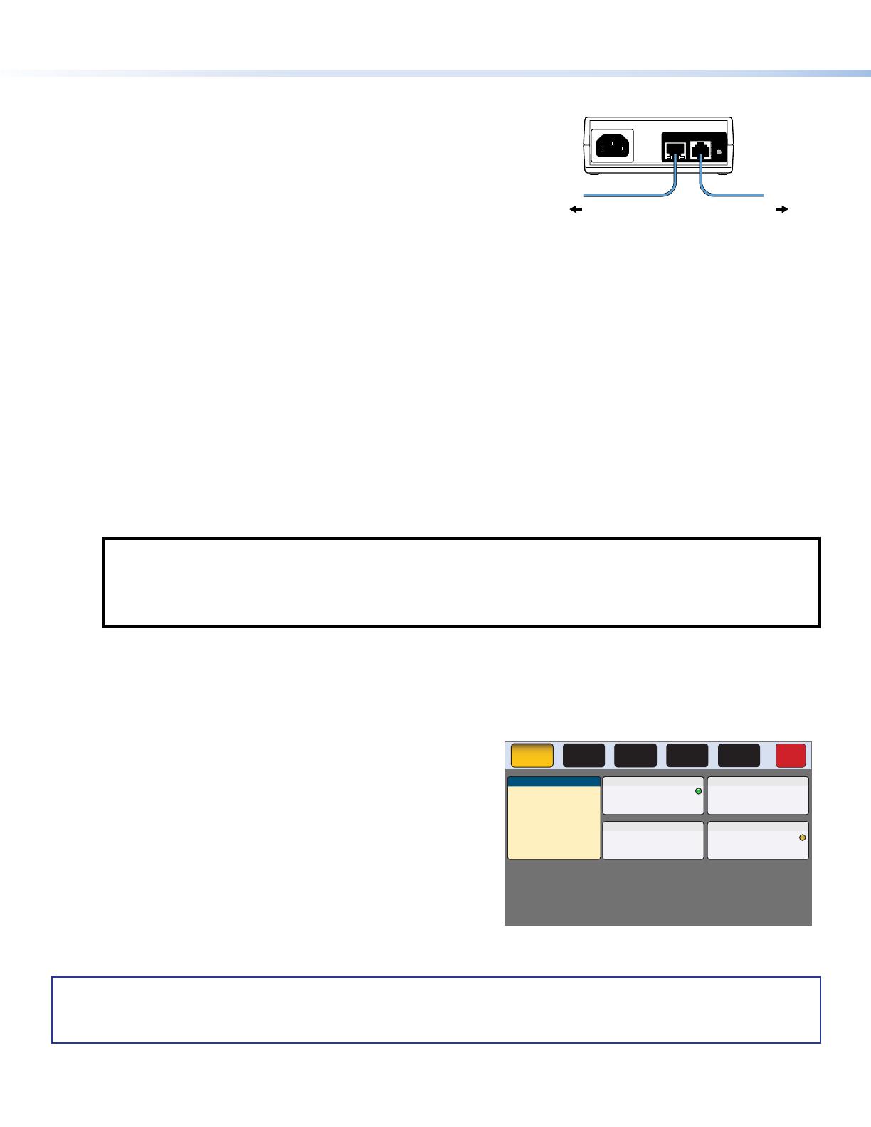
Setup Menu
Figure 5 shows the Setup menu Status screen for the
TLP Pro 725T model. The menu screens for all other models are very
similar.
Press the Menu button (
B
) to open the Setup menu. Select any of
the ve available screens (Status, Network, Display, Audio, and
Advanced) by pressing the appropriate button in the navigation bar
at the top of the screen (for more information, see the TLP Pro 525,
725, and 1025 Series User Guide).
Info
Model: TLP Pro 725T
Part Number:60-1562-02
Firmware
Version:
1.02.0000.b003
PoE: Active
Network
IP Address:
DHCP:
Host Name:
Off
192.168.254.251
TLI-AB-CD-EF
Display
Resolution:
Project:
Sleep Timer:
1024x600
1024x600
5 Minutes
Audio
Master Volume:
Master Mute: Off
100
Status
Display
Audio
Advanced
Exit
Network
Advanced
Controller IP: 192.168.254.250
Project Size: 1/197 MB
Bootloader
Version:
1.03.0000
Figure 5. Setup Menu: Status Screen for TLP Pro 725T
4
68-2831-54 Rev. B
09 20
For information on safety guidelines, regulatory compliances, EMI/EMF compatibility, accessibility, and related topics, see the
Extron Safety and Regulatory Compliance Guide on the Extron website.
For information about replacing and disposing of batteries, see the TLP Pro 525, 725, and 1025 Series User Guide at
www.extron.com.
© 2020 Extron — All rights reserved. www.extron.com
All trademarks mentioned are the property of their respective owners.
Worldwide Headquarters: Extron USA West, 1025 E. Ball Road, Anaheim, CA 92805, 800.633.9876