
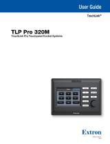
TLP Pro 300M
User Guide
TouchLink
®
TouchLink Pro Touchpanel Control Systems
68-3146-01 Rev. A
04 20

Safety Instructions • English
WARNING: This symbol, , when used on the product, is intended to
alert the user of the presence of uninsulated dangerous voltage within the
product’s enclosure that may present a risk of electric shock.
ATTENTION: This symbol, , when used on the product, is intended
to alert the user of important operating and maintenance (servicing)
instructions in the literature provided with the equipment.
For information on safety guidelines, regulatory compliances, EMI/EMF
compatibility, accessibility, and related topics, see the Extron Safety and
Regulatory Compliance Guide, part number 68-290-01, on the Extron
website,
www.extron.com.
Sicherheitsanweisungen • Deutsch
WARNUNG: Dieses Symbol auf dem Produkt soll den Benutzer darauf
aufmerksam machen, dass im Inneren des Gehäuses dieses Produktes
gefährliche Spannungen herrschen, die nicht isoliert sind und die einen
elektrischen Schlag verursachen können.
VORSICHT: Dieses Symbol auf dem Produkt soll dem Benutzer in
der im Lieferumfang enthaltenen Dokumentation besonders wichtige
Hinweise zur Bedienung und Wartung (Instandhaltung) geben.
Weitere Informationen über die Sicherheitsrichtlinien, Produkthandhabung,
EMI/EMF-Kompatibilität, Zugänglichkeit und verwandte Themen finden Sie
in den Extron-Richtlinien für Sicherheit und Handhabung (Artikelnummer
68-290-01) auf der Extron-Website, www.extron.com.
Instrucciones de seguridad • Español
ADVERTENCIA: Este símbolo, , cuando se utiliza en el producto,
avisa al usuario de la presencia de voltaje peligroso sin aislar dentro del
producto, lo que puede representar un riesgo de descarga eléctrica.
ATENCIÓN: Este símbolo, , cuando se utiliza en el producto, avisa
al usuario de la presencia de importantes instrucciones de uso y
mantenimiento recogidas en la documentación proporcionada con el
equipo.
Para obtener información sobre directrices de seguridad, cumplimiento
de normativas, compatibilidad electromagnética, accesibilidad y
temas relacionados, consulte la Guía de cumplimiento de normativas
y seguridad de Extron, referencia 68-290-01, en el sitio Web de Extron,
www.extron.com.
Instructions de sécurité • Français
AVERTISSEMENT : Ce pictogramme, , lorsqu’il est utilisé sur le
produit, signale à l’utilisateur la présence à l’intérieur du boîtier du
produit d’une tension électrique dangereuse susceptible de provoquer
un choc électrique.
ATTENTION : Ce pictogramme, , lorsqu’il est utilisé sur le produit,
signale à l’utilisateur des instructions d’utilisation ou de maintenance
importantes qui se trouvent dans la documentation fournie avec le
matériel.
Pour en savoir plus sur les règles de sécurité, la conformité à la
réglementation, la compatibilité EMI/EMF, l’accessibilité, et autres sujets
connexes, lisez les informations de sécurité et de conformité Extron, réf.
68-290-01, sur le site Extron, www.extron.com.
Istruzioni di sicurezza • Italiano
AVVERTENZA: Il simbolo, , se usato sul prodotto, serve ad
avvertire l’utente della presenza di tensione non isolata pericolosa
all’interno del contenitore del prodotto che può costituire un rischio di
scosse elettriche.
ATTENTZIONE: Il simbolo, , se usato sul prodotto, serve ad avvertire
l’utente della presenza di importanti istruzioni di funzionamento e
manutenzione nella documentazione fornita con l’apparecchio.
Per informazioni su parametri di sicurezza, conformità alle normative,
compatibilità EMI/EMF, accessibilità e argomenti simili, fare riferimento
alla Guida alla conformità normativa e di sicurezza di Extron, cod. articolo
68-290-01, sul sito web di Extron,
www.extron.com.
Instrukcje bezpieczeństwa • Polska
OSTRZEŻENIE: Ten symbol, , gdy używany na produkt, ma na celu
poinformować użytkownika o obecności izolowanego i niebezpiecznego
napięcia wewnątrz obudowy produktu, który może stanowić zagrożenie
porażenia prądem elektrycznym.
UWAGI: Ten symbol, , gdy używany na produkt, jest przeznaczony do
ostrzegania użytkownika ważne operacyjne oraz instrukcje konserwacji
(obsługi) w literaturze, wyposażone w sprzęt.
Informacji na temat wytycznych w sprawie bezpieczeństwa, regulacji wzajemnej
zgodności, zgodność EMI/EMF, dostępności i Tematy pokrewne, zobacz Extron
bezpieczeństwa i regulacyjnego zgodności przewodnik, część numer 68-290-01,
na stronie internetowej Extron,
www.extron.com.
Инструкция по технике безопасности • Русский
ПРЕДУПРЕЖДЕНИЕ: Данный символ, , если указан
на продукте, предупреждает пользователя о наличии
неизолированного опасного напряжения внутри корпуса
продукта, которое может привести к поражению
электрическим током.
ВНИМАНИЕ: Данный символ, , если указан на продукте,
предупреждает пользователя о наличии важных инструкций
по эксплуатации и обслуживанию в руководстве,
прилагаемом к данному оборудованию.
Для получения информации о правилах техники безопасности,
соблюдении нормативных требований, электромагнитной
совместимости (ЭМП/ЭДС), возможности доступа и других вопросах
см. руководство по безопасности и соблюдению нормативных
требований Extron на сайте Extron: ,
www.extron.com, номер по каталогу - 68-290-01.
安全说明 • 简体中文
警告: 产品上的这个标志意在警告用户该产品机壳内有暴露的危险 电压,
有触电危险。
注意: 产品上的这个标志意在提示用户设备随附的用户手册中有
重要的操作和维护(维修)说明。
关于我们产品的安全指南、遵循的规范、EMI/EMF 的兼容性、无障碍
使用的特性等相关内容,敬请访问 Extron 网站 , www.extron.com,参见 Extron
安全规范指南,产品编号 68-290-01
。
Safety Instructions

安全記事 • 繁體中文
警告: 若產品上使用此符號,是為了提醒使用者,產品機殼內存在著
可能會導致觸電之風險的未絕緣危險電壓。
注意 若產品上使用此符號,是為了提醒使用者,設備隨附的用戶手冊中有
重 要 的 操 作 和 維 護( 維 修 )説 明 。
有關安全性指導方針、法規遵守、EMI/EMF 相容性、存取範圍和相關主題的詳細資
訊,請瀏覽 Extron 網站:www.extron.com,然後參閱《Extron 安全性與法規
遵守手冊》,準則編號 68-290-01。
安全上のご注意
• 日本語
警告: この記号 が製品上に表示されている場合は、筐体内に絶縁されて
いない高電圧が流れ、感電の危険があることを示しています。
注意:この記号 が製品上に表示されている場合は、本機の取扱説明書に
記載されている重要な操作と保守(整備)の指示についてユーザーの注意
を喚起するものです。
安全上のご注意、法規厳守、EMI/EMF適合性、その他の関連項目に
つ い て は 、エ ク スト ロ ン の ウェブ サ イト www.extron.com よ り 『 Extron Safety
and Regulatory Compliance Guide』 ( P/N 68-290-01) をご覧ください。
안전 지침 • 한국어
경고: 이 기호 가 제품에 사용될 경우, 제품의 인클로저 내에 있는
접지되지 않은 위험한 전류로 인해 사용자가 감전될 위험이 있음을
경고합니다.
주의: 이 기호 가 제품에 사용될 경우, 장비와 함께 제공된 책자에 나와
있는 주요 운영 및 유지보수(정비) 지침을 경고합
니다.
안전 가이드라인, 규제 준수, EMI/EMF 호환성, 접근성, 그리고 관련 항목에
대한 자세한 내용은 Extron 웹 사이트(www.extron.com)의 Extron 안전 및
규제 준수 안내서, 68-290-01 조항을 참조하십시오.
Copyright
© 2020 Extron Electronics. All rights reserved.
Trademarks
All trademarks mentioned in this guide are the properties of their respective owners.
The following registered trademarks(
®
), registered service marks(
SM
), and trademarks(
TM
) are the property of RGBSystems, Inc. or
Extron Electronics (see the current list of trademarks on the Terms of Use page at www.extron.com):
Registered Trademarks
(
®
)
Cable Cubby, ControlScript, CrossPoint, DTP, eBUS, EDID Manager, EDID Minder, Extron, Flat Field, FlexOS, Glitch Free, Global Configurator,
Global Scripter, GlobalViewer, Hideaway, HyperLane, IPIntercom, IPLink, Key Minder, LinkLicense, LockIt, MediaLink, MediaPort, NAV,
NetPA, PlenumVault, PoleVault, PowerCage, PURE3, Quantum, ShareLink, Show Me, SoundField, SpeedMount, SpeedSwitch, StudioStation,
System INTEGRATOR, TeamWork, TouchLink, V-Lock, VideoLounge, VN-Matrix, VoiceLift, WallVault, WindoWall, XPA, XTP, XTP Systems, and
ZipClip
Registered Service Mark
(SM)
: S3 Service Support Solutions
Trademarks
(
™
)
AAP, AFL (Accu-Rate Frame Lock), ADSP (Advanced Digital Sync Processing), Auto-Image, AVEdge, CableCover, CDRS (Class D
Ripple Suppression), Codec Connect, DDSP (Digital Display Sync Processing), DMI (Dynamic Motion Interpolation), DriverConfigurator,
DSPConfigurator, DSVP (Digital Sync Validation Processing), eLink, EQIP, Everlast, FastBite, Flex55, FOX, FOXBOX, IP Intercom HelpDesk,
MAAP, MicroDigital, Opti-Torque, PendantConnect, ProDSP, QS-FPC (QuickSwitch Front Panel Controller), Room Agent, Scope-Trigger, SIS,
Simple Instruction Set, Skew-Free, SpeedNav, Triple-Action Switching, True4K, True8K, Vector™ 4K, WebShare, XTRA, and ZipCaddy

FCC Class A Notice
This equipment has been tested and found to comply with the limits for a Class A digital
device, pursuant to part15 of the FCC rules. The ClassA limits provide reasonable protection
against harmful interference when the equipment is operated in a commercial environment.
This equipment generates, uses, and can radiate radio frequency energy and, if not installed
and used in accordance with the instruction manual, may cause harmful interference to radio
communications. Operation of this equipment in a residential area is likely to cause interference.
This interference must be corrected at the expense of the user.
NOTES:
• This unit was tested with shielded I/O cables on the peripheral devices. Shielded cables
must be used to ensure compliance with FCC emissions limits.
• For more information on safety guidelines, regulatory compliances, EMI/EMF
compatibility, accessibility, and related topics, see the Extron Safety and Regulatory
Compliance Guide on the Extron Website.
Battery Notice
This product contains a battery. Do not open the unit to replace the battery. If the
battery needs replacing, return the entire unit to Extron (for the correct address, see the Extron
Warranty section on the last page of this guide).
CAUTION: Risk of explosion if battery is replaced by an incorrect type. Dispose of used
batteries according to the instructions.
ATTENTION : Risque d’explosion. Ne pas remplacer la pile par le mauvais type de pile.
Débarrassez-vous des piles utilisées selon le mode d’emploi.

Conventions Used in this Guide
Notifications
In this user guide, the following are used:
WARNING: Potential risk of severe injury or death.
AVERTISSEMENT : Risque potentiel de blessure grave ou de mort.
CAUTION: Risk of minor personal injury.
ATTENTION : Risque de blessuremineure.
ATTENTION:
• Risk of property damage.
• Risque de dommages matériels.
NOTE: A note draws attention to important information.
Software Commands
NOTE: For commands and examples of computer or device responses mentioned in
this guide, the character “
0” is used for the number zero and “O” represents the capital
letter “
o”.
Directory paths that do not have variables are written in the font shown here:
C:\Program Files\Extron
Variables are written in slanted form as shown here:
ping xxx.xxx.xxx.xxx —t
SOH R Data STX Command ETB ETX
Selectable items, such as menu names, menu options, buttons, tabs, and field names are
written in the font shown here:
From the File menu, select New.
Click the OK button.
Specifications Availability
Product specifications are available on the Extron Website, www.extron.com.
Extron Glossary of Terms
A glossary of terms is available at www.extron.com/technology/glossary.aspx.


Contents
Introduction............................................................ 1
About the TLP Pro 300M .................................... 1
Features ............................................................. 1
Application Diagram ........................................... 2
Requirements ..................................................... 2
Software ......................................................... 2
Hardware ........................................................ 2
Installation Overview ........................................... 3
Panel Features ...................................................... 5
TLP Pro 300M Front Panel Features ................... 5
TLP Pro 300M Rear Panel Features .................... 6
Connecting a Power Injector ........................... 7
Setup Menu ............................................................ 9
Status ............................................................... 10
Network ........................................................... 11
Display ............................................................. 14
Audio ................................................................ 15
Project Information ........................................... 16
Advanced ......................................................... 17
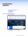
Configuration Software ..................................... 19
Downloading and Installing Software ................ 19
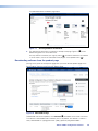
Downloading software from
the product page ......................................... 20
Downloading software from
the alphabet menu ....................................... 21
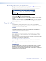
Using the Software ........................................... 21
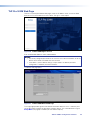
TLP Pro 300M Web Page ................................. 22
Updating Firmware ........................................... 23
Downloading Firmware ................................. 23
Updating Firmware Using the
Touchpanel Web Page ................................. 24
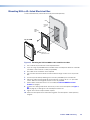
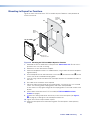
Mounting ............................................................... 25
Mounting With a UL-listed Electrical Box .......... 26
Mounting to Drywall or Furniture ....................... 27
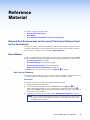
Reference Material ............................................. 28
Network Port Requirements and Licensed
Third-party Software Used
by the Touchpanels ......................................... 28
Reset Modes .................................................... 28
Use Factory Firmware ................................... 28
Reset All IP Settings ..................................... 29
Reset to Factory Defaults .............................. 29
Enable or Disable the DHCP Client ............... 30
Secure Sockets Layer (SSL) Certificates ........... 30
IEEE 802.1X Certificates ................................... 31
Certificate File Requirements......................... 31
Private Key File Requirements ....................... 31
TLP Pro 300M • Contents vii

TLP Pro 300M • Contents viii

Introduction
This guide describes the function, installation, and operation of the TLPPro300M
TouchLinkPro touchpanel. Unless otherwise stated, the terms “TLP Pro” and “touchpanel”
refer to the TLP Pro 300M.
This section contains the following information:
• About the TLP Pro 300M
• Features
• Application Diagram
• Requirements
About the TLP Pro 300M
The Extron TLP Pro 300M is a 3.5-inch, wall-mounted touchpanel with an 320x480 LCD
touchscreen. The TLP Pro 300M works with any Extron IP Link Pro control processor and is
ideal for any AV application requiring a compact touchpanel and a fully customizable interface.
The touchpanel mounts in a portrait orientation to a standard 1-gang electrical box (see
Mounting on page 25).
Power over Ethernet (PoE) allows the touchpanel to receive power and communications over a
single Ethernet cable.
The screen layout is designed with the Extron GUI Designer software. The functions are
assigned to the screen objects with the Extron Global Configurator Plus and Professional
software or Global Scripter. The user can define the graphics and the functions associated with
those graphics, providing versatility and adaptability to the configuration and control of an AV
system.
A motion sensor, light sensor, and a speaker provide sleep mode, auto dimming, and audible
feedback.
Features
3.5-inch LCD touchscreen — with 320x480 resolution and 18-bit color depth.
Gorilla Glass
®
screen is tough, scratch, and smudge-resistant — Corning
®
Gorilla Glass
is stronger and more scratch-resistant than standard glass, while maintaining touch sensitivity,
color saturation, and brightness.
Compatible with all Extron IP Link Pro control processors and HC 400 Series
systems.
Power over Ethernet (PoE 802.3af, class2) compliance — allows the touchpanel to
receive power and control over a single Ethernet cable, eliminating the need for a local power
supply. The power injector is sold separately.
Built-in speaker — provides audible feedback from button presses.
Light sensor — adjusts screen brightness as the ambient room lighting changes.
Configurable red and green status lights — indicate the availability or call status of a room.
Automatic clock synchronization — allows touchpanel to display the accurate time and
date.
Energy-saving features —
• Adjustable sleep timer puts touchpanel into sleep mode.
• Motion detector wakes touchpanel.
TLP Pro 300M • Introduction 1

Fully customizable using Extron control system software — using GUI Designer,
Global Configurator Plus and Professional, and Toolbelt.
Multiple mounting options — mounts in a one-gang junction box, on a wall, or in a
lectern.
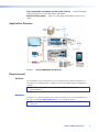
Application Diagram
Figure 1. TLP Pro 300M Application Diagram
Requirements
Software
For a complete list of the requirements for running GUI Designer, Global Configurator Plus
and Professional, Global Scripter, or Toolbelt, see the Extron Web page for the appropriate
software.
NOTE: The TLP Pro 300M is not compatible with GlobalConfigurator 3 or
GUIConfigurator.
Hardware
An Extron IP Link Pro control processor must be connected to the same network domain as
the TLP Pro 300M. See www.extron.com for a list of suitable controllers.
NOTE: The TLP Pro 300M is not compatible with Extron IP Link (non-Pro) control
processors.
TLP Pro 300M • Introduction 2

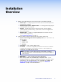
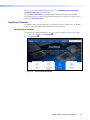
Installation
Overview
1. Before starting, download and install the latest versions of the following software:
GUI Designer — for designing layouts for Extron TouchLink Pro touchpanels and
third party touch interfaces.
Global Configurator Plus and Professional — for setting up and configuring the
control processor and touchpanel.
Toolbelt — provides device discovery, device information, firmware updates,
and configuration of network settings, system utilities, and user management for
TouchLink Pro devices.
Global Scripter — Provides an integrated development environment for Extron
control systems programming.
See Configuration Software on page 19.
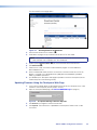
2. Obtain the following network information from your network administrator:
Dynamic Host Configuration Protocol (DHCP) status (on or off). If DHCP is off,
you also require
IP address
Subnet mask
Gateway
User names— These are either admin or user.
Passwords — The factory configured passwords for all accounts on this device
have been set to the device serial number. Passwords can be changed during
configuration. Passwords are case sensitive.
NOTE: If the device is reset to default settings, the password is the default
password configuration. The default password is extron (for either admin or
user accounts).
MAC address — make a note of the touchpanel MAC address.
SSL security certificates and IEEE 802.1X authentication — Extron
touchpanels come with a factory-installed Secure Sockets Layer (SSL) security
certificate. IEEE 802.1X authentication is also supported once enabled. See
Secure Sockets Layer (SSL) Certificates on page 30 or IEEE 802.1X
Certificates
on page 31 for more information.
TLP Pro 300M • Installation Overview 3

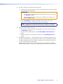
3. Set up the Touchpanels for Network Communication:
Connect the PC that you will use for setup, the control processor, and the touchpanel
to the same Ethernet subnetwork.
ATTENTION:
• Do not power on the touchpanels or control processors until you have read
the Attention on page 8.
• Ne branchez pas les écrans tactiles ou les contrôleurs avant d’avoir lu les
mises en garde page 8.
Use the Setup Menu (see page 9) or Toolbelt to set the DHCP status and, if
necessary, the IP address and related settings for the touchpanel.
NOTE: Set up the touchpanel before mounting. Once the panel is mounted in a
wall, the Menu button cannot be accessed without removing the touchpanel.
4. Mount and connect cables to the units:
Mount the units. There are several mounting options for Touchlink Pro touchpanels
(see Mounting on page 25).
Connect cables to the touchpanels (see TLP Pro 300M Rear Panel Features on
page 6).
Connect the power cords and power on all devices (see LAN/PoE Connector on
page 6).
5. Configure the Touchpanels — the GUI Designer Help File, the Global Configurator Help
File, and the Toolbelt Help File, provide step-by-step instructions and detailed information.
The Global Configurator Help File includes an introduction to that software and sections
on how to start a project and configuration.
Global Scripter provides an Extron-exclusive Python library (ControlScript) and Global
Scripter modules to get you started. See the GlobalScripter Help File for more information.
TLP Pro 300M • Installation Overview 4

Panel Features
This section describes:
• TLP Pro 300M Front Panel Features
• TLP Pro 300M Rear Panel Features
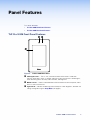
TLP Pro 300M Front Panel Features
A
A
A
B
B
BC
C
C
Figure 2. TLP Pro 300M Front Panel
A
LCD touchscreen — The 3.5-inch, 320x480 resolution touchscreen is made with
Corning
®
Gorilla Glass, which is stronger and more scratch-resistant than standard glass,
while maintaining touch sensitivity, color saturation, and brightness.
B
Motion sensor — Detects motion between three to five feet from the touchpanel, and at
least 15° from the center axis.
C
Light sensor — Monitors ambient light level and adjusts screen brightness, based on the
settings configured using the Setup Menu (see page 9).
TLP Pro 300M • Panel Features 5

TLP Pro 300M Rear Panel Features
B
B
B
C
C
C
D
D
D
A
A
A
G
G
G
H
H
H
E
E
E
F
F
F
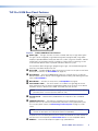
Figure 3. TLP Pro 300M Rear Panel Features
A
Status light — The lights can blink or remain lit steadily and they can light red or green.
The lights can be configured (using Global Configurator) or programmed (using Global
Scripter) to provide feedback information about the system using these variables. Different
combinations, for example a red LED lit steadily or a green LED that is blinking, can be
associated with different events to provide indications about the system.
For information about configuring or programming this light, see the Global Configurator
Help File or the Global Scripter Help File.
B
Reset LED — Provides feedback about the reset status when the user presses the Reset
button (for an overview, see Reset Modes on page 28).
C
Reset Button — Pressing the Reset button allows the unit to be reset in any of three
different modes and can also be used to toggle between enabling and disabling the DHCP
client (see Reset Modes).
D
Menu Button — Activates the setup menu (see Setup Menu on page 9).
E
Serial Number Label — The serial number is on a label on the right edge of the rear
panel, towards the top. The factory configured passwords for all accounts on this device
have been set to this device serial number. Passwords are case sensitive.
NOTE: If the device is reset to default settings, the passwords are reset to the default
password, which is extron (for either admin or user).
F
Security Screw — Used to attach provided tether kit. It requires a Torx screwdriver
(size T8).
G
LAN/PoE Connector — The interface is compliant with the requirements of PoE
(PoE 802.3af, class 2) and must be powered by PoE power sourcing equipment (PSE).
This can be a power injector (see Connecting a Power Injector on page 7) or PoE
switch.
NOTE: The PoE PSE must be purchased separately. Use an Ethernet cable to
connect the touchpanel to a PoE power injector (not provided).
An Extron IP Link Pro control processor must also be connected to the same network as
the TouchLink Pro touchpanel (see www.extron.com for a list of compatible models).
H
USB Port — One micro-B receptacle supports high-speed USB 2.0.
figure 3
LAN/PoE Connector
TLP Pro 300M • Panel Features 6

Connecting a Power Injector
Figure 4 shows the Extron XTP PI 100. Your power injector may look different.
1. Connect a straight-through Ethernet cable from the power injector to a switch or router
(figure 4,
1
). This cable carries network information from the switch or router to the
power supply.
100-240V
~
50-60Hz
0.4A MAX
XTP
PWR
XTP PWR
To network switchTo touchpanel
1
1
12
2
2
3
3
3
Figure 4. XTP PI 100 Power Injector
2. Connect a second straight-through cable (
2
) from the power injector to the touchpanel.
This cable carries the network information and 48VDC from the power injector to the
touchpanel.
3. Connect the IEC power cord to a convenient 100 VAC to 240 VAC, 50-60 Hz power
source (
3
).
TLP Pro 300M • Panel Features 7

ATTENTION:
•
The TLP Pro 300M is intended for connection to a Power over Ethernet circuit for
intra-building use only and are considered to be part of a Network Environment 0 per
IEC TR62101.
• Le TLP Pro 300M est conçu pour une connexion à un circuit PoE pour une utilisation
intérieure seulement et est considéré comme faisant partie d’un environnement réseau
0 par IECTR62101.
• Always use a power supply provided by or specified by Extron. Use of an
unauthorized power supply voids all regulatory compliance certification and may
cause damage to the supply and the end product.
• Utilisez toujours une source d’alimentation fournie ou recommandée par Extron.
L’utilisation d’une source d’alimentation non autorisée annule toute conformité
réglementaire et peut endommager la source d’alimentation ainsi que le produit final.
• This product is intended for use with a UL Listed power source marked “Class 2” or
“LPS” and rated 48 VDC (PoE), minimum 0.35 A.
• Ce produit est destiné à une utilisation avec une source d’alimentation listéeUL avec
l’appellation «Classe2» ou «LPS» et normée 48Vcc (PoE), 0,35A minimum.
• Extron power supplies are certified to UL/CSA 60950-1 and are classified as LPS
(Limited Power Source). Use of a non-LPS or unlisted power supply will void all
regulatory compliance certification.
• Les sources d’alimentation Extron sont qualifiées UL/CSA60950-1 et sont
classéesLPS(LimitedPowerSource). L’utilisation d’une source d’alimentation non-
listée ou non-listéeLPS annulera toute certification de conformité réglementaire.
• Unless otherwise stated, the AC/DC adapters are not suitable for use in air handling
spaces or in wall cavities. The power supply is to be located within the same vicinity
as the Extron AV processing equipment in an ordinary location, Pollution Degree 2,
secured to the equipment rack within the dedicated closet, podium, or desk.
• Sauf mention contraire, les adaptateurs AC/DC ne sont pas appropriés pour une
utilisation dans les espaces d’aération ou dans les cavités murales. La source
d’alimentation doit être située à proximité de l’équipement de traitement audiovisuel
dans un endroit ordinaire, avec un degré2 de pollution, fixé à un équipement de rack
à l’intérieur d’un placard, d’une estrade, ou d’un bureau.
• Power over Ethernet (PoE) is intended for indoor use only. It is to be connected only to
networks or circuits that are not routed to the outside plant or building.
• L’alimentation via Ethernet (PoE) est destinée à une utilisation en intérieur uniquement.
Elle doit être connectée seulement à des réseaux ou des circuits qui ne sont pas
routés au réseau ou au bâtiment extérieur.
• The installation must always be in accordance with the applicable provisions of
National Electrical Code ANSI/NFPA 70, article 725 and the Canadian Electrical Code
part 1, section 16.
• Cette installation doit toujours être en accord avec les mesures qui s’applique au
National Electrical Code ANSI/NFPA70, article725, et au Canadian Electrical Code,
partie1, section16.
• The power supply shall not be permanently fixed to building structure or similar
structure.
• La source d’alimentation ne devra pas être fixée de façon permanente à une structure
de bâtiment ou à une structure similaire.
Attention
mises en garde
TLP Pro 300M • Panel Features 8

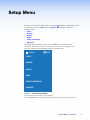
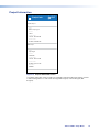
Setup Menu
When the TLP Pro 300M is powered on, the currently loaded project is displayed. To access
the setup menu, press the Menu button (see figure 3,
D
, on page 6). There are six
available screens:
• Status
• Network
• Display
• Audio
• Project Information
• Advanced
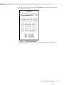
To navigate between different screens, press the Menu icon in the top left corner.
The screen selection menu opens over the current screen, which is grayed out. The
menu has five buttons, corresponding to the five available screens:
Status EXIT
STATUS
NETWORK
DISPLAY
AUDIO
PROJECT INFORMATION
ADVANCED
Figure 5. Screen Selection Menu
Press the name of the screen you wish to open.
Press the Exit button in the top right corner of the screen to close the menu screens.
TLP Pro 300M • Setup Menu 9

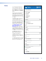
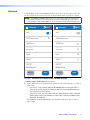
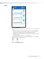
Status
This screen opens by default. To
access the Status screen from
any other part of the Setup menu,
press the Menu icon in the top left
corner and then press the Status
button.
Figure 6 shows the entire Status
screen. Because of size of the
touchscreen, you can only see part
of the Status screen at any time.
Scroll up or down within the screen
to navigate.
The Status screen is a read-only
screen that provides basic
information about the touchpanel.
Each section of the screen shows a
summary of the information on the
other screens. More information
about each topic can be found on
the Network, Display, Audio,
Project Information, and
Advanced screens. To navigate
to the appropriate screen, click the
arrow (>) next to the appropriate
heading. Alternatively, you can use
the Menu icon in the top left corner.
In the Network section, a
green circle with a white check
mark is shown next to the
IP address, when there is a
network connection. If there is no
connection, the circle is red with a
white cross.
In the Advanced section, the same
icons are used to show if a control
processor is connected or not.
Status EXIT
Device Information
60-1667-02
Model
TLP Pro 300M
Part Number
1.00.0000-b010
Firmware
1.00.0002
Bootloader
Network
TLP-Pro-300M-AB-CD-EF
IP Address
192.168.254.251
Hostname
Off
DHCP
Display
119
Resolution
320x480
Sleep Timer
Audio
Off
Master Volume
80
Master Mute
Project Information
System Project Name
GUI Project Name
Advanced
Primary Controller Address
192.168.254.250
System ID
1 / 4313 MB
6661
Storage
N/A
N/A
Figure 6. Status Screen
TLP Pro 300M • Setup Menu 10

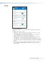
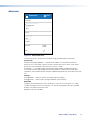
Network
The image below shows the entire Network screen. Because of size of the touchscreen, you
can only see part of the screen at any time. Scroll up or down within the screen to navigate.
NOTE: The Cancel and Save buttons float so that they always appear at the bottom of
the screen, even when only the top part of the screen is displayed. They are used to
save changes to the network addresses or to cancel the changes without saving them.
NetworkEXIT
Save
DHCP
TLP-Pro-300M-AB-CD-EF
Hostname
192.168.254.251
IP Address
255.255.255.0
Subnet Mask
0.0.0.0
Gateway
127.0.0.1
DNS Primary
00-05-A6-AB-CD-EF
MAC Address
Domain Name
extron.com
Cancel
Networ
kE
XIT
DHCP
TLP-Pro-300M-AB-CD-EF
Hostname
192.168.254.251
IP Address
255.255.255.0
Subnet Mask
0.0.0.0
Gateway
127.0.0.1
DNS Primary
00-05-A6-AB-CD-EF
MAC Address
Domain Name
extron.com
Save
Cancel
Figure 7.
Network Screen: DHCP on (left) and DHCP off (right)
The Domain Name and MAC Address are read-only.
1. If the IP addresses are assigned by DHCP, move the DHCP slider to the right, as shown in
figure 7 (left).
• When DHCP is on, the Host Name can be edited by pressing the right arrow (>).
There are no arrows next to the addresses and they cannot be edited because
they are set by the DHCP server.
• When DHCP is off, the arrow next to the Host Name disappears and it cannot be
edited. Arrows next to the IP Address, Subnet Mask, Gateway and DNS Primary
allow them to be edited.
If IP addresses are assigned manually, move the DHCP slider to the left, as shown in
figure 7 (right).
TLP Pro 300M • Setup Menu 11

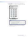
2. If DHCP is on, press the arrow next to the Host Name button to edit the host name. The
Host Name dialog box opens:
Hostname
TLP-Pro-300M-AB-CD-EF
X
qwertyuiop
asdfgh jkl
zxcvbnm-
123 SUBMIT
x
Figure 8. Host Name Dialog Box
Use the keypad to enter a new name, which appears in the Host Name text box.
TLP Pro 300M • Setup Menu 12
Page is loading ...
Page is loading ...
Page is loading ...
Page is loading ...
Page is loading ...
Page is loading ...
Page is loading ...
Page is loading ...
Page is loading ...
Page is loading ...
Page is loading ...
Page is loading ...
Page is loading ...
Page is loading ...
Page is loading ...
Page is loading ...
Page is loading ...
Page is loading ...
Page is loading ...
Page is loading ...
-
 1
1
-
 2
2
-
 3
3
-
 4
4
-
 5
5
-
 6
6
-
 7
7
-
 8
8
-
 9
9
-
 10
10
-
 11
11
-
 12
12
-
 13
13
-
 14
14
-
 15
15
-
 16
16
-
 17
17
-
 18
18
-
 19
19
-
 20
20
-
 21
21
-
 22
22
-
 23
23
-
 24
24
-
 25
25
-
 26
26
-
 27
27
-
 28
28
-
 29
29
-
 30
30
-
 31
31
-
 32
32
-
 33
33
-
 34
34
-
 35
35
-
 36
36
-
 37
37
-
 38
38
-
 39
39
-
 40
40


Extron electronics TouchLink TLP Pro 520M User manual
- Type
- User manual
- This manual is also suitable for
Ask a question and I''ll find the answer in the document
Finding information in a document is now easier with AI
in other languages
Related papers
-
Extron electronics TLP Pro 300M Series User manual
-
Extron electronics TouchLink TLP Pro 525C Series User manual
-
 Extron electronics TouchLink TLP Pro 520M User manual
-
Extron electronics TLP Pro 1225 Series User manual
-
Extron TLP Pro 1220MG User manual
-
Extron electronics TLP Pro 525T User manual
-
Extron electronics TLP Pro 1220MG User manual
-
Extron electronics TLP Pro 320M User manual
-
-

Other documents
-
Extron TLP Pro 300M Series Touch Panel User guide
-
-
-
Kramer Electronics BC-2S-300M Datasheet
-
-
-
Extron TLP Pro 525T User manual
-
-
-