Page is loading ...


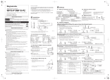
July 2002 HEIDENHAIN iTNC 530 Service Manual

July 2002 HEIDENHAIN Service Manual iTNC 530
1 Using the Service Manual ..................................................................................................... 5
1.1 General ............................................................................................................................ 5
1.2 Safety Precautions........................................................................................................... 6
2 Integral Monitoring System.................................................................................................. 7
2.1 Introduction ..................................................................................................................... 7
2.2 Monitoring Functions....................................................................................................... 8
2.2.1 Position monitoring ................................................................................................ 8
2.2.2 Nominal speed value monitoring ........................................................................... 9
2.2.3 Movement monitoring ........................................................................................... 9
2.2.4 Standstill monitoring ............................................................................................ 10
2.2.5 Positioning window ............................................................................................. 10
2.2.6 Monitoring of the power supply unit ................................................................... 12
2.2.7 Temperature monitoring ...................................................................................... 13
2.2.8 I
2
t monitoring ....................................................................................................... 14
2.2.9 Read actual utilization of drive motors ................................................................. 15
2.2.10 Status of HEIDENHAIN inverters ....................................................................... 15
2.2.11 EMERGENCY STOP monitoring ........................................................................ 15
2.3 Error Messages ............................................................................................................. 17
2.4 Log................................................................................................................................. 85
3 Errors and Error Analysis on the Machine or Control ...................................................... 89
3.1 Overview ....................................................................................................................... 89
4 Reserved ............................................................................................................................... 91
4.1 ....................................................................................................................................... 91
5 Overview of Components ................................................................................................... 93
5.1 Standard Components................................................................................................... 93
5.2 Accessories ................................................................................................................... 96
6 Important Features of HEIDENHAIN Components ........................................................... 97
6.1 Hardware Identification ................................................................................................. 97
6.2 Display of System Information .................................................................................... 100
7 Connector Designation and Layout.................................................................................. 103
7.1 MC and CC .................................................................................................................. 103
7.1.1 Designation and position of connectors ............................................................ 103
7.1.2 Pin layouts ......................................................................................................... 105
7.2 PLC Expansion Boards ................................................................................................ 125
7.2.1 Designation and position of connectors ............................................................ 125
7.2.2 Pin layouts ......................................................................................................... 127
7.3 iTNC Operating Panel ................................................................................................. 133
7.3.1 Designation and position of connectors ............................................................ 133
7.3.2 Pin layouts ......................................................................................................... 133
7.4 Visual Display Units ..................................................................................................... 135
7.4.1 BF 120 .............................................................................................................. 135
7.4.2 BF 150 .............................................................................................................. 138
7.5 Interface Card for Simodrive 611D .............................................................................. 140
7.5.1 Interface card Id.Nr. 324 955-xx ........................................................................ 140
7.5.2 Interface card Id.Nr. 31 437-xx .......................................................................... 141
7.5.3 Interface card Id.Nr. 324 952-1x ........................................................................ 142
7.5.4 Interface card Id.Nr. 324 952-0x ........................................................................ 143
7.6 Machine Operating Panel ........................................................................................... 144
7.6.1 MB 420 .............................................................................................................. 144
7.7 Handwheels................................................................................................................. 146
7.7.1 HR 130 (Panel-mounted handwheel) ................................................................. 146
7.7.2 HR 410 (Portable handwheel) ............................................................................ 147
7.7.3 HRA 110 (Multi-axis handwheel) ....................................................................... 149
Contents

HEIDENHAIN Service Manual iTNC 530
7.8 Touch Probe Systems ................................................................................................. 150
7.8.1 TS 220 ............................................................................................................... 150
7.8.2 TS 632 ............................................................................................................... 151
7.8.3 TT 130 ................................................................................................................ 153
8 Grounding Diagrams and Block Diagrams ...................................................................... 154
8.1 Grounding Diagram ..................................................................................................... 154
8.2 Basic Circuit Diagrams ................................................................................................ 155
8.3 Block diagram.............................................................................................................. 160
9 Power Supply..................................................................................................................... 165
9.1 Power Supply for the iTNC 530................................................................................... 165
9.2 Power Supply for Control-Is-Ready Signal................................................................... 170
9.3 Buffer Battery.............................................................................................................. 171
9.4 Info Menu.................................................................................................................... 172
9.5 Power Supply for PLC Outputs ................................................................................... 173
9.5.1 General .............................................................................................................. 173
9.5.2 Power supply for the PLC outputs of MC 422 .................................................. 173
9.5.3 Supply voltage for PLC outputs on the PL 4xx B ............................................... 174
9.6 Power Supply for the Display Units............................................................................. 176
10 TE 420 and TE 530 Keyboard Units ................................................................................ 177
10.1 Front View of the Keyboard Units ............................................................................. 177
10.1.1 TE 420 ........................................................................................................... 177
10.1.2 TE 530 ............................................................................................................ 178
10.2 Checking the Keyboard Unit...................................................................................... 179
10.3 Key Matrix of the TE 420 Keyboard Unit ................................................................... 181
10.3.1 TE 420 ............................................................................................................. 181
10.3.2 TE 530 ............................................................................................................. 186
10.3.3 Keys on the VDUs ........................................................................................... 196
10.3.4 MB 420 machine operating panel .................................................................... 198
11 Visual Display Units......................................................................................................... 199
11.1 Checking the BC 120F Visual Display Unit ................................................................ 199
11.2 Checking the BC 150 Visual Display Unit .................................................................. 200
12 File Management of iTNC ............................................................................................... 201
12.1 Code Numbers .......................................................................................................... 201
12.2 Where are Which Data in the iTNC? ......................................................................... 201
12.3 TNC Partition (TNC:\) ................................................................................................. 203
12.4 PLC Partition (PLC:\) .................................................................................................. 205
12.5 Machine Parameter Editor......................................................................................... 207
12.6 Switching the Position Display for Service Purposes................................................ 209
13 Encoder Interface ............................................................................................................. 211
13.1 Position Encoders Circuit .......................................................................................... 211
13.2 Speed Encoders Circuit ............................................................................................. 213
13.3 Checking Position and Speed Encoders.................................................................... 215
13.4 Traverse with Indirect Distance Measurement (Emergency Operation)
.......................................................................................................................................... 216
14 Reference Marks .............................................................................................................. 217
14.1 Definition ................................................................................................................... 217
14.2 Traversing the Reference Marks ............................................................................... 217

July 2002 HEIDENHAIN Service Manual iTNC 530
15 Checking the Enables on the iTNC................................................................................. 225
15.1 General ...................................................................................................................... 225
15.2 Examination............................................................................................................... 227
15.2.1 Examination of the control-is-ready output (X41/pin 34) and the control-is-ready si-
gnal acknowledgment
..................................................................................................... input I3 (X42/pin 4). 227
15.2.2 Checking the global drive enable I32, connector X42 / pin 33 ......................... 228
15.2.3 Checking the drive enabling for the axis groups via connector X150 (if wired) 228
15.2.4 Checking the readiness of the inverter system ............................................... 229
15.2.5 Checking PLC modules, markers and words ................................................... 230
16 Interface to Servo Amplifier............................................................................................ 231
16.1 Analog/Digital Nominal Value to Servo Amplifier....................................................... 231
16.2 Overview of Test Routines for Error Diagnosis ......................................................... 232
16.2.1 Test routine 1, Checking the analog speed command interface ..................... 233
16.2.2 Test routine 2 ................................................................................................... 235
16.2.3 Test routine 3 ................................................................................................... 237
16.2.4 Test routine 4 ................................................................................................... 238
16.2.5 Test routine 5 ................................................................................................... 239
16.2.6 Test routine 6 ................................................................................................... 240
16.3 Speed Adjustment at Servo Amplifier ....................................................................... 241
16.4 Adjusting the Electrical Offset................................................................................... 242
17 Integrated Oscilloscope................................................................................................... 245
18 PLC Interface .................................................................................................................... 251
18.1 Specifications ............................................................................................................ 251
18.2 Monitoring the PLC Inputs and Outputs.................................................................... 252
18.3 Service Diagnosis in PLC mode................................................................................. 255
18.3.1 TRACE function ............................................................................................... 255
18.3.2 LOGIC diagram ................................................................................................ 256
18.3.3 TABLE Function ............................................................................................... 258
18.4 Re-Compile the PLC program.................................................................................... 259
18.5 Calling the PLC Error Table (<Name>.PET) for Diagnosis Purposes ......................... 260
18.6 Nonvolatile PLC Markers and Words......................................................................... 261
19 Serial Handwheels ........................................................................................................... 263
19.1 HR 130 Handwheel ................................................................................................... 263
19.2 HR 410 Handwheel ................................................................................................... 264
20 Touch Probe Systems...................................................................................................... 267
20.1 Overview ................................................................................................................... 267
20.1.1 Touch probes for workpiece measurement ..................................................... 267
20.1.2 Touch probe for tool measurement ................................................................. 267
21 Data Interfaces ................................................................................................................. 269
21.1 Cable Overview ......................................................................................................... 269
21.1.1 Ethernet interface RJ45 port ........................................................................... 269
21.1.2 RS-232-C/V.24 .................................................................................................. 269
21.1.3 RS-422/V.11 ..................................................................................................... 270
21.2 Data Interface Operating Modes............................................................................... 271
21.2.1 Overview of operating modes ......................................................................... 271
21.2.2 Interface configuration and assignment of mode ............................................ 272
22 Transfer of Files via Data Interface................................................................................. 273
22.1 The Data Transfer Menu............................................................................................ 273
22.2 Downloading Files from the iTNC via Data Interface................................................. 274
22.3 Uploading Files onto the iTNC via Data Interface ...................................................... 277

HEIDENHAIN Service Manual iTNC 530
23 Replacing Instructions..................................................................................................... 279
23.1 Important Information ............................................................................................... 279
23.2 NC Software Update for PGM no. 340420/421......................................................... 281
23.3 Activating an Existing NC Software in the Control .................................................... 286
23.4 Backup/Restoring Hard-Disk Data ............................................................................. 287
23.4.1 Data backup ..................................................................................................... 287
23.4.2 Extracting files from the backup file ................................................................ 289
23.4.3 Restoring the data ........................................................................................... 290
23.5 Exchanging the MC ................................................................................................... 292
23.6 Exchanging the CC .................................................................................................... 294
23.7 Exchanging the Hard Disk ......................................................................................... 295
24 Inspection, Measuring and Test Equipment ................................................................. 297
24.1 Universal Measuring Adapter (Id.Nr. 255 480 01) ..................................................... 297
24.2 Encoder Diagnostic Set PWM 8 (Id.Nr. 309 956-xx) ................................................. 299
25 Machine Parameter List .................................................................................................. 301
25.1 Excerpt from the iTNC 530 Technical Manual........................................................... 301
25.1.1 Encoders and machines .................................................................................. 301
25.1.2 Positioning ....................................................................................................... 306
25.1.3 Operation with velocity feedforward control ................................................... 309
25.1.4 Operation with following error (servo lag) ....................................................... 310
25.1.5 Integrated speed and current control .............................................................. 311
25.1.6 Spindle ............................................................................................................. 314
25.1.7 Integral PLC ..................................................................................................... 317
25.1.8 Configuration of the data interface .................................................................. 319
25.1.9 3-D touch probe ............................................................................................... 320
25.1.10 Tool measurement with TT ........................................................................... 322
25.1.11 Tapping .......................................................................................................... 326
25.1.12 Display and operation .................................................................................... 327
25.1.13 Colors ............................................................................................................ 334
25.1.14 Machining and program run ........................................................................... 337
25.1.15 Hardware ....................................................................................................... 343
25.1.16 Second spindle .............................................................................................. 348

July 2002 1 – 5
1 Using the Service Manual
1.1 General
About this manual This service manual will assist service personnel in the diagnosis and correction of errors on
TNC-controlled machine tools.
This manual refers to:
iTNC 530 with NC software 340420 / 421
Udpate service This service manual is regularly updated.
You will find a current - printable - version on the internet:
www.heidenhain\Service\Download Area\FileBase-Public\Documentation Service.
Printed copies of the manual are only distributed to the participants of our service training
courses.
Other service
manuals
Other service manuals:
Inverter Systems and Motors
Other
documentation
You will find more important information in the following documents:
OEM documentation
Operation Manual (HEIDENHAIN)
CD-ROM TNCguide (HEIDENHAIN)
The machine tool builder must be contacted for error diagnosis.
However, support will also be provided by the service department of HEIDENHAIN Traunreut
or by the nearest HEIDENHAIN agent.
You will find the necessary telephone and fax numbers, as well as relevant e-mail addresses,
on the back cover of the Service Manual, or on the HEIDENHAIN home page at
http://www.heidenhain.de.
Note
Service personnel must possess a comprehensive knowledge about drives, inverters,
NC controls and measuring systems for correct evaluation of the malfunction of
an NC controlled machine.
Improper operation of the control, incorrect NC programming or incorrect (non-optimized)
machine parameter values can lead to faulty machine performance.
Caution
HEIDENHAIN can accept no responsibility for direct or indirect damage or injury caused
to property or persons through improper use or incorrect operation of the machine.
Note
It is extremely important to read also the general safety precautions on the following
page, see page 1- 6.

1 – 6 HEIDENHAIN Service Manual iTNC 530
1.2 Safety Precautions
DANGER
Ensure that the main electrical disconnect switch of the machine and the measuring system
are switched off before connecting or disconnecting any plugs or terminals.
DANGER
Ensure that the grounding conductor is connected.
Any interruption of the protective ground can result in serious injury to persons and damage
to equipment.
DANGER
Incorrect or non-optimized input values can lead to faulty machine performance and
therefore to serious injury to persons and damage to equipment.
Machine parameters may be altered only by the machine manufacturer or after consultation
with the machine manufacturer.
Caution
Service personnel must possess a comprehensive knowledge about drives, inverters,
NC controls and measuring systems for correct evaluation of the malfunction of
an NC controlled machine.
Improper treatment or use may cause considerable damage or injury to property or persons.
HEIDENHAIN can accept no responsibility for direct or indirect damage or injury caused
to property or persons through improper use or incorrect operation of the machine.
DANGER
The interfaces for PLC inputs and outputs, machine operating panel and PL connection
comply with the regulations for basic insulation according to IEC 742 EN 50 178.
All connected devices must comply with the regulations for basic insulation in
IEC 742 EN 50 178 . Failure to follow this instruction can result in serious injury to persons
and damage to equipment.
The maximum mean dc voltage for PLC inputs is 31 V.

July 2002 2 – 7
2 Integral Monitoring System
2.1 Introduction
iTNC 530 features a comprehensive integral monitoring system for the prevention of input or
operation errors, as well as for identification and diagnosis of technical errors on the control and
the connected units. The monitoring system is an integral component of the iTNC hardware and
software and is active as long as the control is switched on. The presence of a technical fault or
an operation error is made known through a plain-language message.
During operation, the iTNC monitors the following positions:
Amplitude of encoder signals
Edge separation of encoder signals
Absolute position for encoders with distance-coded reference marks
Current position (servo lag monitoring)
Actual path traversed (movement monitoring)
Position deviation at standstill
Nominal speed value
CRC sum of EPROM, RAM and Flash memory
Power supply
Buffer battery voltage
Operating temperature of MC 422 and CPU
Run time of PLC program
With digital axes, the iTNC also monitors:
Motor current
Motor temperature
Temperature of power module
DC-link voltage
Actual utilization of drive motors
Status of HEIDENHAIN inverters
I
2
t of power module and motor
If the "Control is ready" signal output and the "Control is ready" signal acknowledgment input are
correctly connected to the emergency-stop loop, the control interrupts the loop via the "Control
is ready" signal output as soon as a dangerous error occurs.

2 – 8 HEIDENHAIN Service Manual iTNC 530
2.2 Monitoring Functions
The NC monitors the axis positions and the dynamic response of the machine. If the fixed values
are exceeded, it displays an error message and stops the machine.
2.2.1 Position monitoring
The axis positions are monitored by the iTNC as long as the control loop is closed.
The input values for position monitoring depend on the maximum possible following error
(servo lag). Therefore the input ranges for operation with following error and velocity
feedforward are separate.
For both modes of operation there are two range limits for position monitoring.
If the first limit is exceeded, the error message EXCESSIVE SERVO LAG IN <AXIS> appears. The
machine stops.
You can clear this message with the CE key. An actual-to-nominal value transfer is then executed
for the respective axes. I.e. the control restarts calculation at the actual value.
If the second limit is exceeded, the error message EXCESSIVE SERVO LAG IN <AXIS> appears.
The control-is-ready signal output is reset.
You cannot clear this message. You must restart the control to correct the error.
If blocked axes are the cause of the erasable error message EXCESSIVE SERVO LAG IN <AXIS>,
a nominal velocity value may freeze, since the machine axes can no longer be moved:
In MP1150.0, specify the time after which the nominal velocity value is to be deleted.
After this time has expired, the actual position value is assumed as nominal position
value. Before this time has expired, the error message cannot be cleared with the CE key.
At this time the actual position value is assumed as nominal value, and the nominal velocity
value is deleted.
MP1410.x Position monitoring in operation with velocity feedforward control
(erasable)
MP1420.x Position monitoring in operation with velocity feedforward control
(EMERGENCY STOP)
MP1710.x Position monitoring for operation with following error
(erasable)
MP1720.x Position monitoring for operation with following error
(EMERGENCY STOP)
Caution
Do NOT deactivate the monitoring functions!
Safe machine operation is not possible if the monitoring functions are switched off.
Uncontrolled axis movements are not detected.

July 2002 2 – 9
2.2.2 Nominal speed value monitoring
For the axes, the nominal speed value monitoring is effective only in operation with velocity
feedforward.
For the spindle, it is effective in operation with following error as long as the position control loop
is closed (orientation).
If the nominal speed value calculated by the position controller is greater than the maximum
possible nominal value, the blinking error message NOMINAL SPEED VALUE TOO HIGH <AXIS>
appears and the control-is-ready output is reset.
Analog axes: Maximum nominal value = 10 V
Analog spindle: Maximum nominal value = 20 V
Digital axes and spindle: Maximum nominal value = maximum motor speed from motor table
2.2.3 Movement monitoring
Movement monitoring is possible during operation both with velocity feedforward and with
following error.
During movement monitoring, the actual path traveled is compared at short intervals (several
servo cycles) with the nominal path calculated by the NC. If during this period the actual path
traveled differs from the calculated path, the blinking error message MOVEMENT MONITORING IN
<AXIS> appears.
Analog axes:
An existing offset during a standstill may cause a potential at the analog output without any
resulting positioning movement:
In MP1140.x, enter a threshold from which the movement monitoring should go into effect.
Digital axes:
There is no offset.
In MP1140.x, enter a speed from which the movement monitoring should go into effect.
For digital axes, in addition to the comparison of actual and nominal values, the calculated
position from the pulses of the position encoder are compared with the pulses of the speed
encoder:
Enter in MP332.x the number of signal periods and in MP331.x the path for the number of
signal periods.
MP1054.x contains the displacement per motor revolution. A formula can also be entered
here.
MP1144.x contains the value for this position difference. If no position encoder is used, the
value 0 must be entered as position difference.
If the difference is greater than the input value from MP1144.x, the error message MOVEMENT
MONITORING IN <AXIS> B appears.
MP1140.x Threshold at which the movement monitoring goes into effect.
MP1054.x Traverse distance per motor revolution (for digital axes only).
MP1144.x Motion monitor for position and speed (for digital axes only).
Caution
Never make any changes to the motor table!
Caution
If you enter the maximum value in MP1140.x or MP1144.x, no movement monitoring
is active.
Safe machine operation is not possible without the movement monitoring function.

2 – 10 HEIDENHAIN Service Manual iTNC 530
2.2.4 Standstill monitoring
Standstill monitoring is effective during operation both with velocity feedforward and with
following error, as soon as the axes have reached the positioning window.
If the position difference is greater than the value defined in MP2800.x, the blinking error
message STANDSTILL MONITORING IN <AXIS> appears. The message also appears if, while
moving to a position, an overshoot occurs that is larger than the input value in MP1110.x,
or if the axis moves in the opposite direction when beginning a positioning movement:
In MP1110.x, enter a threshold from which the standstill monitoring should go into effect.
MP1110.x Standstill monitoring
2.2.5 Positioning window
The positioning window defines the limits within which the control considers a position to have
been reached. After the position has been reached, the control begins running the next block.
The position controller can correct a disturbance inside this window without activating the
“Return to the Contour” function.
The size of the positioning window is defined in MP1030.x.
MP1030.x Positioning window
Axes in position Once the axes have moved into the positioning window, the corresponding bits are set in
W1026. This also applies to the status after the machine control voltage is switched on.
Axes that are not used are considered to be in position.
The NC resets the bits as soon as you start a positioning movement or traverse the reference
marks.
In the ELECTRONIC HANDWHEEL mode of operation the bit for the current handwheel axis
is reset.
On contours that can be machined with constant surface speed, W1026 is not set.
Set Reset
W1026 Axes in position
Bits 0 to 8 correspond to axes 1 to 9
0: Axis not in positioning window
1: Axis in positioning window
NC NC


2 – 12 HEIDENHAIN Service Manual iTNC 530
2.2.6 Monitoring of the power supply unit
Regenerative systems:
The rectified supply voltage of the power supply unit is monitored. The supply voltage must lie
within a defined range --> (400 V +/– 10%).
If this is not the case the power supply unit reports an AC fail (PF.PS.AC
).
Regenerative and non-regenerative systems:
At the same time, the dc-link voltage is monitored:
If approx. 760 Vdc (UV 120, UV 140, UV 150, UR 2xx: approx. 800 V) is exceeded, the NC
revokes the pulse release (reset) for the IGBT of the power module. The motors coast out
of loop to a stop. No energy is returned to the dc link.
If the dc-link voltage falls below approx. 385 Vdc (UV 120, UV 140, UV 150, UR 2xx: approx.
410 V), the power supply unit reports a power fail (signal PF.PS.ZK
)
If the dc-link voltage falls below approx. 155 Vdc (UV 120, UV 140, UV 150, UR 2xx, UV 105:
approx. 200 V), the control is reset (signal RES.PS
).
Below approx. 135 Vdc (UV 120, UV 140, UV 150, UR 2xx, UV 105: approx. 180 V) the power
supply unit switches off.
The UV 105 power supply unit reports a power fail if the dc-link voltage is < approx. 385 V and
the supply voltage is < approx. 330 V.
With MP2150, you define which inverter signal is to trigger the Power fail on the control.
Since the AC fail is reported to the control before the power fail, the control has more time to
react to the subsequent dc-link voltage failure.
If a power fail is triggered on the control, all drives are brought to a controlled stop.
The PLC outputs are switched off and the control displays the error message POWERFAIL.
The control must be turned off and on again.
MP2150 Power-fail signals on the control
Input: 0: AC fail
1: Power fail and AC fail
2: Neither power fail nor AC fail
3: Power fail
Inverter signal Explanation
AC fail (PF.PS.AC) Failure of supply voltage for inverter
Power fail (PF.PS.ZK) DC-link voltage failure
Note
Only the regenerative HEIDENHAIN inverter units provide the
AC-fail signal.

July 2002 2 – 13
2.2.7 Temperature monitoring
Temperature of
the MC 422
The internal temperature of the MC 422 is continuously being monitored. At approx. 55 °C the
message TNC temperature warning is displayed. If the temperature does not fall below 55 °C
any more, the warning is reactivated after two minutes. As of approx. 60 °C the error message
TNC temperature too high <temperature> °C is displayed and an emergency stop generated.
If the temperature does not fall below 60 °C when the machine is switched on again, the error
message reappears after 10 to 20 seconds.
Motor temperature To measure the motor temperature, a KTY 84 must be connected at pins 13 and 25 of X15 to
X20, X80 to X83. The temperature value is ascertained at least once per second. The maximum
permissible motor temperature is taken from the motor table.
As soon as the given temperature is exceeded, the blinking error message MOTOR TEMPERATURE
<AXIS> TOO HIGH appears and the drives are automatically switched off.
Temperature of
the power module's
heat sink
At X51 to X60 the temperature warning signal is available at pin 13.
If the permissible temperature of the heat sink on the power module is exceeded, this signal
is reset.
The temperature warning signal is not evaluated in the NC:
When a temperature warning is generated, the PLC program of the machine tool builder
immediately must bring the drives to standstill; otherwise the power modules would be
destroyed.
Caution
Never make any changes to the motor table!

2 – 14 HEIDENHAIN Service Manual iTNC 530
2.2.8 I
2
t monitoring
The instantaneous motor current is limited to either the maximum current of the power module,
or the maximum motor current, whichever is lower. The values result from the type of power
module and type of motor, and are saved in the motor or power module table.
In addition the I
2
t monitoring for the power module and for the motor is executed individually.
The temperature rise of motor and power module is proportinal to the square of the current
consumed. Since heat removal may be non-uniformly during standstill or slow movement of the
motor, the monitoring distinguishes two different ranges. For this purpose the value F-AC
(crossover frequency to T-AC [Hz] has been added to the motor and power-module table.
Above this frequency the T-AC entry (Thermal time constant AC [s] applies; below this
frequency the T-DC entry Thermal time constant DC [s]) takes effect. The T-AC and T-DC input
values mark that point of the temperature curve at which 63 % of the maximum temperature
are reached. This defines a temperature model of motor or power module.
This temperature model serves to continuously calculate a mean current value. If the result
exceeds the nominal current (for motors MP2302.x is added) the I
2
-t monitoring responds
(module 9160). In this case the PLC program should reduce the machining feed rate. If the
calculated mean current is higher than 1.1 times the nominal current (for motors MP2302.x
is added), an error message is generated; the drives are not switched off.
MP2302.x contains a reference value for I
2
t monitoring. The input value is a factor of the rated
current of the motor (1 = rated current of the motor). If you enter zero, the I
2
t monitoring for
the motor (not for the power supply unit) is switched off.
MP2302.x Reference value for I
2
t monitoring
T-AC
T-DC
63 %
100 %
t [s]
T [°C]
Temperature curve via E-function
Note
Never make any changes to the motor table!
Note
In the oscilloscope you can display the current values of the I
2
-t monitoring of motor and
power module as well as the current utilization of the drive.

July 2002 2 – 15
2.2.9 Read actual utilization of drive motors
The PLC module 9166 provides the momentary utilization of the given drive motor as a
percentage value.
Ask your machine tool builder, how he evaluates this PLC module and how this information is
displayed.
2.2.10 Status of HEIDENHAIN inverters
Status information of the HEIDENHAIN inverters can be read with PLC module 9066:
DC-link voltage too high (ERR.UZ.GR
)
Heat sink temperature too high (ERR.TEMP
)
Short-circuit of a motor phase with U
Z
(AXISFAULT)
DC-link current too high (ERR.IZ.GR)
Power supply unit not ready (RDY.PS)
Leakage current too high (ERR.ILEAK
)
Ask your machine tool builder, how he evaluates this PLC module and how this information is
displayed.
2.2.11 EMERGENCY STOP monitoring
On the control there is a PLC input (X42/4) designated "“Control-is-ready signal
acknowledgment” and a PLC output (X41/34) designated "Control-is-ready" for the EMERGENCY
STOP routine.
If a functional error is detected, the iTNC switches the control-is-ready output off. A blinking error
messages appears and the PLC program is stopped. You cannot clear this error message with
CE:
Correct the error and restart the switch-on routine.
Connection
diagram
In the event of an error, the control-is-ready output must trigger an emergency stop. The control
therefore checks this output every time that line power is switched on.
Flowchart
Note
The circuitry recommended by HEIDENHAIN is illustrated in the Basic Circuit Diagram.
Ensure that the control-is-ready acknowledgment occurs within 1s.
X41/34
X42/4
176543289

2 – 16 HEIDENHAIN Service Manual iTNC 530
Step Function Screen display
1 Waiting for machine control
voltage
RELAY EXTERNAL DC VOLTAGE
MISSING
2 Recognition of the machine
control voltage on X42/4 and
switch-off of the control-is-
ready signal on X41/34 by host
computer (t < 66 ms)
3 Maximum time within which
the control-is-ready
acknowledgment on X42/4
must go to zero (t < 1 s)
If exceeded, EMERGENCY STOP
defective
4 Recognition of the
acknowledgment and setting of
X41/34 (t < 20 ms)
5 Waiting for machine control
voltage
RELAY EXTERNAL DC VOLTAGE
MISSING
6 Normal control operation.
Control-is-ready output and
acknowledgment are high.
7 Control voltage is switched off
externally.
EMERGENCY STOP
8 After switching on again, the
machine control voltage can be
switched off, and then the
control operates normally.
9 After detecting a fault, the
control switches off the control-
is-ready output (X41/34).
Blinking error message

July 2002 2 – 17
2.3 Error Messages
Classification of
error messages
Depending on the gravity and the priority of the error message, the iTNC may trigger different
reactions following the error message acknowledgment.
Different iTNC
reactions
Display only
No reaction of iTNC/drives
Error message can be reset with CE key
iTNC operation still possible
Additional information via HELP key
NC stop
iTNC carries out an NC stop
Axes are braked at the nominal value characteristic
Error message can be reset with CE key
iTNC operation still possible
Additional information via HELP key
EMERGENCY STOP (Emergency-stop button or hardware limit switch)
Deceleration of axes at current limit
Error message can be reset with CE key
iTNC operation still possible
Additional information via HELP key
Output "Control is ready" is reset
Deceleration of axes at current limit
Error message can be reset with CE key
Some errors necessitate another reference-mark traverse for the problem axis
iTNC operation still possible
Additional information via HELP key
Blinking error message (red window) with Reset
iTNC keyboard disabled
Deceleration of axes at current limit
Reset error message with END BLOCK key or main On/Off switch
All axes must be referenced
Operating-system error message (white letters on black background) with Reset
Error message: HEIDENHAIN OPERATING SYSTEM - FATAL ERROR MESSAGE
Deceleration of axes at current limit
iTNC keyboard disabled
Reset error message with END BLOCK key or main On/Off switch
All axes must be referenced
Context sensitive
help
In the event of errors that do not affect the function of the iTNC keyboard the service engineer
has the possibility of pressing the HELP key to obtain context sensitive help.
I.e. the iTNC displays error cause and possiblecorrective action together with the error
message.
This type of support may also be realized for PLC error messages by the machine tool builder.
List of error
messages
The error messages are listed in alphabetical order:

2 – 18 HEIDENHAIN Service Manual iTNC 530
Error message Error
number
Cause of error Corrective action
3-D CORR: Plane
wrongly defined
314 LN block:Calculation of the plane
direction resulted in an error.
Have the components NX, NY and
NZ of the surface normals checked.
3-D ROT active:
Useaxis buttons
1178 You have attempted to traverse the
reference marks with NC start,
although the function "Rotate
working plane" is active.
Traverse reference marksusing the
axis direction keys.
3DROT not
permitted
2526 The tilted working plane function is
active during execution of a
digitizing cycle.
Deactivate the tilted working plane
function and restart the program.
3DROT: No
description found
3063 An incorrect path or file name of a
kinematic description is saved in
the assignment table for kinematic
descriptions.
Correct the path or file name in the
assignment table. Copy the
kinematic description to the correct
directory.
3DROT:
Description
incomplete
3064 Not all of the required machine
parameters are defined in a
kinematic description.
Ensure that kinematic tables are
complete.
3DROT: No
assignment table
found
3062 An incorrect path or file name for
the assignment table for kinematic
descriptions is saved in the
OEM.SYS under the code word
KINEMATIC=.
Correct the path or file name in
OEM.SYS.
Remove the code word
KINEMATIC= from OEM.SYS.
Machine parameters MP7500 and
following become active in the
currect machine parameter file.
8B00 Zn track axis
error
Contamination of motor encoder
(Zn track).
Motor encoder cable is defective.
Drive control board defective.
Inform your service agency.
Exchange the motor.
Check the motor encoder cable.
Exchange drive control board.
8B30 Motor temp.
too high
Measured motor temperature is too
high.
No temperature sensor.
Motor encoder cable is defective.
Entry in motor table is incorrect.
Incorrect or defective temperature
sensor was installed.
Let the motor cool down.
Inform your service agency.
Check the motor encoder cable.
Check the entry in the motor table.
8B50 Axis module
not ready
Inverter is not ready for operation.
No pulse release for the power
supply unit.
Uz too high.
Power-fail signal is active.
If M control: NE2 input is active.
If P control: drive release at X50 is
inactive.
Motor control board defective.
PWM cable defective.
Noise signals.
Inform your service agency.
Check the control and cabling of
the pulse release.
Check Uz.
Check the emergency stop circuit.
If the power supply is not
regenerative: Is the braking resistor
connected?
If the power supply is regenerative:
Is the energy recovery activated?
Check the grounding and shielding
of the cable.
Exchange the power module.
For P controls: Exchange the
interface card.
Exchange the motor drive control
board.
Dist value too small 1590 The value entered for 'DIST' in the
digitizing cycle 16.0 MEANDER or
18.0 LINE is smaller than the
minimum permissible distance that
the TNC calculates from the
machine data.
Press <NO ENT> to delete value
for 'DIST'. The TNC enters a value
automatically.
/