Page is loading ...

IMPORTANT:
Refer to www.extron.com for the complete
user guide, installation instructions, and
specifications before connecting the
product to the power source.
IMPORTANT:
Go to www.extron.com for the complete
user guide, installation instructions, and
specifications before connecting the
product to the power source.
Flex55 100 Mounting Kit Installation Guide
Extron Flex55 100 Mounting Kits are designed to mount Extron Flex55 modules onto Extron
Flex55 enclosures and EU junction boxes. The mounting kits include a mounting frame and
bracket. Each bracket opening holds one full module or two half modules. The mounting kits
accommodate Extron Flex55 modules such as Extron Flex55 SuperPlate 100,
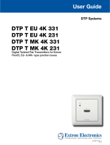
DTP T EU 4K DTP transmitter, and EBP EU button panels.
Kit Contents
Mounting Bracket
and M3 Wafer Head Screws
Mounting Frame
Raceway Space
r
Removal Tool
Extron
Extron
Installation in a Surface Mount Box or Wall Box
Follow these steps to install Flex55 modules in a surface mount box or in a wall box.
NOTE: Some modules are difcult to remove once installed. Make sure the wiring is
correct before snapping in each module at step
3
.
USB STORAGE
MARK
Extron
Extron
RECORD
M3
screws
Secure the mounting bracket
to the box using the provided
M3 screws.
Extron SMB 212
Mounting
Bracket
Mounting
Frame
Position the mounting frame
on the bracket.
Connect cables to the
Flex55 modules and
snap the modules into
the bracket.
Extron Flex55 Modules
1
2
3

Installation in a European Raceway Channel
Follow these steps to install a Flex55 module into a raceway.
Cable
Raceway
Junction Box
Frame
Bracket
Extron Flex55 Module
Secure the raceway spacer and
bracket to the junction box using
the provided M3 screws.
Position the frame on
the bracket.
Connect cables to the
Flex55 module and
snap the module into
the installed bracket.
Raceway
Spacer
(optional)
1
2
3
Removing a Flex55 Module
Follow these steps to remove an installed Flex55 module.
Extron
Extron
Remove the
module.
Locking
Tabs (2)
At the locking tab
locations, insert the
removal tool up to the
arrow.
Removal Tool
Pull the removal tool
to the left to unhook
each locking tab from
the bracket.
Locking
Tab (1)
For modules with one locking tab,
unhook the tab located at the center.
For half modules, the tab is located as
shown below:
Locking
Tab (1)
Extron
Extron
VOLUME
DISPLAY
OFF
ON
PC
Extron
Extron
Extron
Extron
Extron
Extron
1 2 3
68-3060-50
Rev. A
05 17
© 2017 Extron Electronics — All rights reserved. All trademarks mentioned are the property of their respective owners. www.extron.com
/

