Toro CCR 3650 GTS Series User manual
- Category
- Snow throwers
- Type
- User manual

Operator’s Manual
Domestic English (EN)
Form No. 3326-125 Rev A
CCR 2450 GTS
CCR 3650 GTS
Snowthrower
Model No. 38515—220000001 and Up
Model No. 38516—220000001 and Up
Model No. 38517—220000001 and Up
Model No. 38518—220000001 and Up

2
All Rights Reserved
Printed in the USA
2003 by The Toro Company
8111 Lyndale Avenue South
Bloomington, MN 55420-1196
The engine exhaust from this product contains
chemicals known to the State of California to cause
cancer, birth defects, or other reproductive harm.
Warning
Important This engine is not equipped with a spark
arrester muffler. It is a violation of California Public
Resource Code Section 4442 to use or operate this engine
on any forest-covered, brush-covered, or grass-covered
land. Other states or federal areas may have similar laws.
This spark ignition system complies with Canadian
ICES-002.
Ce système d’allumage par étincelle de véhicule est
conforme à la norme NMB-002 du Canada.
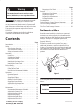
Contents
Page
Introduction 2. . . . . . . . . . . . . . . . . . . . . . . . . . . . . . . . .
Safety 3. . . . . . . . . . . . . . . . . . . . . . . . . . . . . . . . . . . . . .
Safe Operating Practices 3. . . . . . . . . . . . . . . . . . . .
Toro Snowthrower Safety 4. . . . . . . . . . . . . . . . . . .
Safety and Instruction Decals 5. . . . . . . . . . . . . . . . .
Assembly 7. . . . . . . . . . . . . . . . . . . . . . . . . . . . . . . . . . .
Loose Parts 7. . . . . . . . . . . . . . . . . . . . . . . . . . . . . . .
Unfolding the Handle 7. . . . . . . . . . . . . . . . . . . . . . .
Installing the Handle 8. . . . . . . . . . . . . . . . . . . . . . .
Installing the Discharge Chute 9. . . . . . . . . . . . . . . .
Installing the Chute Crank 10. . . . . . . . . . . . . . . . . . .
Before Starting 11. . . . . . . . . . . . . . . . . . . . . . . . . . . . . . .
Mixing Gasoline and Oil 11. . . . . . . . . . . . . . . . . . . .
Filling the Fuel Tank 12. . . . . . . . . . . . . . . . . . . . . . .
Reviewing the Maintenance Schedule 12. . . . . . . . . .
Operation 12. . . . . . . . . . . . . . . . . . . . . . . . . . . . . . . . . . .
Operating Controls 12. . . . . . . . . . . . . . . . . . . . . . . . .
Starting the Engine 12. . . . . . . . . . . . . . . . . . . . . . . . .
Stopping the Engine 13. . . . . . . . . . . . . . . . . . . . . . . .
Starting the Rotor Blades 13. . . . . . . . . . . . . . . . . . . .
Stopping the Rotor Blades 13. . . . . . . . . . . . . . . . . . .
Adjusting the Discharge Chute 13. . . . . . . . . . . . . . .
Snowthrowing Tips 14. . . . . . . . . . . . . . . . . . . . . . . .
Maintenance 15. . . . . . . . . . . . . . . . . . . . . . . . . . . . . . . . .
Recommended Maintenance Schedule 15. . . . . . . . .
Adjusting the Control Cable 16. . . . . . . . . . . . . . . . . .
Replacing the Rotor Blades 17. . . . . . . . . . . . . . . . . .
Replacing the Scraper 19. . . . . . . . . . . . . . . . . . . . . .
Replacing the Spark Plug 19. . . . . . . . . . . . . . . . . . . .
Replacing the Drive Belt 20. . . . . . . . . . . . . . . . . . . .
Page
Emptying the Fuel Tank 20. . . . . . . . . . . . . . . . . . . . .
Storage 21. . . . . . . . . . . . . . . . . . . . . . . . . . . . . . . . . . . . .
Preparing the Fuel System 21. . . . . . . . . . . . . . . . . . .
Preparing the Engine 21. . . . . . . . . . . . . . . . . . . . . . .
Preparing the Snowthrower 21. . . . . . . . . . . . . . . . . .
Folding the Handle 21. . . . . . . . . . . . . . . . . . . . . . . . .
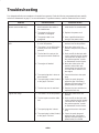
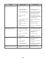
Troubleshooting 22. . . . . . . . . . . . . . . . . . . . . . . . . . . . . .
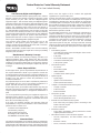
Federal Emission Control Warranty Statement 24. . . . . .
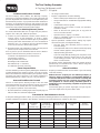
The Toro Starting Guarantee 26. . . . . . . . . . . . . . . . . . . .
The Toro Total Coverage Guarantee 28. . . . . . . . . . . . . .
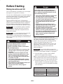
Introduction
Read this manual carefully to learn how to operate and
maintain your product properly. The information in this
manual can help you and others avoid injury and product
damage. Although Toro designs and produces safe
products, you are responsible for operating the product
properly and safely.
Whenever you need service, genuine Toro parts, or
additional information, contact an Authorized Service
Dealer or Toro Customer Service and have the model and
serial numbers of your product ready. Figure 1 illustrates
the location of the model and serial numbers on the
product.
1
m5515
Figure 1
1. Location of the model and serial numbers
Write the product model and serial numbers in the space
below:
Model No.
Serial No.

3
This manual identifies potential hazards and has special
safety messages that help you and others avoid personal
injury and even death. Danger, Warning, and Caution are
signal words used to identify the level of hazard. However,
regardless of the hazard, be extremely careful.
Danger signals an extreme hazard that will cause serious
injury or death if you do not follow the recommended
precautions.
Warning signals a hazard that may cause serious injury or
death if you do not follow the recommended precautions.
Caution signals a hazard that may cause minor or moderate
injury if you do not follow the recommended precautions.
This manual uses 2 other words to highlight information.
Important calls attention to special mechanical
information and Note: emphasizes general information
worthy of special attention.
Safety
Models 38517 and 38518 meet or exceed the B71.3
specifications of the American National Standards
Institute in effect at the time of production.
To ensure maximum safety and best performance, and
to gain knowledge of the product, it is essential that you
and any other operator of the snowthrower read and
understand the contents of this manual before the
engine is ever started.
This is the safety alert symbol. It is used to alert you
to potential personal injury hazards. Obey all safety
messages that follow this symbol to avoid possible
injury or death.
Improperly using or maintaining this snowthrower
could result in injury or death. To reduce this potential,
comply with the following safety instructions.
Safe Operating Practices
The following instructions have been adapted from the
ANSI/OPEI B71.3–1995 standard and the ISO 8437:1989
standard.
Training
• Read the operator’s manual carefully. Be thoroughly
familiar with the controls and the proper use of the
equipment. Know how to stop the unit and disengage
the controls quickly.
• Never allow children to operate the snowthrower. Never
allow adults to operate the snowthrower without proper
instruction.
• Keep the area of operation clear of all persons
(particularly small children) and pets.
• Exercise caution to avoid slipping or falling.
Preparation
• Thoroughly inspect the area where you will use the
snowthrower. Remove all doormats, sleds, boards,
wires, and other foreign objects.
• Release the control bar to disengage the rotor blades
before starting the engine.
• Do not operate the snowthrower without wearing
adequate winter garments. Wear footwear that will
improve your footing on slippery surfaces.
• Handle fuel with care; it is highly flammable.
– Use an approved fuel container.
– Never add fuel to a running or hot engine.
– Fill the fuel tank outdoors with extreme care. Never
fill the fuel tank indoors.
– Replace the fuel tank cap securely and wipe up any
spilled fuel.
• Use only the power cord supplied with the snowthrower
and a receptacle appropriate for use with the power cord
for electric-start motors.
• Never attempt to make any adjustments while the
engine is running, except where specifically
recommended by Toro.
• Let the engine and the snowthrower adjust to the
outdoor temperature before starting to clear snow.
• Operating any powered machine can result in foreign
objects being thrown into the eyes. Always wear safety
glasses or eye shields while operating, adjusting, or
repairing the snowthrower.
Operation
• Do not put hands or feet near or under rotating parts.
Keep clear of the discharge opening at all times.
• Exercise extreme caution when crossing gravel drives,
walks, or roads. Stay alert for hidden hazards or traffic.
• Do not attempt to clear snow from a crushed-rock or
gravel surface. This product is intended for use only on
paved surfaces.
• After striking a foreign object, stop the engine, remove
the ignition key, thoroughly inspect the snowthrower for
any damage, and repair the damage before operating the
snowthrower.
• If the unit should start to vibrate abnormally, stop the
engine and check immediately for the cause. Vibration
is generally a warning of trouble.

4
• Stop the engine whenever you leave the operating
position, before unclogging the discharge chute, and
when making any repairs, adjustments, or inspections.
• When cleaning, repairing, or inspecting, make certain
that the rotor blades and all moving parts have stopped.
• Do not run the engine indoors, except when starting it
and for moving the snowthrower in or out of the
building. Open the outside doors; exhaust fumes are
dangerous.
• Do not clear snow across the face of slopes. Exercise
extreme caution when changing direction on slopes. Do
not attempt to clear steep slopes.
• Never operate the snowthrower without proper guards,
plates, or other safety protective devices in place.
• Never operate the snowthrower near glass enclosures,
automobiles, window wells, and drop-offs without
properly adjusting the snow discharge angle. Keep
children and pets away.
• Do not overload the machine capacity by attempting to
clear snow at too fast a rate.
• Look behind and use care when backing up with the
snowthrower.
• Never direct the discharge at bystanders or allow
anyone in front of the unit.
• Never operate the snowthrower without good visibility
or light. Always be sure of your footing, and keep a
firm hold on the handle. Walk; never run.
Maintenance and Storage
• Check all fasteners at frequent intervals for proper
tightness to be sure that the equipment is in safe
working condition.
• Never store the machine with fuel in the fuel tank inside
a building where ignition sources are present, such as
hot water and space heaters and clothes dryers. Allow
the engine to cool before storing in any enclosure.
• Always refer to this operator’s manual for important
details if the snowthrower is to be stored for an
extended period.
• Maintain or replace safety and instruction labels when
necessary.
Toro Snowthrower Safety
The following list contains safety information specific to
Toro products or other safety information that you must
know.
• Rotating rotor blades can injure fingers or hands. Stay
behind the handles and away from the discharge
opening while operating the snowthrower. Keep your
face, hands, feet, and any other part of your body or
clothing away from moving or rotating parts.
• Before adjusting, cleaning, repairing, and inspecting the
snowthrower, and before unclogging the discharge
chute, stop the engine, remove the key, and wait for all
moving parts to stop.
• Use a stick, not your hands, to remove obstructions
from the discharge chute.
• Before leaving the operating position, stop the engine,
remove the key, and wait for all moving parts to stop.
• Do not wear loose-fitting clothing that could get caught
in moving parts.
• If a shield, safety device, or decal is damaged, illegible,
or lost, repair or replace it before beginning operation.
Also, tighten any loose fasteners.
• Do not smoke while handling gasoline.
• Do not use the snowthrower on a roof.
• Do not touch the engine while it is running or soon after
it has stopped because the engine may be hot enough to
cause a burn.
• Perform only those maintenance instructions described
in this manual. Before performing any maintenance,
service, or adjustment, stop the engine, remove the key,
and disconnect the wire from the spark plug. If major
repairs are ever needed, contact your Authorized
Service Dealer.
• Do not change the governor settings on the engine.
• When storing the snowthrower for more than 30 days,
drain the fuel from the fuel tank to prevent a potential
hazard. Store fuel in an approved fuel container.
Remove the key from the ignition switch before storing
the snowthrower.
• To ensure the best performance and safety, purchase
only genuine Toro replacement parts and accessories.

5
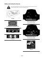
Safety and Instruction Decals
Safety decals and instructions are easily visible to the operator and are located near any area
of potential danger. Replace any decal that is damaged or lost.
60-9480
61-4790 (Electric-start models only)
104-2767
104-2775
105-3521 (Model 38515) or
105-1955 (Model 38517)
105-3523 (Model 38516) or
105-1954 (Model 38518)
104-4135

6
French translation of
U.S. EPA decal text:
Ce moteur est conforme à la
réglementation antipollution
Phase EPA relative aux moteurs
ULGE.
Famille : XXXXX.XXXXXX
Nº de modèle :
XXX–XXXX
CYLINDREE (CC) : 141
Pour plus de détails sur la
sécurité, l’entretien et les
réglages, reportez-vous au
manuel de l’utilisateur. Nº de
téléphone des services de vente
et d’après-vente aux Etats-Unis :
1-800-526-6937
The Toro Company
Bloomington, MN
INFORMATION
IMPORTANTE
CONCERNANT LE MOTEUR

7
Assembly
Note: Determine the left and right sides of the machine from the normal operating position.
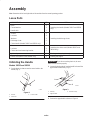
Loose Parts
DESCRIPTION QTY. USE
Knob
Curved washer
Handle lock
1
1
1
Installing the handle (Models 38517 and 38518
only)
Screws
Locknuts
Washers
Discharge chute
Chute handle (Models 38515 and 38516 only)
3
3
3
1
1
Installing the discharge chute
Bolts
Locknuts
Chute crank and mounting bracket
2
2
1
Installing the chute crank (Models 38517 and
38518 only)
Ignition key 1 Starting and stopping the engine
Power cord (electric-start models only) 1 Starting the engine
Unfolding the Handle
Models 38515 and 38516
1. Cut the plastic tie that secures the control cable to the
handle (Fig. 2).
1
2
3
m5536
Figure 2
1. Handle
2. Plastic tie
3. Control cable
Important
If you do not cut the plastic tie, the rotor
brake will not function properly.
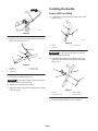
2. Loosen the knobs and pull out the handle locks until the
upper handle rotates freely (Fig. 3).
m4523a
1
2
3
Figure 3
1. Knob (2)
2. Upper handle
3. Handle lock (2)
3. Position the upper handle as shown in Figure 4.

8
m5516
Figure 4
4. Insert the loose end of the control cable into the bottom
hole in the control bar (Fig. 5).
1
3
2
5
4
m5533
Figure 5
1. Top hole
2. Bottom hole
3. Control bar
4. Spring cover
5. Control cable
5. Fully insert the handle locks (Fig. 3).
Important Ensure that the control cable is not pinched
by the upper handle or the handle lock.
6. Tighten the knobs until they are snug.
7. Adjust the control cable. Refer to Adjusting the Control
Cable on page 16.
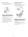
Installing the Handle
Models 38517 and 38518
1. Cut the plastic tie that secures the control cable to the
handle (Fig. 6).
1
2
3
m5536
Figure 6
1. Handle
2. Plastic tie
3. Control cable
Important If you do not cut the plastic tie, the rotor
brake will not function properly.
2. Loosen the knob and pull out the handle lock on the
right side of the handle until the upper handle rotates
freely (Fig. 7).
1
2
4
3
Figure 7
1. Knob (2)
2. Curved washer (2)
3. Upper handle
4. Handle lock (2)
3. Position the upper handle as shown in Figure 8.

9
m5516
Figure 8
4. Loosely install the handle lock, curved washer, and
knob on the left side of the handle as shown in Figure 7.
Note: Ensure that the curved side of the curved washer
is against the handle.
5. Insert the loose end of the control cable into the bottom
hole in the control bar (Fig. 9).
m-5519
4
3
2
1
Figure 9
1. Control cable
2. Control bar
3. Top hole
4. Bottom hole
6. Fully insert the handle locks (Fig. 3).
Important Ensure that the control cable is not pinched
by the upper handle or the handle lock.
7. Tighten the knobs until they are snug.
8. Adjust the control cable. Refer to Adjusting the Control
Cable on page 16.
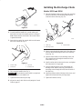
Installing the Discharge Chute
Models 38515 and 38516
1. Place the discharge chute over the chute ring, and align
the hole in the back of the discharge chute with the
center hole in the chute ring (Fig. 10).
1
2
3
m5520
Figure 10
1. Chute ring
2. Discharge chute
3. Chute handle
2. Insert a screw through the center hole of the chute ring
from the inside and through the hole in the discharge
chute (Fig. 10).
3. Insert the chute handle over the discharge chute, and
fully insert the screw through the center hole in the
chute handle (Fig. 10).
4. Install a washer and a locknut on the screw, and tighten
the locknut until it is finger tight.
5. Align the remaining holes of the chute handle, the
discharge chute, and the chute ring, and insert the 2
remaining screws through the holes from the inside of
the chute ring.
6. Install the washers and the locknuts on the screws, and
tighten the locknuts until they are finger tight.
7. Tighten all locknuts securely.

10
Models 38517 and 38518
1. Place the discharge chute over the chute ring, and align
the hole in the back of the discharge chute with the
center hole in the chute ring (Fig. 11).
1
2
m5520
Figure 11
1. Chute ring 2. Discharge chute
2. Insert a screw through the center hole of the chute ring
from the inside and through the hole in the discharge
chute (Fig. 11).
3. Install a washer and a locknut on the screw, and tighten
the locknut until it is finger tight.
4. Align the remaining holes of the discharge chute and
the chute ring, and insert the 2 remaining screws
through the holes from the inside of the chute ring.
5. Install the washers and the locknuts on the screws, and
tighten the locknuts until they are finger tight.
6. Tighten all locknuts securely.
Installing the Chute Crank
Models 38517 and 38518
1. Insert the flattened end of the chute crank through the
hole in the shroud while aligning the mounting bracket
with the holes in the lower handle (Fig. 12).
2
1
3
m5545
Figure 12
1. Chute crank
2. Plastic bushing
3. Mounting bracket
2. Slowly rotate the crank until the flattened end fits into
the hidden gear opening and the chute ring turns with
the crank (Fig. 12).
3. Ensure that the plastic bushing is fully inserted into the
hole in the mounting bracket. If not, slide it along the
crank and into the hole (Fig. 12).
4. Secure the mounting bracket to the handle with 2 bolts
and locknuts (Fig. 12).

11
Before Starting
Mixing Gasoline and Oil
Your Toro snowthrower is powered by a two-cycle engine
that requires a 50:1 gasoline-to-oil mixture.
Use only clean, unleaded gasoline no more than 30 days old
and with an octane rating of 87 or higher. Using unleaded
gasoline reduces combustion chamber deposits and
promotes longer spark plug life.
Engines certified to comply with U.S. EPA emission
regulations for ULGE engines are certified to operate on a
mixture of regular unleaded gasoline and oil, include the
following emission control system(s): EM and TWC (if
equipped), and do not include any user-adjustable features.
Important Do not use methanol, gasoline containing
methanol, gasohol containing more than 10% ethanol,
premium gasoline, or white gas. Using these fuels can
damage the fuel system.
Important Do not use an automotive oil (such as SAE
30 or 10W30), a two-cycle oil that is not NMMA
TCW-certified, or a fuel mixed at the wrong gasoline-to-oil
ratio. This can cause engine damage not covered under the
Toro warranty.
Danger
In certain conditions, gasoline is extremely
flammable and highly explosive. A fire or
explosion from gasoline can burn you and others
and can damage property.
• Fill the fuel tank outdoors, in an open area, and
when the engine is cold. Wipe up any gasoline
that spills.
• Do not fill the fuel tank completely full. Add
gasoline to the fuel tank until the level is 1/4 to
1/2 in. (6 to 13 mm) below the bottom of the
filler neck. This empty space in the tank allows
the gasoline to expand.
• Never smoke when handling gasoline, and stay
away from an open flame or where a spark may
ignite the gasoline fumes.
• Store gasoline in an approved fuel container and
keep it out of the reach of children.
• Never buy more than a 30-day supply of
gasoline.
Danger
When fueling, under certain circumstances, a
static charge can develop, igniting the gasoline. A
fire or explosion from gasoline can burn you and
others and damage property.
• Always place gasoline containers on the ground
and away from your vehicle before filling.
• Do not fill gasoline containers inside a vehicle or
on a truck or trailer bed because interior
carpets or plastic truck bed liners may insulate
the container and slow the loss of any static
charge.
• When practical, remove gasoline-powered
equipment from the truck or trailer and refuel
the equipment with its wheels on the ground.
• If this is not possible, then refuel such
equipment on a truck or trailer from a portable
container, not from a gasoline dispenser nozzle.
• If you must use a gasoline dispenser nozzle, keep
the nozzle in contact with the rim of the fuel
tank or container opening at all times until
fueling is complete.
Note: Use a fuel stabilizer/conditioner for all Toro
gasoline-powered products during operation and storage. A
fuel stabilizer/conditioner cleans the engine during
operation and prevents gum-like varnish deposits from
forming in the engine during storage. A fuel
stabilizer/conditioner works best when you mix it with
fresh gasoline. If you use Toro 50:1 2-Cycle Oil (Fuel
Stabilizer Added), you do not need to add a fuel
stabilizer/conditioner.
Important Do not use fuel additives except a fuel
stabilizer during storage. Do not use fuel stabilizers with an
alcohol base, such as ethanol, methanol, or isopropanol.
1. Pour a half gallon (1.9 liters) of fresh, unleaded
gasoline into an approved fuel container.
Note: Do not mix gasoline and oil in the fuel tank. Oil at
room temperature mixes easier and more thoroughly than
cold oil. Oil below 32°F (0°C) requires additional mixing.
2. Add the full amount of Toro 50:1 2-Cycle Oil (Fuel
Stabilizer Added) or an equivalent high grade, NMMA
TCW-certified two-cycle oil to the gasoline according
to the chart below:
50:1 Gasoline-to-Oil Ratio Mixing Chart
Gasoline Oil
1 gallon (4 liters) 2.6 ounces (80 ml)
2 gallons (8 liters) 5.2 ounces (160 ml)
5 gallons (20 liters) 13 ounces (400 ml)

12
3. Install the cap on the fuel container.
4. Shake the container to mix the gasoline and oil
thoroughly.
5. Slowly remove the cap and add the remaining amount
of gasoline.
Filling the Fuel Tank
Important Do not overfill the fuel tank. The
gasoline-and-oil mixture must have room to expand.
1. Clean around the fuel tank cap; do not allow snow or
water to enter the fuel tank.
2. Remove the fuel tank cap and fill the fuel tank with the
gasoline-and-oil mixture until the level is 1/4 to 1/2 in.
(6 to 13 mm) below the bottom of the filler neck. Do
not fill into the filler neck.
3. Install the fuel tank cap securely and wipe up any
spilled fuel.
Reviewing the Maintenance
Schedule
Review the Recommended Maintenance Schedule on
page 15. You may need to perform one or more additional
procedures before or soon after you begin operating the
snowthrower.
Operation
Note: Determine the left and right sides of the machine
from the normal operating position.
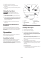
Operating Controls
The snowthrower control panel contains a key switch, a
primer, a recoil starter, and an electric-start button
(electric-start models only). The choke lever and the cord
connection (for the electric-start models) are located below
the control panel as shown in Figure 13.
1
2
3
4
5
6
m5544
Figure 13
1. Key switch
2. Primer
3. Electric-start button
(electric-start models
only)
4. Recoil start
5. Cord connection
(electric-start models
only; below the control
panel)
6. Choke lever
Starting the Engine
1. Turn the key to the On position.
2. Move the choke lever to the right.
3. Cover the hole in the center of the primer with your
thumb and push the primer in twice, pausing a moment
between pushes. In extremely cold temperatures, repeat
this step if necessary.
Note: Take off your glove when you push in the primer
so that air cannot escape from the primer hole.
Note: Do not use the choke or the primer when starting
a warm engine.
4. Start the engine by doing the following:
For a recoil starter: Hold the snowthrower handle with
one hand and pull the recoil starter vigorously with the
other hand.
For an electric starter:
A. Connect the power cord to the snowthrower and to a
standard household power outlet.

13
Caution
If you leave the snowthrower plugged into a power
outlet, someone can inadvertently start the
snowthrower and injure people or damage
property.
Unplug the power cord whenever you are not
starting the snowthrower.
B. Push the starter button.
Note: Run the electric starter no more than 10 times at
intervals of 5 seconds on, then 5 seconds off.
Important Running the electric starter extensively can
overheat and damage it.
Note: If the engine does not start after this series of
attempts, wait at least 40 minutes to allow the starter to
cool before attempting to start it again.
Note: If the engine does not start after the second series
of attempts, take the snowthrower to an Authorized
Service Dealer for service.
C. When the engine starts, disconnect the power cord
from the snowthrower and the outlet.
5. With the engine running, move the choke lever to the
left slowly.
Stopping the Engine
Turn the key to the Off position and wait for all moving
parts to stop before leaving the operating position.
Starting the Rotor Blades
To start the rotor blades, squeeze the control bar and the
handle together.
Stopping the Rotor Blades
To stop the rotor blades, release the control bar.
Note: When you release the control bar, the rotor blades
stop, but the engine continues to run.
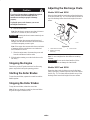
Adjusting the Discharge Chute
Models 38515 and 38516
Move the chute handle left and right to adjust the direction
of the snow stream (Fig. 14). The chute deflector handle on
top of the discharge chute controls the height of the snow
stream.
1
2
3
m5524
Figure 14
1. Chute deflector handle
2. Deflector mounting
locknut (2)
3. Chute handle
Note: Do not overtighten the chute deflector mounting
locknuts.
Important Do not use the chute handle to lift the
snowthrower. This can damage the chute handle.
Models 38517 and 38518
Rotate the chute crank clockwise to move the discharge
chute to the right or counterclockwise to move the chute to
the left (Fig. 15). The chute deflector handle on top of the
discharge chute controls the height of the snow stream.

14
1
2
3
m5542
Figure 15
1. Chute deflector handle
2. Deflector mounting
locknut (2)
3. Chute crank
Note: Do not overtighten the chute deflector mounting
locknuts.
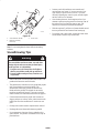
Snowthrowing Tips
Warning
The rotor blades can throw stones, toys and other
foreign objects and cause serious personal injury
to the operator or to bystanders.
• Keep the area to be cleared free of all objects
that the rotor blades could pick up and throw.
• Keep all children and pets away from the area
of operation.
• Remove the snow as soon as possible after it falls. This
produces the best snow removal results.
• The snowthrower clears down to the ground and propels
itself forward when you raise the handle. The
snowthrower tilts slightly forward so that the rotor
blades strike the ground. The wheels do not need to
touch the ground to self-propel. The more you tilt the
handle forward, the faster the snowthrower self-propels.
• If the snowthrower does not propel itself forward on
slippery surfaces or in heavy snow, push forward on the
handle, but allow the snowthrower to work at its own
pace.
• Overlap each swath to ensure complete snow removal.
• Discharge the snow downwind whenever possible.
• Do not attempt to clear snow from a crushed-rock or
gravel surface. This product is intended for use only on
paved surfaces.
• In snowy and cold conditions, some controls and
moving parts may freeze. Do not use excessive force
when trying to operate frozen controls. If you have
difficulty operating any control or part, start the engine
and let it run for a few minutes.
• After clearing the snow, let the engine run for a few
minutes to prevent moving parts from freezing. Shut off
the engine, wait for all moving parts to stop, and
remove all ice and snow from the snowthrower.
• With the engine off, pull the recoil starter handle several
times to prevent the recoil starter from freezing up.
• For models with a chute crank, operate the chute crank
several times to remove any ice and snow.

15
Maintenance
Note: Determine the left and right sides of the machine from the normal operating position.
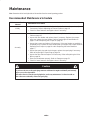
Recommended Maintenance Schedule
Maintenance Service
Interval
Maintenance Procedure
Initially
• Check the control cable both initially and after the first hour of operation; adjust it
if necessary. Refer to Adjusting the Control Cable on page 16.
• Check for loose fasteners and tighten them if necessary.
Annually
• Check the control cable and adjust it if necessary. Refer to Adjusting the Control
Cable on page 16.
• Inspect the rotor blades and replace them if necessary. Replace the scraper
when you replace the rotor blades. Refer to Replacing the Rotor Blades on
page 17 and to Replacing the Scraper on page 19.
• Inspect the scraper and replace it if necessary. If the rotor blades are partially or
completely worn, replace the rotor blades when you replace the scraper. Refer to
Replacing the Scraper on page 19 and to Replacing the Rotor Blades on
page 17.
• Inspect the spark plug and check the gap; replace the spark plug if necessary.
Refer to Replacing the Spark Plug on page 19.
• Inspect the drive belt and replace it if necessary. Refer to Replacing the Drive
Belt on page 20.
• Store the snowthrower properly. Refer to Storage on page 21.
• Check for loose fasteners and tighten them if necessary.
Caution
If you leave the wire on the spark plug, someone could start the engine accidentally and seriously
injure you or other bystanders.
Disconnect the wire from the spark plug before you do any maintenance. Set the wire aside so
that it does not accidentally contact the spark plug.

16
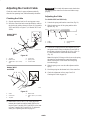
Adjusting the Control Cable
Check the control cable for proper adjustment initially,
after the first operating hour, and then annually thereafter.
Checking the Cable
1. Stop the engine and wait for all moving parts to stop.
2. Move the control bar back toward the handle to remove
the slack in the cable as shown in Figure 16 (for models
38515 and 38516) or Figure 17 (for models 38517 and
38518).
1
2
5
4
m-5533/m-2708
1
2
3
6
4
Models 38515
and 38516
Figure 16
1. Top hole
2. Bottom hole
3. 1/16 to 1/8 in. (2 to 3 mm)
gap
4. Control bar
5. Spring cover
6. Control cable
m-5519
4
3
2
1
5
Models 38517
and 38518
Figure 17
1. Cable
2. Control bar
3. Top hole
4. Bottom hole
5. 1/16 to 1/8 in. (2 to 3 mm)
gap
3. Ensure that a 1/16 to 1/8 in. (2 to 3 mm) gap exists
between the control bar and the handle. Refer to the
inset in Figure 5 (models 38515 and 38516) or the inset
in Figure 9 (models 38517 and 38518). To adjust the
cable, go to Adjusting the Cable on page 16.
Important The control cable must contain slack when
you disengage the control bar for the rotor blades to stop
properly.
Adjusting the Cable
For Models 38515 and 38516 only:
1. Unhook the spring end from the control bar (Fig. 16).
2. Slide the spring cover off the spring and the cable
adjuster (Fig. 18).
897
1
2
34
Figure 18
1. Cable
2. Z-fitting
3. Cable adjuster
4. Spring
3. Unhook the Z-fitting from the cable adjuster (Fig. 18)
and position the Z-fitting in a higher or lower hole on
the adjuster to obtain a proper gap of 1/16 to 1/8 in. (2
to 3 mm) between the control bar and the handle
(Fig. 16).
Note: Moving the Z-fitting to a hole closer to the spring
decreases the gap between the control bar and the
handle; moving it to a hole farther from the spring
increases the gap.
4. Slide the spring cover over the cable adjuster and the
spring.
5. Hook the spring into the bottom hole of the control bar.
6. Check the adjustment (refer to steps 2 and 3 of
Checking the Cable on page 16).

17
For Models 38517 and 38518:
1. Unhook the upper cable end from the hole in the control
bar (Fig. 17).
2. Slide the spring cover up the cable to expose the cable
adjuster (Fig. 19).
1
2
3
Figure 19
1. Cable adjuster
2. Z-fitting
3. Spring cover
3. Unhook the Z-fitting from the cable adjuster (Fig. 18)
and position it in a higher or lower hole on the adjuster
to obtain a gap of 1/16 to 1/8 in. (2 to 3 mm) between
the control bar and the handle (Fig. 9).
Note: Moving the Z-fitting to a hole closer to the spring
decreases the gap between the control bar and the
handle; moving it to a hole farther from the spring
increases the gap.
4. Slide the spring cover over the cable adjuster.
5. Install the upper cable end into the bottom hole in the
control bar.
6. Check the adjustment (refer to steps 2 and 3 of
Checking the Cable on page 16).
After extended use, the drive belt may wear and lose its
proper belt tension. Improper belt tension causes the belt to
slip and decreases the performance under a heavy load. Belt
slippage may occur after 2 or 3 seasons of normal usage (10
to 15 hours). If the drive belt slips (continuously squeals)
under a heavy load, increase the belt tension by inserting
the spring end into the top hole of the control bar (Fig. 16
or Fig. 17).
Note: Using the incorrect adjusting hole can reduce the
drive belt life. Occasional belt slippage (squealing) may
occur in extremely wet conditions due to moisture in the
drive system. To remove moisture, start the rotor and
operate it without a load for 30 seconds. Once you remove
the moisture, the drive belt should not slip.
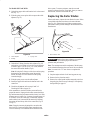
Replacing the Rotor Blades
Before each season, inspect the rotor blades for wear. When
a rotor blade edge has worn down to the wear indicator
hole (Fig. 20), replace both rotor blades to ensure proper
performance and to prevent damage to the underside of the
snowthrower.
m-5538a
1
Figure 20
1. Wear indicator hole
Important Replace the scraper whenever you replace
the rotor blades. This ensures proper snowthrower
operation and performance.
Note: The running time and the roughness of the driveway
or the sidewalk determines the wear rate of the rotor blades.
Note: You need a No. T27 torx driver to complete this
procedure.
1. Stop the engine and wait for all moving parts to stop.
2. Remove the key from the switch.
3. Remove the control panel and disconnect the wire from
the spark plug. Refer to steps 3 through 5 of Replacing
the Spark Plug on page 19.

18
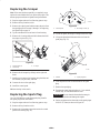
Removing the Old Rotor Blades
1. Remove the 4 torx screws and the 4 locknuts that secure
the outer edges of the rotor blade to the rotor assembly
(Fig. 21).
1
2
3
4
4
5
6
7
8
680
Figure 21
1. Rotor blade (2)
2. Rotor half (2)
3. Torx screw (8)
4. Locknuts (13)
5. Hex-head bolts (4)
6. Spacer (4)
7. Rotor assembly
8. Long hex-head bolt
2. Remove the 2 hex-head bolts and 2 locknuts that secure
the center of the blade to the rotor halves (Fig. 21).
3. Loosen the long hex-head bolt that secures the rotor
halves to the auger shaft assembly (Fig. 21).
4. Slide the rotor blade out from between the rotor halves
(Fig. 21).
5. Remove the 2 spacers from the old rotor blade and
install the spacers in a new rotor blade.
Installing a New Rotor Blade
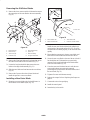
1. Examine a new rotor blade edge for the difference in
the thickness of the rubber layers (Fig. 22).
m-5538a/m-5059
1
2
3
4
Figure 22
1. Thick rubber side
2. Wear indicator hole
3. Thin rubber side
4. Inside of curved surface
Install the new rotor blade with the thick rubber layer
on the inside of the curved surface (Fig. 22). If you do
not install the rotor blade properly, it will wear out more
quickly.
2. Ensure that the spacers are in the new rotor blade, and
insert the new rotor blade between the rotor halves.
3. Secure the new rotor blade to the rotor halves with the 2
hex-head bolts and 2 locknuts that you previously
removed. Position the bolt heads on the thick rubber
side of the rotor blade (Fig. 22).
4. Curve the new rotor blade and secure it with the torx
screws and locknuts you previously removed,
positioning the screw heads on the thick rubber side of
the rotor blade (Fig. 22).
5. Tighten all screws and locknuts securely.
6. Replace the scraper. Refer to Replacing the Scraper on
page 19.
7. Connect the wire to the spark plug.
8. Install the control panel.
9. Insert the key in the switch.

19
Replacing the Scraper
Note: If the rotor blades are partially or completely worn,
replace the rotor blades when you replace the scraper. This
ensures proper snowthrower operation and performance.
1. Stop the engine and wait for all moving parts to stop.
2. Remove the key from the switch.
3. Remove the control panel and disconnect the wire from
the spark plug. Refer to steps 3 through 5 of Replacing
the Spark Plug on page 19.
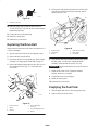
4. Tip the snowthrower forward onto its front housing.
5. Remove the 3 carriage bolts and the locknuts that hold
the scraper in place (Fig. 23).
1
2
3
m-5535
Figure 23
1. Carriage bolt (3)
2. Locknut (3)
3. Scraper
6. Remove the old scraper by sliding it to the right and
down.
7. Install a new scraper to the housing using the bolts and
the locknuts you previously removed.
8. Connect the wire to the spark plug.
9. Install the control panel.
10.Insert the key in the switch.
Replacing the Spark Plug
Use a NGK BPMR4A or equivalent spark plug. Install a
new spark plug before each season.
1. Stop the engine and wait for all moving parts to stop.
2. Remove the key from the switch.
3. Remove the 3 mounting screws that secure the control
panel to the housing (Fig. 24).
1
2
m-5061a
Figure 24
1. Control panel 2. Mounting screws (3)
4. Lift off the panel, allowing it to hang on the recoil rope.
5. Lift up the shroud and disconnect the wire from the
spark plug (Fig. 25).
1
2
m-5529
Figure 25
1. Shroud 2. Spark-plug wire
6. Clean any debris from around the base of the spark
plug.
7. Remove the spark plug.
8. Examine the spark plug and replace it if it is cracked,
fouled, dirty, or if the electrodes are worn.
Important Do not clean the electrodes because grit
could enter the cylinder and damage the engine.
9. Set the gap between the electrodes on the spark plug at
0.030 in. (0.76 mm) as shown in Figure 26.

20
1
m-3215
Figure 26
1. 0.030 in. (0.76 mm)
10.Install the spark plug by hand and then torque it to
15 ft-lb (20.4 Nm). If you do not have a torque wrench,
tighten the plug firmly.
11. Connect the wire to the spark plug.
12.Install the control panel.
13.Insert the key in the switch.
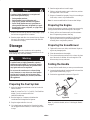
Replacing the Drive Belt
Inspect the drive belt before each season, and replace it if it
is worn or damaged.
1. Stop the engine and wait for all moving parts to stop.
2. Remove the key from the switch.
3. Disconnect the wire from the spark plug. Refer to steps
3 through 5 of Replacing the Spark Plug on page 19.
4. Remove the fasteners that secure the drive belt cover to
the snowthrower frame (Fig. 27). Set the drive belt
cover aside.
1
3
4
2
m-5534
5
6
Figure 27
1. Drive belt cover
2. Nut (2)
3. Washer
4. Short self-tapping
screw (2)
5. Long self-tapping screw
6. Bolt (2)
5. Pull up on the idler pulley and remove the old drive belt
from the rotor pulley, the brake arm assembly, and the
engine pulley (Fig. 28).
4
2
1
6
3
5
626
Figure 28
1. Engine pulley
2. Idler pulley
3. Roller
4. Brake arm assembly
5. Rotor pulley
6. Belt guide
6. Loop the new drive belt around the engine pulley, under
the idler pulley, over the roller, through the brake
assembly, and around the rotor pulley (Fig. 28).
Important The drive belt must be on top of the roller as
shown in Figure 28.
7. Install the drive belt cover. Tighten the fasteners
securely, but do not overtighten.
8. Connect the wire to the spark plug.
9. Install the control panel.
10.Insert the key in the switch.
Emptying the Fuel Tank
1. Stop the engine and wait for all moving parts to stop.
2. Remove the key from the switch.
Page is loading ...
Page is loading ...
Page is loading ...
Page is loading ...
Page is loading ...
Page is loading ...
Page is loading ...
Page is loading ...
-
 1
1
-
 2
2
-
 3
3
-
 4
4
-
 5
5
-
 6
6
-
 7
7
-
 8
8
-
 9
9
-
 10
10
-
 11
11
-
 12
12
-
 13
13
-
 14
14
-
 15
15
-
 16
16
-
 17
17
-
 18
18
-
 19
19
-
 20
20
-
 21
21
-
 22
22
-
 23
23
-
 24
24
-
 25
25
-
 26
26
-
 27
27
-
 28
28


Toro CCR 3650 GTS Series User manual
- Category
- Snow throwers
- Type
- User manual
Ask a question and I''ll find the answer in the document
Finding information in a document is now easier with AI
Related papers
-
Toro Powerlite Snowthrower User manual
-
Toro Power Clear 721 R-C Commercial Snowthrower User manual
-
Toro CCR 3650 GTS Snowthrower User manual
-
-
-
-
Toro Power Clear 721 QZE Snowthrower User manual
-
-
-