Toro CCR Powerlite Snowthrower User manual
- Category
- Snow throwers
- Type
- User manual
Toro CCR Powerlite Snowthrower efficiently clears snow from driveways, walkways, and other areas around your home. Its powerful engine and durable construction make it ideal for tackling even the toughest snowfalls. The snowthrower features a variety of adjustable settings, allowing you to customize your snow-clearing experience. With its user-friendly controls and simple operation, the Toro CCR Powerlite Snowthrower is the perfect choice for homeowners who want to keep their property clear of snow without any hassle.
Toro CCR Powerlite Snowthrower efficiently clears snow from driveways, walkways, and other areas around your home. Its powerful engine and durable construction make it ideal for tackling even the toughest snowfalls. The snowthrower features a variety of adjustable settings, allowing you to customize your snow-clearing experience. With its user-friendly controls and simple operation, the Toro CCR Powerlite Snowthrower is the perfect choice for homeowners who want to keep their property clear of snow without any hassle.


-
 1
1
-
 2
2
-
 3
3
-
 4
4
-
 5
5
-
 6
6
-
 7
7
-
 8
8
-
 9
9
-
 10
10
-
 11
11
-
 12
12
-
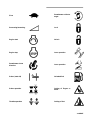 13
13
-
 14
14
-
 15
15
-
 16
16
-
 17
17
-
 18
18
-
 19
19
-
 20
20
-
 21
21
-
 22
22
-
 23
23
-
 24
24


Toro CCR Powerlite Snowthrower User manual
- Category
- Snow throwers
- Type
- User manual
Toro CCR Powerlite Snowthrower efficiently clears snow from driveways, walkways, and other areas around your home. Its powerful engine and durable construction make it ideal for tackling even the toughest snowfalls. The snowthrower features a variety of adjustable settings, allowing you to customize your snow-clearing experience. With its user-friendly controls and simple operation, the Toro CCR Powerlite Snowthrower is the perfect choice for homeowners who want to keep their property clear of snow without any hassle.
Ask a question and I''ll find the answer in the document
Finding information in a document is now easier with AI
Related papers
-
Toro CCR Powerlite Snowthrower User manual
-
Toro CCR 2450 Snowthrower User manual
-
-
-
-
-
Toro Powerlite Snowthrower User manual
-
-
Toro 38537 User manual
-