Follett 00119628R01 User manual
- Category
- Ice cube makers
- Type
- User manual
This manual is also suitable for
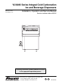
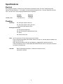
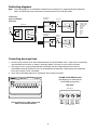
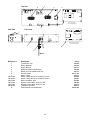
Follett 00119628R01 is an ice and beverage dispenser that offers integral cold carbonation and can be used to dispense both ice and beverages. It features a left-hand ice chute and push-button valve actuation, with eight valves for dispensing a variety of beverages. The dispenser has a 115V, 60Hz, 1 phase electrical requirement and requires a separate circuit with electrical disconnect within 10 ft (6m). It also requires a 3/4" PVC pipe nipple for bin drain, a 3/4" PVC pipe nipple for drain pan drain, and a 1" ID hose for beverage bath drain.
Follett 00119628R01 is an ice and beverage dispenser that offers integral cold carbonation and can be used to dispense both ice and beverages. It features a left-hand ice chute and push-button valve actuation, with eight valves for dispensing a variety of beverages. The dispenser has a 115V, 60Hz, 1 phase electrical requirement and requires a separate circuit with electrical disconnect within 10 ft (6m). It also requires a 3/4" PVC pipe nipple for bin drain, a 3/4" PVC pipe nipple for drain pan drain, and a 1" ID hose for beverage bath drain.


-
 1
1
-
 2
2
-
 3
3
-
 4
4
-
 5
5
-
 6
6
-
 7
7
-
 8
8
-
 9
9
-
 10
10
-
 11
11
-
 12
12
-
 13
13
-
 14
14
-
 15
15
-
 16
16
-
 17
17
-
 18
18
-
 19
19
-
 20
20
-
 21
21
-
 22
22
-
 23
23
-
 24
24


Follett 00119628R01 User manual
- Category
- Ice cube makers
- Type
- User manual
- This manual is also suitable for
Follett 00119628R01 is an ice and beverage dispenser that offers integral cold carbonation and can be used to dispense both ice and beverages. It features a left-hand ice chute and push-button valve actuation, with eight valves for dispensing a variety of beverages. The dispenser has a 115V, 60Hz, 1 phase electrical requirement and requires a separate circuit with electrical disconnect within 10 ft (6m). It also requires a 3/4" PVC pipe nipple for bin drain, a 3/4" PVC pipe nipple for drain pan drain, and a 1" ID hose for beverage bath drain.
Ask a question and I''ll find the answer in the document
Finding information in a document is now easier with AI
Related papers
-
Follett VU300K Series Installation, Operation & Service Manual
-
-
Follett VU155 Series Installation, Operation And Service Manual
-
-
-
-
-
-
-
Other documents
-
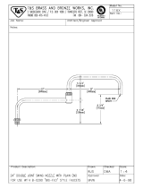 T & S Brass & Bronze Works 116X Datasheet
-
MULTIPLEX CEV Purge Tube Routning (5030476) Installation guide
-
-
-
 IMI Cornelius, Inc. PR150 BC Operating instructions
-
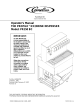 Cornelius PR150 User manual
-
-
Manitowoc SU1024YC Troubleshooting guide
-
-
 IMI Cornelius, Inc. ED250 PRO GATE Operating instructions


