Page is loading ...

LED Ceiling Fan
54in(x.xxm)
MODEL: 16371
ITM./ART. : XXXXXX
120V 60Hz, MADE IN CHINA
User Manual
Customer Assistance
1-866-885-4649
Contact a qualified electrician or call the Customer Care Service Team at 1-866-885-4649
Customer Service hours of operation are 9:00AM-5:00PM EST -Monday-Friday

2
Safety rules
1. To reduce the risk of electric shock, insure electricity has
been turned off at the circuit breaker or fuse box before
beginning.
2. All wiring must be in accordance with the latest edition of
National Electrical Code “ANSI / NFPA 70” and local electrical
codes.
3. WARNING: to reduce the risk of electrical shock or fire, do
not use this fan with any solid-state fan speed control device.
It will permanently damage the electronic circuitry.
4. CAUTION: to reduce the risk of personal injury, use only
the screws provided with the outlet box.
5. The outlet box and support structure must be securely
mounted and capable of reliably supporting a minimum of
15.9 kg (35 lb.). Use only UL Listed outlet boxes marked “FOR
FAN SUPPORT”
6. The fan must be mounted with a minimum of 7 feet
clearance from the trailing edge of the blades to the floor.
7. Avoid placing objects in the path of the blades.
8. To avoid personal injury or damage to th fan and other
items, be cautious when working around or cleaning the fan.
9. Do not use water or detergents when cleaning the fan or
fan blades. A dry dust cloth or lightly damped cloth will be
suitable for cleaning.
10. After making electrical connections, spliced conductors
should be turned upward and pushed carefully up into
the outlet box. The wires should be spread apart with
the grounded conductor and the equipment-grounding
conductor on one side of the outlet box and ungrounded
conductor on the other side of the outlet box.
11. All set screws must be checked and re-tightened where
necessary before installation.
WARNING: to reduce the risk of
fire, electric shock or personal
injury, mount fan to outlet box
marked acceptable for fan
support the screws provided
with the outlet box.
WARNING: to reduce the risk
of personal injury, do not bend
the blade arms (also referred
to as flanges), when installing
the brackets, balancing the
blades or cleaning the fan. Do
not insert foreign objects in-
between rotating fan blades.
WARNING: to reduce the risk of
fire, electric shock or personal
injury, mount to outlet box
marked “acceptable for fan
support of 15.9 kg (35 lbs.) or
less” and use mounting screws
provided with the outlet box.
Most outlet boxes commonly
used for the support of light
fixtures are not acceptable for
fan support and may need to be
replaced. Due to the complexity
of the installation of this fan, a
qualified licensed electrician is
strongly recommended.

3
Basic guidelines for working with electricity
1. Before working on a circuit, go to the main service panel
and remove the fuse or trip the breaker that controls that
circuit.
2. Tape a sign to the panel warning others to leave the circuit
alone while you work
3. Before touching any wire, use a voltage tester to make
sure it’s not live.
4. Whenever you check for voltage in a receptacle, check
both outlets-each may be controlled by a separate wiring
circuit.
5. When replacing fuses, turn off the main power first. Make
sure your hands and feet are dry, and place one hand behind
your back to prevent electricity from making a complete
circuit through your chest. Touch a plug fuse only by its
insulated rim.
6. Remove cartridge fuses with fuse puller.
7. Use tools with insulated handles and ladders made of
wood or fiberglass.
8. To protect children, place safety cover over any unused
outlets.
Shut off main
power at the
circuit breaker
or fuse panel
before removing
old fixture.
Remove
old fixture.
Disconnect wire.

4
To begin / tools needed (not supplied)
REQUIRED
Flathead
Screwdriver
Pliers
Step Ladder
Phillips Screwdriver
(4" recommended)
Wire Cutters
Wire Strippers
Safety Glasses
Electrical Tape
Soft Cloth

5
Hardware included
Carefully unpack and identify each part to make sure you
have everything ready for installation. Lay out each part on
a clean flat area such as a table or floor. Check to make sure
you have the following:
A
A
2
E
E
2
I
I
1
C
C
2
G
G
9+1
9+1
K
K
1
N
N
2
B
B
2
F
F
J
J
1
M
M
1
D
D
2
H
H
4
L
L
1
O
O
6
ATTENTION: parts are not to scale.
Hardware Bag Remote Control
PART DESCRIPTION
Wood Screw (Long)
Spring Washer
Fibre Washer
Transmitter
Receiver
Mounting Screw
Flat Washer
Plastic Wire Nut
9 Volt Battery
Wood Screw (Short)
Star Washer
Blade Screw
Balance Kit
Transmitter Holder
Plastic Wire Nut
QUANTITY

6
Package Contents
Carefully unpack and identify each part to make sure you
have everything ready for installation. Lay out each part on
a clean flat area such as a table or floor. Check to make sure
you have the following:
P
P
3
T
T
1
Y
Y
1
R
R
1
V
V
1
1
AA
AA
2
DD
DD
2
Q
Q
1
U
U
Z
Z
1
CC
CC
1
S
S
1
W
W
1
BB
BB
2
EE
FF
EE
FF
3
3
ATTENTION: parts are not to scale.
Functional Fasteners
PART DESCRIPTION
Set of Blades
Canopy Cover
(preassembled)
Fan Motor Assembly
Glass Shade
Clevis Pin
Mounting Bracket
Ball / 4.5” Downrod
Assembly
Mounting Plate
Canopy Mounting
Screw
Cotter Pin
Canopy (preassembled)
Coupling Cover
LED Light Kit
Collar Set Screw
Mounting Plate Screw
Light Kit Mounting
Screw
QUANTITY

7
Fan installation drawing
WARNING: review important safety instructions before installation
Outlet Box (Not Provided)
Star Washer
Hot Wire - Black
Receiver
White Wire
Blue Wire
Black Wire
Cotter Pin
Mounting Plate
Mounting Plate Screw
Light Kit Mounting Screw
Wood Screw (Long)
Mounting Bracket
Flat Washer
Spring Washer
Mounting Screw
Ground Wire from Mounting Bracket
Plastic Wire Nut
Neutral White Wire
Ground Wire from the Fan Motor Assembly
Ball/4.5” Downrod Assembly
Canopy
Canopy Mounting Screw
Canopy Bottom Cover
Coupling Cover
Clevis Pin
Fan Motor Assembly
Blade Screw
LED Light Kit
Glass Shade
Blade

8
Fan installation
INSTALLING THE MOUNTING BRACKET
1. Use metal outlet box (sold separately) suitable
for fan support. Secure outlet box directly to the
building structure using wood screws (A) and star
washers (C). Outlet box must support 15.9 kg (35 lb.)
min.
3. Remove the mounting bracket (Q) from the canopy
(R) by removing the 1 of 2 screws (AA) from the
bottom of the mounting bracket (Q) and loosening
the other one a half turn from the screw head. Next,
turn the canopy (R) counter clockwise to remove the
mounting bracket (Q) from the canopy.
2. Remove the canopy cover (S) from the canopy (R)
by turning the canopy cover (S) counter clockwise.
WARNING: do not use an existing mounting bracket
in the outlet box, replace it with the new mounting
bracket that is included with the fan.
4. Install the mounting bracket (Q) to outlet box in
ceiling using spring washers (D), flat washers (E) and
the mounting screws (B) provided with the outlet
box (two additional mounting screws, spring and flat
washers are provided in the hardware bag).
C
A
C
R
A
S
Q
Q
E
R
AA
D
B

9
Fan Installation
HANGING THE FAN
WARNING: failure to properly install
cotter pin as noted in step 5 could
result in fan loosening and possibly
falling.
1. Remove the clevis pin (CC),
cotter pin (DD) and collar set
screws (BB) from the top of the
fan motor assembly (V).
2. Route wires exiting from the
top of the fan motor through the
coupling cover (U), canopy cover
(S), canopy (R) and then through
the ball / downrod assembly (T).
NOTE: if a longer downrod (not
included) is needed, take out
the screw located in the hanger
ball, lower the hanger ball and
remove the pin. Remove all
3 pieces from the downrod
and assemble them into the
new longer downrod before
proceeding to step 2.
3. Align the holes at the bottom
of the downrod (T) with the holes
in the collar on top of the fan
motor assembly (V). Carefully
insert the clevis pin (CC) through
the holes in the collar and
downrod (T). Be careful not to
jam the clevis pin (CC) against
the wiring inside the downrod (T).
5. Tighten two set screws (BB)
at top of the fan motor collar
firmly and evenly until fully
engaged. Once set screws
have been installed, tighten
each nut (located on set screws)
completely against motor collar.
4. Insert the cotter pin (DD)
through the hole near the end of
the clevis pin (CC) until it snaps
into its locked position.
CC
V
DD
BB
T
R
S
U
T
CC
DD
BB
V
CC
DD
BB

10
Fan installation
HANGING THE FAN
6. Carefully lift the fan assembly
up to the mounting bracket
(Q) and sit the hanger ball /
downrod assembly (T) in the
mounting bracket (Q) socket.
7. Make sure the tab on the
mounting bracket socket is
properly seated in the groove
in the hanger ball / downrod
assembly (T). This will help to
balance the ceiling fan.
WARNING: failure to properly seat
the tab in the groove could cause
damage to wiring.
Q
T
T

11
Fan installation
If you feel you do not have enough electrical wiring
knowledge or experience, have your fan installed by a
licensed electrician.
Follow the steps below to prepare the electrical connections.
After that, conform with the descriptions and diagrams on
next pages to connect the fan to your household wiring. Use
the wire nuts supplied with your fan. Secure the wire nuts
with electrical tape. Make sure there are no loose strands or
connections.
PREPARING THE ELECTRICAL CONNECTIONS
1. This remote control unit is equipped with
16 code combinations to prevent possible
interference from or to other remote units.
The frequency switches on your receiver
(M) and transmitter (J) have been preset at
the factory. Please recheck to make sure
the switches on the transmitter (J) and the
receiver (M) are set to the same position,
any combination of settings will operate
the fan as long as the transmitter (J) and
receiver (M) are set to the same position.
2. Insert the receiver (M) into the mounting
bracket (Q) with the flat side of the receiver
(M) facing the ceiling.
WARNING: to avoid possible electric
shock, be sure electricity is turned
off at the main fuse box before wiring.
J
M
M
Q

12
WARNING: to avoid possible electric
shock, be sure electricity is turned
off at the main fuse box before wiring.
NOTE: fan must be installed at
a maximum distance of 6 m (20
ft.) from the transmitting unit for
proper signal transmission between
the transmitting unit and fan’s
receiving unit
CAUTION: do not use wall switch
with dimmer function.
WARNING: check to see that all
connections are tight, including
ground wire, and that no bare wire
is visible at the wire nuts, except for
the ground wire.
WARNING: electrical diagrams are
for reference only. Optional use of
any light kit shall be UL listed and
marked suitable for use with this fan.
MAKING THE ELECTRICAL CONNECTIONS
Supply Circuit
Motor to receiver electrical connections: Connect the black
wire from the fan to black wire marked “TO MOTOR L” from
the receiver. Connect the white wire from the fan to the
white wire marked “TO MOTOR N” from the receiver. Connect
the blue wire from the fan to the blue wire marked “For Light”
from the receiver. Secure the wire connections with the
plastic wire nuts (O).
Receiver to house supply wires electrical connections:
Connect the black (hot) wire from the ceiling to the black
wire marked “AC in L” from the receiver. Connect the white
(neutral) wire from the ceiling to the white wire marked “AC
in N” from the receiver. Secure the wire connections with the
plastic wire nuts (H).
If your outlet box has a ground wire (green or bare copper),
connect it to the ground wire from mounting bracket and
ground wire from the fan motor assembly, secure the wire
connection with a plastic wire nut (H); otherwise connect
the ground wire from the fan motor assembly to the ground
wire from mounting bracket, secure the wire connection with
plastic wire nut (H).
WHITE
WHITE
BLACK
BLACK
BLUE
GREEN
BLACK
BLACK
BLUE
WHITE
WHITE
After connecting the wires, spread them
apart so the green and white wires are on
one side of the outlet box and the black
and blue wires are on the other side.
Carefully tuck the wire connections up into
the outlet box. After connecting the wires,
spread them apart so the green and white
wires are on one side of the outlet box and
the black and blue wires are on the other
side. Carefully tuck the wire connections
up into the outlet box.
Lift the canopy (R) up to the ceiling and
install the canopy (R) to the mounting
bracket (Q) by using the canopy mounting
screws (AA). Attach the canopy bottom
cover (S) to the canopy mounting screw
(AA) heads by inserting the screw heads
into the key slots in the canopy bottom
cover (S) and rotating the canopy bottom
cover (S) clockwise.
NOTE: adjust the canopy mounting screws
(AA) as necessary until the canopy (R) and
canopy bottom cover (S) are snug.
Fan installation
Ground conductor
from ceiling
Ground wire from
mounting bracket
Ground wire from
the fan motor
assembly
Outlet box
M
H
R
AA
S
BLACK for motor
BLUE for light
WHITE for neutral

13
Fan installation
ATTACHING THE FAN BLADES
INSTALLING THE LIGHT KIT
1. Fasten blade (P) to fan motor assembly
(V) using the screws (F) and flat washer (G)
supplied.
Repeat this procedure with remaining
blade assemblies.
1. Remove 1 of 3 mounting plate screws
(EE) from the mounting ring and loosen the
other 2 screws. (Do not remove)
Place the keyholes on the mounting
plate (W) over the 2 screws previously
loosened from the mounting ring. Turn the
mounting plate until it locks in place at the
narrow section of the key holes. Secure
by tightening the 2 screws previously
loosened and the one previously removed.
2. Remove 1 of 3 light kit mounting screws
(FF) from the mounting plate (W) and
loosen the other 2 screws. (Do not remove)
Lift the light kit (Y) up to the framed
mounting plate (W), make the 2-pin wire
connections:
-Red to red
-Black to black
Place the key holes on the LED light kit
(Y) over the 2 screws previously loosened
from the mounting plate (W), turn LED
light kit (Y) until it locks in place at the
narrow section of the key holes. Secure
by tightening the 2 screws previously
loosened and the one previously removed.
3. Raise the glass shade (Z) up against the
LED light kit (Y) and secure it to the fan by
twisting the glass shade (Z) clockwise until
snug. Do not overtighten.
NOTE: before starting installation,
disconnect the power by turning off
the circuit breaker or removing the
fuse at fuse box. Turning power off
using the fan switch is not sufficient
to prevent electric shock.
V
P
G
F
W
EE
Y
FF
W
Z
Y

14
Operation instructions
1. Install a 9-volt battery (K) (not included
in the remote control).
Note: to prevent damage to transmitter
(J), remove the battery if not used for long
periods.
4. “OFF” button:
This button turns the fan off.
Speed settings for warm or cool weather
depend on factors such as the room size,
ceiling height , number of fans, and so on.
7. Warm weather - (Switch to the left -
Counterclockwise direction) A downward
air flow creates a cooling effect as shown.
This allows you to set your air conditioner
on a higher setting without affecting your
comfort.
2. Restore power to ceiling fan and test for
proper operation.
5. button: test for proper operation.
This button controls the light and also
controls the brightness setting. Press and
release the button to turn the light ON
or OFF. Press and hold the button to set
the desired brightness. The light key has
an auto-resume; it will stay at the same
brightness as the last time it was turned
off.
8. Cool weather - (Switch to the right -
Clockwise direction) An upward air flow
moves warm air off the ceiling are as
shown. This allows you to set your heating
unit on a lower setting without affecting
your comfort.
3. “HI, MED, and LOW” buttons: These
three buttons are used to set the fan
speed as follows:
HI = high speed
MED = medium speed
LOW = low speed
6. The reverse switch is located on the top
of motor housing. Slide reverse switch to
change fan rotation. Slide the switch to
the left for warm weather operation. Slide
the switch to the right for cool weather
operation.
Note: wait for fan to stop before reversing
the direction of the blade rotation.
9. Select a location to install your
Transmitter holder (L). Attach the
transmitter holder (L) with the two short
wood screws (N) provided.
9 V ol t
Ba ttery
L
N
IC ID: 2968A-7070T1
Operation is subject to the following two conditions:
1. The device may not cause interference
2. This device must accept any interference, including interference that may cause undesired operation of the device.
K
J
Forward Reverse

15
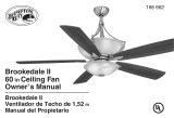
Blade balancing
The following procedure should
correct most fan wobble. Check
after each step.
Check that all blade and blade
bracket screws are secure.
Most fan wobble problems are
caused when blade levels are
unequal. Check this level by
selecting a point on the ceiling
above the tip of one of the blades.
Measure from a point on the center
of each blade to the point on the
ceiling. Measure this distance as
shown in figure. Rotate the fan
until the next blade is positioned
for measurement. Repeat for each
blade. Measurements deviation
should be within 3 mm (1/8 in.). Run
the fan for 10 minutes.
Use the enclosed Blade Balancing
Kit if the blade wobble is still
noticeable.

16
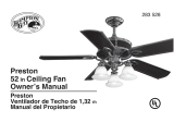
The balancing kit should only be used if there is an
unacceptable amount of fan wobble after completing
all the steps in the user manual under “Fan Blades
Assembly”.
1. Turn the fan on and set the speed control setting to a
speed at which the wobble is the greatest.
2. Turn off the fan and allow it to come to a complete
stop. Mark the blades with masking tape number
1-5. Select one blade and place the balance clip on it
halfway between the blade holder and the blade tip on
the trailing edge of the blade.
3. Turn the fan on. Note whether the wobble has
increased or decreased. Turn the fan off, move the clip
to another blade, and retest. Repeat this procedure
on all blades noting the blade on which the greatest
improvement is achieved.
4. Adjust the clip on this blade as shown in the
illustration and operate the fan to find the position
where the clip gives the greatest improvement.
5. Remove the clip, clean the area where the weight is
to be added, and install a balancing weight to the top of
the blade along the center line near the point where the
clip was positioned on the blade.
6. If the fan wobble problem has not been corrected,
you may wish to try to improve the balancing further by
using the balancing clip and additional weights.
Attach the plastic
clip on blade
weight balance
Blade Balancing Kit

17
Care of your fan
Troubleshooting
Here are some suggestions to help you maintain your fan.
1. Because of the fan’s natural movement, some
connections may become loose. Check the support
connections, brackets, and blade attachments twice a year.
Make sure they are secure. (It is not necessary to remove fan
from ceiling.)
2. Clean your fan periodically to help maintain its new
appearance over the years. Use only a soft brush or lint-free
cloth to avoid scratching the finish. The plating is sealed with
a lacquer to minimize discoloration or tarnishing. Do not
use water when cleaning. This could damage the motor, the
wood, or possibly cause an electrical shock.
3. You can apply a light coat of furniture polish to the wood
blades for additional protection and enhanced beauty. Cover
small scratches with a light application of shoe polish.
4. There is no need to oil your fan. The motor has
permanently lubricated sealed ball bearings.
-Check main and branch circuit fuses or breakers.
-Check line wire connections to the fan and switch wire connections in the
switch housing
-Make sure all motor housing screws are snug
-Make sure the screws that attach the fan blade bracket to the motor hub is tight
-Make sure wire nut connections are not rattling against each other or the interior wall of the
switch housing
-Allow a 24-hour “breaking-in” period. Most noises associated with a new fan disappear during
this time.
-If using a ceiling fan light kit, make sure the screws securing the glassware are tight. Check
that the light bulb is also secure.
-Make sure there is a short distance from the ceiling to the canopy. It should not touch the
ceiling.
-Make sure your ceiling box is secure and rubber isolator pads are used between mounting
bracket and outlet box.
PROBLEM SOLUTION
Fan will not start
Fan sounds noisy
WARNING: make sure the power
is off at the electrical panel box
before you attempt any repairs.
Refer to the section, “making
electrical connections”.
Contact a qualified electrician or call the Customer Care Service Team at 1-866-885-4649
Customer Service hours of operation are 9:00AM-5:00PM EST-Monday-Friday
is a trademark of General Electric Company
and is under license by Safety Quick Lighting & Fans Corp.
4400 North Point Parkway, Suite 154, Alpharetta, GA 30022

18
FCC caution
This device complies with part 15 of the FCC Rules. Operation
is subject to the following two conditions:
1. This device may not cause harmful interference
2, This device must accept any interference received,
including interference that may cause undesired operation.
NOTE: this equipment has been tested and found to comply with the
limits for a Class B digital device, pursuant to part 15 of the FCC rules.
These limits are designed to provide reasonable protection against
harmful interference in a residential installation. This equipment
generates, uses and can radiate radio frequency energy and, if not
installed and used in accordance with the instructions, may cause
harmful interference to radio communications. However, there is no
guarantee that interference will not occur in a particular installation. If
this equipment does cause harmful interference to radio or television
reception, which can be determined by turning the equipment off and on,
the user is encouraged to try to correct the interference by one or more
of the following measures:
• Reorient or relocate the receiving antenna.
• Increase the separation between the equipment and the receiver.
• Connect the equipment into an outlet on a circuit different from that to
which the receiver is connected.
• Consult the dealer or an experience radio / technician for help.
CAUTION: any changes or
modifications not expressly
approved by the party
responsible for compliance
could void the user’s authority
to operate the equipment
/