Page is loading ...

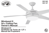
1.37 m (54 in.)
Morgan LED Lighted Ceiling Fan
MODELS: 20673 & 20680
120V 60Hz, MADE IN CHINA
User Manual
Customer Assistance
1-866-885-4649
re Service Team at 1-866-885-4649
re 9:00AM-5:00PM EST -Monday-Friday
Note: Installation videos for fans with GE Powerplug quick connection technology
on www.gelightingandfans.com
can be viewed and downloaded
r

Safety Rules
2
1. To reduce the risk of electric shock, ensure electricity has
been turned off at the circuit breaker or fuse box before
beginning of installation.
2. All wiring must be in accordance with the latest edition of
National Electrical Code “ANSI/NFPA 70” and local electrical
codes. Electrical installation should be performed by a
qualified licensed electrician.
4. CAUTION: To reduce the risk of personal injury, use only
the screws provided with the outlet box.
6.
The weight of the fan is 7.85 kg (17.31 lb.). The outlet box
and support structure must be securely mounted and
capable of reliably supporting a minimum of 15.9 kg (35 lb.).
Use only UL Listed outlet boxes marked “FOR FAN
SUPPORT.”
7.
To prevent personal injury and damage, ensure that the
hanging location allows the blades a clearance of 7 feet (2.13m)
from the floor and 30in. (76 cm) from any wall or obstruction.
This fan is suitable for room sizes up to 225 square feet
(20.9 square meters).
8. Avoid placing objects in the path of the blades.
9. To avoid personal injury or damage to the fan and other
items, be cautious when working around or cleaning the fan.
10.Do not use water or detergents when cleaning the fan or
fan blades. A dry dust cloth or lightly damped cloth will be
suitable for cleaning.
11. After making electrical connections, spliced conductors
should be turned upward and pushed carefully up into
the outlet box. The wires should be spread apart with
the grounded conductor and the equipment-grounding
conductor on one side of the outlet box and ungrounded
conductor on the other side of the outlet box.
12. All screws must be checked and re-tightened where
necessary during installation.
5. CAUTION: To avoid personal injury, the use of gloves may
be necessary while handling fan parts with sharp edges.
Vaulted ceiling
angle is not to
exceed 11 degrees.
blade edge
7 feet
(2.13m)
(76 cm)
30
inches
READ AND SAVE THESE INSTRUCTIONS
3. WARNING: to reduce the risk of electrical shock or fire, do
not use this fan with any solid-state fan speed control device.
It will permanently damage the electronic circuitry.
WARNING: To reduce the risk
of personal injury, do not bend
the blade arms (also referred
to as flanges), when installing
the brackets, balancing the
blades or cleaning the fan. Do
not insert foreign objects in-
between rotating fan blades.
WARNING: To reduce the risk of
fire, electric shock or personal
injury, mount to outlet box
marked “acceptable for fan
support of 15.9 kg (35 lb.) or
less” and use mounting screws
provided with the outlet box.
Most outlet boxes commonly
used for the support of light
fixtures are not acceptable for
fan support and may need to be
replaced. Due to the complexity
of the installation of this fan, a
qualified licensed electrician is
strongly recommended.
Note: This fan is UL damp rated
and suitable to use in locations
protected from weather.
Examples include roofed porches,
under canopies, marquees, and
interior locations subject to
moisture, such as basements,
barns, etc.

3
Basic Guidelines For Working With Electricity
1. Before working on a circuit, go to the main service panel
and remove the fuse or trip the breaker that controls that
circuit.
2. Tape a sign to the panel warning others to leave the circuit
alone while you work.
3. Before touching any wire, use a voltage tester to make
sure it’s not live.
4. Whenever you check for voltage in a receptacle, check
both outlets; each may be controlled by a separate wiring
circuit.
5. When replacing fuses, turn off the main power
rst. Make
sure your hands and feet are dry, and place one hand behind
your back to prevent electricity from making a complete
circuit through your chest. Touch a plug fuse only by its
insulated rim.
6. Remove cartridge fuses with fuse puller.
7. Use tools with insulated handles and ladders made of
wood or
berglass.
8. To protect children, place safety cover over any unused
outlets.
Shut off main
power at the
circuit breaker
or fuse panel
before removing
old
ture.
Remove
old
ture.
Disconnect wire.
MAIN
POWER

4
To Begin / Tools Needed (Not Supplied)
REQUIRED
Flathead
Screwdriver
Pliers
Step Ladder
Phillips Screwdriver
(4" recommended)
Wire Cutters
Wire Strippers
Safety Glasses
Electrical Tape
Soft Cloth

5
Hardware Included
Carefully unpack and identify each part to make sure you
have everything ready for installation. Lay out each part on
a clean flat area such as a table or floor. Check to make sure
you have the following:
AA 2
EE
4
CC
2
JJ
1
2
BB 2
II
1
LL
2
DD
9+1
replacement
KK
1
Hardware Bag Remote Control
PART DESCRIPTION
Wood Screw (Long)
Wire Connector
Transmitter
1.5 Volt AAA battery
Mounting Screw
(with lock washer)
Blade Screw
Wood Screw (Short)
Flat Washer
Balance Kit
Transmitter Holder
QUANTITY
FF
AA
DD
EE
LL
BB
II
KK
CC
JJ
+
-
FF
ATTENTION: Parts are not to scale.
NOTE: +1 = Extra quantity supplied
for future use if needed
GG
HH
HH
GG
Rubber Washer (4mm)
Rubber Washer (7mm)
2
2

6
Package Contents
Carefully unpack and identify each part to make sure you
have everything ready for installation. Lay out each part on
a clean flat area such as a table or floor. Check to make sure
you have the following:
A 1
E
1
1
1
M
4
C
G
K
B 1
F
D
1
H
L
3
PART DESCRIPTION
Powerplug receptacle
Coupling cover
Shade
Blade
Canopy mounting screw
Canopy assembly
Motor assembly
LED light kit
QUANTITY
Functional Fasteners
N
O
K
1
2
Collar set screw
Clevis pin
L
1
Cotter pin
M
3
Mounting plate screw
1
Canopy trim ring
I
P
N
O
LED light kit mounting
screw
(Preassembled to metal housing)
Metal Housing
1
3
(Preassembled to mounting
bracket)
(Preassembled to coupling of
motor assembly)
(Preassembled to coupling of
downrod assembly)
(Preassembled to coupling of
downrod assembly)
(Preassembled to mounting
plate of motor assembly)
P
ATTENTION: Parts are not to scale.
A
G
E
H
B
D
C
F
I
Wire extension
Keep this for longer downrod
(option sold separately) installation.
Instructions are available at
www.gelightingandfans.com)
1
J
J

7
Fan Installation Drawing
WARNING: Review important safety instructions before installation.
Outlet box (not provided)
Ground wire from housing
Black wire
J slot
Locking pin terminal
Mounting bracket push lever
Ground wire from mounting bracket
Wire connector
Ground wire from downrod assembly
Hanger ball
Canopy
Canopy trim ring
Downrod
Coupling cover
3-pin connector- male
3-pin connector-female
Clevis pin
Mounting plate screw
9-pin connector-male
Blade screw
Metal housing
LED light kit
9-pin connector-female
Shade
LED light kit mounting screw
Blade
Cotter pin
Collar set screw
Motor assembly
Neutral white wire
Powerplug receptacle
Flat washer
Outlet box screw
Plug locking pin
Canopy mounting screw
Mounting bracket
Black wire from receiver
White wire from receiver
Receiver
White wire from mounting bracket to fan
Blue wire from mounting bracket to fan
Black wire from mounting bracket to fan
Reverse switch
Wood screw
Rubber washer

Fan Installation
8
Fig 2
Fig 1
powerplug
receptacle
-
ground
(green/
bare)
wire
white
wire
black wire
black wire
G
W
L1
Fig 3
L1
ground
black
L1
W
G
white wire
green/bare
wire
whi
outlet box
L2
red
(CLOSE-UP VIEW of TERMINALS on Powerplug Receptacle)
white
green
black (live)
(L1)
(L2)
W
G-ground
WIRING DIAGRAM 2:
Typical Wiring Configuration for 2 Wall Switches
red (live 2)
WHITE
white
green
black(live 1)
(L1)
(L2)
W
G-ground
This Fan is supplied with a remote control receiver
and transmitter to operate the fan and light. The
L2 terminal is not activated on this fan. The red wire
can be capped off with a wire nut or inserted into L2.
Only 1 wall switch will be operational.
MAKING THE ELECTRICAL CONNECTIONS
t
e
Prepare wiring from outlet box. Be sure there are no
deep cuts in the exposed copper wiring as it could
break off in the terminals. Cut and strip 1/2 in. of
insulation from end of each wire if necessary. (Fig 1)
NOTE: Do NOT strip any more than 1/2 in. of insulation
from end of wires as this could cause a short at any
time.
IMPORTANT: Wiring must not come down and around
the face of powerplug receptacle.
Connect GREEN/BARE wire from ceiling to terminal in
powerplug receptacle marked G. Secure the wire by
tightening the small set screw.
Reference the wiring configuration diagrams below for
other wiring options into the terminal. L1 is the only
active live terminal on this fan.
WIRING DIAGRAM 1:
Typical Wiring Configuration for 1 Wall Switch
NOTE: If you do not have standard wiring configurations
and have questions about the wiring in your outlet box,
please contact a qualified electrician.
Electrical wiring (refer to Fig 2 and Fig 3 as necessary)
Connect BLACK wire from ceiling to terminal in
powerplug receptacle marked L1. Secure the wire by
tightening the small set screw.
Connect WHITE wire from ceiling to terminal in
powerplug receptacle marked W. Secure the wire by
tightening the small set screw.
can be made as follows:

Fan Installation
WIRING DIAGRAM 3:
Wiring Configuration with more than 1 of the same
the outlet box
white
green
black
(L1)
(L2)
W
G-ground
wire nut
white
When multiple wires are connected together, use a
solid wire 12-14 AWG jumper lead to insert into the
receptacle terminal.
WARNING: To avoid possible
electric shock, be sure electricity is
turned off at the main fuse box
before wiring.
NOTE: Fan must be installed at
a maximum distance of 6 m (20
ft.) from the transmitting unit for
proper signal transmission between
the transmitting unit and fan’s
receiving unit.
CAUTION : Do not use wall switch
with dimmer function.
WARNING : Do not use an existing
mounting bracket in the outlet box,
replace it with the powerplug
receptacle that is included with the
fan.
colored wires in
1.
Use metal outlet box (sold separately) suitable
for fan support. Secure outlet box directly to the
building structure using wood screws (AA). Outlet
box must support 15.9 kg (35 lb.) min.
DANGER: A loose outlet box can cause the
fan to wobble and increase the fan’s
potential to fall, which could result in
serious injury or death.
A
BB
CC
2.
Install powerplug receptacle (A) to outlet box
using the mounting screws (with lock washer)
(BB) and flat washers (CC) provided with the
outlet box. (Two additional mounting screws
(with lock washer) (BB) and flat washers (CC)
are provided in the hardware bag).
Rubber Washer
The placement of the powerplug
receptacle on the ceiling is important for the
fan plug to make the correct installation and
securement. The powerplug should be evenly
flush with the ceiling. Use the rubber washers
as shown in the figures on next page.
NOTE:
AA
INSTALLING THE POWERPLUG RECEPTACLE
View Installation Video@
www.gelightingandfans.com
NOTE: Be sure to push each wire from ceiling all the
way into corresponding terminal on powerplug
receptacle. If wire is not inserted completely, there is a
possibility that the electrical connection will fail. If you
have multiple wires connected together, add a jumper
lead and insert jumper lead into terminal. One single
wire is inserted into terminal.

Fan Installation
10
INSTALLING THE POWERPLUG RECEPTACLE WITH RUBBER WASHER
It is important for the powerplug receptacle to be flush with the ceiling surface. Outlet boxes are typically
not even with the surface or sheet rock and the rubber washers will help to reduce or eliminate the gap.
Follow these instructions.
Fig 1. Outlet box is flush with the ceiling or the
gap is less than 1.5mm, use 4mm rubber washer
provided. Place the washer above the powerplug
receptacle as shown.
Fig 3. Outlet box and the ceiling with gap from
3mm to 5mm, use both 4mm and 7mm rubber
washers provided. Place the washer above the
powerplug receptacle as shown.
4mmrubber w asher
0-1.5mm
1.5-3mm
7mm rubber washer
4mm rubber washer
>3mm
7mm rubber washer
Fig 2. Outlet box and ceiling with gap is more than
1.5mm but less than 3mm, use the 7mm rubber
washer provided. Place the washer above the
powerplug receptacle as shown.
Fig 1.
Fig 2.
Fig 3.

Fan Installation
2.
3.
4.
5.
M
6.
N
B
L
B
Plug locking
pin
Mounting bracket
push lever
HANGING THE FAN
Remove the rubber insert located on the canopy
mounting screws (K) on both sides before installation.
1.
K
rubber insert
A
Locking pin
terminal
N
B
Remove the cotter pin (N) and clevis pin (M) from the
downrod of the canopy assembly (B).
Note: For installation and use of longer downrod
(option sold separately), instructions are available at
www.gelightingandfans.com
Place the canopy trim ring (C) on top of motor assembly (E)
and coupling cover (D) onto the downrod of the canopy
assembly (B).
B
D
C
E
To install the fan, raise the assembled fan housing up to the
ceiling receptacle (A). Press up on the push lever while lifting
the fan canopy (B) up to the receptacle (A) fully inserting the
fan plug locking pin into the receptacle locking pin terminal.
For correct alignment, make sure the mounting bracket
push lever on the canopy is placed in the middle between
the receptacle j slots as shown in the picture. Keep the
lever pushed up while turning the fan to the right (clockwise)
as shown in step 7.
Loosen (but do not remove) the two collar set screws (L),
from the coupling on the top of the motor assembly (E).
Attach the 3-pin connectors from the downrod of the
canopy assembly (B) and motor assembly (E). Carefully
feed connectors into the downrod of the canopy
assembly (B).
3-pin connectors
L
B
E
WARNING: Failure to properly install cotter pin
could result in fan loosening and possibly falling.
Carefully insert the clevis pin (M) through the holes in the
collar and downrod (B). Be careful not to jam the clevis
pin (M) against the wiring inside the downrod (B).
Insert the cotter pin (N) through the hole near the end of
the clevis pin (M) until it snaps into its locked position.
Tighten two set screws (L) at top of the fan motor collar
firmly and evenly until fully engaged.
Align the holes at the bottom of the downrod (B) with the
holes in the collar on top of the fan motor assembly (E).
E
M
J slot

12
Fan Installation
Align the slotted hole on the canopy trim ring (C) with
the mounting bracket push lever, Take both hands
and push the canopy trim ring (C) up to the top of the
canopy (B). The canopy trim ring (C) will snap and lock
into place on the canopy (B) .
ATTACHING THE FAN BLADES
B
C
E
I
EE
Remove and discard the preassembled plastic motor blocks
but retain the screws(EE). Attach the blade (I ) to the motor
assembly (E), secure with three (3) blade screws (EE) each.
Repeat for the remaining blades, tighten all screws.
Tighten all the 4 canopy mounting screws (K).
K
Groove
Tab
K
7.
FINISHING THE FAN INSTALLATION
B
8.
10.
1.
2.
Make sure the tab on the mounting bracket socket
is properly seated in the groove in the hanger ball/
downrod assembly (B). This will help to balance the
ceiling fan.
WARNING: Failure to properly seat the tab in the
groove could cause damage to wiring.
Rotate the canopy to the right (clockwise), continue
turning the canopy until the screws (K) lock into
place on the receptacle j slots.
Note: You may need to loosen the canopy screws
slightly, if you find it's difficult to lock the screws
into the receptacle j slots.
9.

13
INSTALLING THE LIGHT KIT
1.
Remove 1 of the 3 mounting plate
screws (O) from the mounting plate
of motor assembly and loosen the
other 2.
Fan Installation
3.
Remove the 3 LED light kit mounting screws
(P) from the metal housing (F), and save for
later use.
O
G
P
F
4.
5.
Securely attach shade (H) by twisting
clockwise onto the metal housing (F).
Note: Before starting installation, disconnect the power by turning off the circuit breaker or removing the fuse at fuse box.
Turning power off using the fan switch is not sufficient to prevent electric shock.
F
9-pin connector
F
H
2.
Guide the 9-pin connector through
the center hole on the metal housing
(F). Raise the metal housing (F) up to
the mounting plate, position keyhole
slots around the mounting plate
screws (O) and twist clockwise.
Insert the mounting plate screw (O)
that you had previously removed.
Tighten all screws.
Attach the 9-pin connectors from the LED light kit (G) and
motor assembly. Tuck the connections neatly into the LED
light kit (G), align the 3 screw holes on LED light kit (G) to
the holes on metal housing (F). Insert the 3 LED light kit
mounting screws (P) that you had previously removed.
Tighten all screws.
Note: Both connectors are polarized and will only fit
together one way. Make sure the connectors are properly
aligned before connecting them. Incorrect connection
could cause improper operation and damage to the product.
F
P

Operation Instructions
+
-
+
-
AAA
AAA
REMOTE CONTROL OPERATIONS
Step 1. Restore power at circuit breaker and turn the wall switch to the on
position (if using wall switch) to test for proper operation,
Step 2. Open the battery compartment cover, and then install two 1.5-volt
AAA batteries (KK) provided in the remote control bag. Ensure the
batteries are installed correctly with regard to polarity (+ and -).
Step 3. Check “ O " and " I " dip switch: For this fan the dip switch should be
in the “I” position, allowing for dimming of the light. Place the switch in the
“0” position to turn the dimming feature off if you do not want the dimming
feature.
Step 4. Close the battery compartment cover and see below diagram for the
function of each button on the transmitter.
Step 5. Select a location to install the transmitter holder (JJ), Mount the
transmitter holder (JJ) using the wood screws (LL) provided.
"Sync" switch:
“ O " and " I " dip switch
This button turns the fan ON or OFF.
" " button
This button delays the light turning off
for approximately 5 seconds, enabling
you to exit your room before the light
turns completely off.
" " button
This button controls the light and also
controls the brightness setting. Press and
release the button to turn the light ON or OFF.
Press and hold the button to set the desired
brightness: the light will slowly illuminate to
maximum light output and then stop when
holding the button, then release the button
and hold it again until it reaches minimal
illumination where it will automatically stop
again. The light button has an auto-resume,
it will stay at the same brightness as the
last time it was turned off.
Low speed
Medium speed
High speed
Note :
.
To prevent damage to transmitter, remove the batteries if not used for long periods.
.
Replace batteries as a simultaneous set – always replace the whole set of batteries at one time, taking care not to mix old and new ones, or batteries of
different types.
.
Please contact your local batteries recycling center for proper battery disposal information.
Operation indicator
IMPORTANT: If the remote control is not operating correctly, please follow
the steps on page 16, item 5 for syncing the switch. Use the corner of the
battery cover to press the “Sync” switch for syncing function.
Note: This Fan and Remote has a dimming function for the light. You can
control the brightness of the light with the on the hand held
remote. Please see below for Remote Functions.
" " button
REMOTE FUNCTIONS

Operation Instructions
FAN REVERSE FUNCTION
The reversible motor provides upward and downrod air flow for desired air circulation to save energy, see below
for the details.
FCC ID: 2AAZPFAN61T3SP
This device complies with part 15 of the FCC Rules. Operation is subject to the following two conditions:
1. This device may not cause harmful interference, and
2.
this device must accept any interference received, including interference that may cause undesired operation.
CAUTION: Any changes or modifications not expressly approved by the party responsible for compliance could void the user’s authority
to operate the equipment.
Note: This equipment has been tested and found to comply with the limits for a Class B digital device, pursuant to part 15 of the FCC Rules.
These limits are designed to provide reasonable protection against harmful interference in a residential installation. This equipment generates,
uses and can radiate radio frequency energy and, if not installed and used in accordance with the instructions, may cause harmful interference
to radio communications. However, there is no guarantee that interference will not occur in a particular installation. If this equipment does cause
harmful interference to radio or television reception, which can be determined by turning the equipment off and on, the user is encouraged to try
to correct the interference by one or more of the following measures:
Reorient or relocate the receiving antenna.
rease the separation between the equipment and the receiver.
rcuit different from that to which the receiver is connected.
TV technician for help.
Warm weather - Switch to the “Forward”
position: A downward air flow creates a
cooling effect as shown. This allows you
to set your air conditioner on a higher
setting without affecting your comfort.
Cool weather - Switch to the “Reverse”
position: An upward air flow moves warm
air off the ceiling as shown.This allows you
to set your heating unit on a lower setting
without affecting your comfort.
The reverse switch is located on the light
kit housing, remove the shade to access
the switch. Slide reverse switch to change
fan rotation.
Note: wait for fan to stop before reversing
the direction of the blade rotation.

Remote Control Pairing Instructions
Important Note : By default, every fan has been pre-programmed at the factory and should be fully
functional once installation is completed. There is no need to perform the pairing process.
Make sure all wiring connections have been properly made and are secure.
Make sure batteries are installed correctly in the transmitter.
Make sure batteries have a full charge or replace with new batteries.
Make sure all switches of the power supply to the fan motor are turned on.
Should you find the fan or remote control not working or not fully functional after installation or
during use, pairing of the remote control can be done by following the below simple procedures.
Note, however, that there could be other reasons as to why a fan or a remote control is not working:
REMOTECONTROLPAIRINGINSTRUCTIONS
.
.
.
.
The remote is not functioning properly, and you want to reset a fan remote control, or
You are replacing the original transmitter or receiver, or
You have multiple ceiling fans of the same model in one location and you wish
to be able to control them with one remote.
These procedures apply if:
PROCEDURESFORPAIRINGRECEIVERANDTRANSMITTER
.
.
.
1. Turn OFF the power/isolation switch to ALL fans that you would like to program to the same
hand held remote.
2. Remove the battery cover to access the "Sync" switch on the hand held remote.
3. Install two 1.5 V AAA batteries and make sure the polarity of the batteries is correct.
4. Turn on the power/isolation switch to ALL fans.
5.
Press the "Sync" switch with the corner of the battery cover (you can also use a small screwdriver
or ballpoint pen) to change the frequency settings within 30 seconds after restoring the power.
The lights will flash (on/off) 3 times and remain bright, then the pairing process is complete.
6.
Try different speed settings on the transmitter to ensure all the fans are now fully functional. If not,
repeat the process starting from Step 1 again.
IF USINGONEREMOTECONTROLTOCONTROLMULTIPLEFANS
1. Turn OFF the power/isolation switch to the fan.
2. Remove the battery cover to access the "Sync" switch on the hand held remote.
3. Install two 1.5 V AAA batteries and make sure the polarity of the batteries is correct.
4. Turn on the power/isolation switch to the fan.
5.
Press the "Sync" switch with the corner of the battery cover (you can also use a small screwdriver
or ballpoint pen) to change the frequency settings within 30 seconds after restoring the power.
The light will flash (on/off) 3 times and remain bright, then the pairing process is complete.
6. Try different speed settings on the transmitter to ensure the fan is now fully functional. If not,
repeat the process starting from Step 1 again.
TORESETINDIVIDUALREMOTECONTROLFOREACHFAN/INSTALLINGANEWRECEIVER
Note: If you have more than one fan of the same model but wish to only perform the pairing on
one fan, follow the same steps starting from step 1 to step 6. Make sure to only power ON one
fan at a time, and power OFF all the nearby fans to avoid picking up the same signal.

Blade Balancing
The following procedure should
correct most fan wobble. Check
after each step.
Check that all blade and blade
bracket screws are secure.
Most fan wobble problems are
caused when blade levels are
unequal. Check this level by
selecting a point on the ceiling
above the tip of one of the blades.
Measure from a point on the center
of each blade to the point on the
ceiling. Measure this distance as
nafehtetatoR.erugifninwohs
until the next blade is positioned
for measurement. Repeat for each
blade. Measurements deviation
should be within 3 mm (1/8 in.). Run
the fan for 10 minutes.
17
Use the enclosed Blade Balancing
Kit if the blade wobble is still
noticeable.
Warning: Do not bend blades if the
measurement is off.

Blade Balancing Kit
The balancing kit should only be used if there is an
unacceptable amount of fan wobble after completing
all the steps in the user manual under “Attaching the
Fan Blades”.
1.
Turn the fan on and set the speed control setting to
the speed at which the wobble is the greatest.
2. Turn off the fan and allow it to come to a complete
stop. Mark the blades with masking tape number
1-3. Select one blade and place the balance clip on it
halfway between the blade holder and the blade tip on
the trailing edge of the blade (fig. a) .
3. Turn the fan on. Note whether the wobble has
increased or decreased. Turn the fan off, move the clip
to another blade, and retest. Repeat this procedure
on all blades noting the blade on which the greatest
improvement is achieved.
4. Adjust the clip on this blade as shown in the
noitisopehtdnifotnafehtetarepodnanoitartsulli
where the clip gives the greatest improvement
6. If the fan wobble problem has not been corrected,
you may wish to try to improve the balancing further by
using the balancing clip and additional weights.
5. Clean the area on top of the blade near where the clip
is located. Install a balancing weight to the top of the
blade along the center line (fig c).
(fig. b).
fig. a
attach the plastic
clip on blade
fig. b
fig. c
Weight
balance
18

User Servicing Instructions
PRODUCT MAINTENANCE
ARNING: Make sure the power is off
at the electrical panel box before
you attempt any repairs. Refer
to the section “Making Electrical
Connections“, page 8.
Here are some suggestions to help you maintain your fan.
Because of the fan’s natural movement, some connections
may become loose. Check the support connections, brackets,
and blade attachments twice a year. Make sure they are
secure. (It is not necessary to remove fan from ceiling.)
Clean your fan periodically to help maintain its new
appearance over the years. Use only a soft b
rush or lint-free
htiw delaes si gnitalp ehT .hsin if eht gnihctarcs diova ot htolc
a lacquer to minimize discoloration or tarnishing. Do not
use water when cleaning. This could damage the motor, the
wood, or possibly cause an electrical shock.
There is no need to oil your fan. The motor has permanently
lubricated sealed ball bearings.
TROUBLESHOOTING
is a trademark of General Electric Company
and is under license by
SQL Lighting and Fans, LLC
4400 North Point Parkway, Suite 154, Alpharetta, GA 30022
V1.2016
-Make sure all motor housing screws are snug.
-Make sure the screws that attach the fan blade brack
et to the motor hub is tight.
-Make sure wire nut connections are not rattling against each other on the interior wall
of the switch housing.
-Allow a 24-hour “breaking-in” period. Most noises associated with a new fan
disappear during this time.
-Make sure there is a short distance from the ceiling to the canopy. It should not touch
the ceiling.
-Make sure your ceiling box is secure.
PROBLEM SOLUTION
Fan will not start
Fan sounds noisy
The LED will not light
-Ensure batteries are new and installed correctly.
-Pair the remote control by following the pairing procedure on page 16 item 5.
Remote control
-Ensure the pin connector is attached/inserted correctly.
-Ensure the power supply is turned on.
-Ensure the circuit breaker is set to “ON” position.
Note: Installation videos for fans with GE Powerplug quick connection
technology can be viewed and download on www.gelightingandfans.com
-Check main and branch circuit fuses or breakers.
-Check to make sure the wall switch is in the on position.
-Check to make sure the wiring to the powerplug receptacle is correctly done with the
live wire inserted and secured into the powerplug receptacle terminal.

Comuníquese con un electricista cali cado o llame al Servicio de Atención al cliente al 1-866-885-4649
El horario del Servicio de Atención al cliente es de 9:00 a. m. a 5:00 p. m. EST, de Lunes a Viernes.
fi
Nota: Videos de Instalación para ventiladores con la tecnología de
instalación rápida con enchufe GE pueden ser vistos y descargados en
www.gelightingandfans.com
Manual del Usuario
1,37 m (54 pulgadas)
Ventilador de techo LED Morgan
MODELOS
:
20673 & 20680
120V 60Hz, HECHO EN CHINA
Asistencia al cliente
1-866-885-4649
/