Page is loading ...

READ and SAVE THIS
INSTRUCTION MANUAL
MAR 2003
Snap-On Tools Corporation
1-800-268-7959
2-POST
MODEL # EELR326A
INSTALLATION AND OPERATION
MANUAL
6-1640

TABLE OF CONTENTS
PAGE
1 SAFETY AND OPERATING INSTRUCTIONS............................................................................2
2 SPECIFICATIONS ...........................................................................................................................3
3 CONTENTS .......................................................................................................................................4
4 INSTALLATION REQUIREMENTS.............................................................................................5
5 INSTALLATION INSTRUCTIONS ...............................................................................................6
5.1 UNPACKING PROCEDURE ........................................................................................................6
5.2 BAY LAYOUT...............................................................................................................................7
5.3 SAFETY SHUT-OFF BAR INSTALLATION ..............................................................................8
5.4 SAFETY SHUT-OFF BAR ADJUSTMENT.................................................................................8
5.5 TOWER POSITIONING AND SETUP .......................................................................................10
5.6 ARM INSTALLATION ...............................................................................................................10
5.7 POWER PACK INSTALLATION...............................................................................................11
5.8 HYDRAULIC SYSTEM INSTALLATION ................................................................................12
5.9 SAFETY RELEASE CABLE ROUTING AND ADJUSTMENT ...............................................14
5.10 HYDRAULIC SYSTEM BLEEDING AND LEVELING PROCEDURE..............................16
5.11 HYDRAULIC ADJUSTMENT PROCEDURE.......................................................................17
5.12 TOWER POSITIONING AND ANCHORING.......................................................................17
5.13 SHIMMING OF THE REMAINING TOWER .......................................................................19
5.14 ARM RESTRAINT ADJUSTMENT.......................................................................................20
6 LIFT MAINTENANCE GUIDELINES.........................................................................................20
6.1 SAFETY INSTRUCTIONS..........................................................................................................20
6.2 PERIODIC MAINTENANCE......................................................................................................20
7 SAFETY AWARENESS - AUTOMOTIVE LIFT INSTITUTE (ALI) ......................................22
8 PARTS MANUAL ...........................................................................................................................23
8.1 LIFT ASSEMBLY........................................................................................................................23
8.2 LIFT ASSEMBLY PARTS LIST.................................................................................................24
8.3 HYDRAULIC SYSTEM ..............................................................................................................26
8.4 HYDRAULIC SYSTEM PARTS LIST........................................................................................27
8.5 HYDRAULIC SYSTEM PARTS LIST........................................................................................28
8.6 POWER PACK: #6-2055 (AB-1381) 208-230V/1PH/60H
Z........................................................28
8.7 POWER PACK PARTS LIST: #6-2055 (AB-1381) 208-230V/1PH/60H
Z.................................29

2
1 SAFETY AND OPERATING INSTRUCTIONS
1. When using this lift, basic safety precautions should always be followed,
including the following.
2. Read all instructions in this manual and on the lift.
3. Inspect lift daily. Do not operate if it malfunctions or problems have been
encountered.
4. Never attempt to overload the lift. The manufacturer’s rated capacity is shown on
the identification label on the power side column. Do not override the operating
controls or the warranty will be void.
5. Before driving vehicle between the towers, position the arms to the drive-through
position to ensure unobstructed clearance. Do not hit or run over arms as this
could damage the lift and/or vehicle.
6. Only trained and authorized personnel should operate the lift. Do not allow
customers or bystanders to operate the lift or be in the lift area.
7. Position the lift support pads to contact the vehicle manufacturers recommended
lifting points. Raise the lift until the pads contact the vehicle. Check pads for
secure contact with the vehicle. Check all arm restraints and insure they are
properly engaged. Raise the lift to the desired working height.
8. Some pickup trucks may require an optional truck adapter to clear running boards
or other accessories.
NOTE: Always use all 4 arms to raise and support vehicle.
9. Caution! Never work under the lift unless the mechanical safety locks are
engaged.
10. Note that the removal or installation of some vehicle parts may cause a critical
load shift in the center of gravity and may cause the vehicle to become unstable.
Refer to the vehicle manufacturer’s service manual for recommended procedures.
11. Always keep the lift area free of obstruction and debris. Grease and oil spills
should always be cleaned up immediately.
12. Never raise vehicle with passengers inside.
13. Before lowering check area for any obstructions.
14. Before removing the vehicle from the lift area, position the arms to the drive-
through position to prevent damage to the lift and /or vehicle.

3
2 SPECIFICATIONS
Capacity: 9000 lbs. 4090 kg
Overall Width: 134” 3404mm
Width Between Columns: 107” 2717mm
Drive-Thru Width: 86 ½” 2197mm
Overall Height: 144” 3658mm
Under Bar Clearance: 140” 3556mm
Height to Lowered Lift Pads: 4” 102mm
Height to Raised Low Lift Pad: 5 ¾” 146mm
Height to Raised High Lift Pad: 8 ¾” 222mm
Front Arm Retracted Length: 23 ¼” 591mm
Front Arm Extended Length: 36 ¾” 933mm
Rear Arm Retracted Length: 35 ¾” 908mm
Rear Arm Extended Length: 57 ¼” 1454mm
Maximum Lifting Height: 77 ¼” 1962mm
Lift Time: 45 seconds
Power Requirements (Standard): 230 Volts AC, 1 Ph., 60Hz.
Figure 1 – Front View Figure 2 – Top View

4
3 CONTENTS
The complete lift is contained in two (2) packages:
1. The main structural components are packed in a steel frame.
2. The remaining parts are packed in an accessory box.
Main Structural Components includes:
1pc. - Power side tower and carriage assembly
1pc. - Slave side tower and carriage assembly
1pc. - Crossmember
1pc. - Hydraulic line for crossmember
Accessory box contents:
2pcs. - Front arms (Short) w/arm pins
2pcs. - Rear arms (Long) w/arm pins
2pcs. - Safety Covers w/Decals
1pc. - Power Pack
1pc. - Safety release cable assembly
1pc. - Valve Block (C/W Fittings)
1pc. - Safety shut-off microswitch assembly
1pc. - Hardware package w/Packing List
1pc. - Owner’s manual
1pc. - ALI manual “Lifting It Right”
1pc. - Automotive Lift Safety Tips
1pc. - Automotive Lift, Operation, Inspection and Maintenance manual
1pc. - “ALI” Quick Reference Guide

5
4 INSTALLATION REQUIREMENTS
IMPORTANT: It is the user’s responsibility to provide a satisfactory installation
area for the lift. Lifts should only be installed on level concrete floors with a
minimum thickness of five (5) inches or 130 mm. Concrete must have a minimum
strength of 4000 psi or 30 MPa and should be aged thirty (30) days prior to
installation. Please consult the architect, contractor or engineer if doubt exists as to
the strength and feasibility of the floor to enable proper lift installation and
operation.
It is the user’s responsibility to provide all wiring for electrical hook-up prior to
installation and to insure that the electrical installation conforms to local building
codes. Where required, it is the user’s responsibility to provide an electrical
isolation switch located in close proximity to the lift that will enable emergency stop
capability and isolate electrical power from the lift for any servicing requirements.
Tools Required:
a. 16ft. Measuring Tape
b. Chalk Line
c. Rotary Hammer Drill
d. 3/4” diameter Masonry Drill Bit
e. Hammer
f. SAE Wrenches and Ratchet Set
g. 2ft. Level
h. 4ft. Level
I. Crow Bar
j. One 12ft. Step Ladder
k. Side Cutters
l. Screwdrivers
m. 15 ft. Bleeder Hose (Clear) w/ 3/8”JIC Swivel F fitting on one end
n. 4” x 4” Wooden Blocks (for unpackaging)

6
5 INSTALLATION INSTRUCTIONS
When the lift arrives on site, please read the owner’s manual and check for any freight
damages. Also, check the contents to make sure no parts are missing before starting
installation. Gather all the tools listed and make sure the installation instructions are
fully understood before commencing installation.
5.1 UNPACKING PROCEDURE
1. Important! Place the main structural components on wooden blocks so that
the steel frames can be removed.
2. Remove plastic wrapping.
3. Remove crossmember, hydraulic line, and extensions.
4. Remove steel frames.
5. Lay towers on floor with the carriage side up.
6. Check the installation area for obstructions. (Lights, Heating Ducts, Ceiling,
Floor Drains...etc.)
7. Prepare the bay by selecting the location of the lift relative to the walls. Clear
area of all packaging materials to avoid trip hazards. Draw a chalk line on the
floor to represent the center line of the bay and a second chalk line crossing at 90°
for locating the lift towers. Refer to Figure 3.

7
5.2 BAY LAYOUT
Figure 3 – Bay Layout

8
5.3 SAFETY SHUT-OFF BAR INSTALLATION
Note: The safety shut off will disconnect the power to the power pack when an
obstruction touches the padded bar or the carriages reach their maximum
extension. The safety shut off switch is factory pre-wired. Refer to Figure 4 and 5.
Note: This procedure can be done on the floor.
1. Attach the Actuator Mounting Bracket (1-1378) to the crossmember using hex head
bolt 1/4” NC x 3/4” lg. bolt (6-0178), lockwasher 1/4” dia. (6-0056), and hex nut 1/4”
NC (6-0032).
2. Attach Actuator Bar assembly to the Actuator Mounting Bracket assembly using hex
head bolt 1/4” NC x 1 1/2” lg. (6-0027), lockwasher (6-0178), and hex nut 1/4” NC
(6-0032).
3. Slide Safety Shut-Off Microswitch Assembly over open end of actuator bar and bolt
the assembly to the crossmember using hex head bolt 1/4” NC x 3/4” lg. (6-0178),
lockwasher (6-0178), and hex nut 1/4” NC (6-0032).
4. Bolt Actuator Extension (1-1379) onto open end of actuator bar using (2x) hex head bolt
1/4” NC x 1 1/4” lg. (6-0027), lockwasher (6-0178), and hex nut 1/4” NC (6-0032).
5.4 SAFETY SHUT-OFF BAR ADJUSTMENT
Note: This procedure must be done last.
1. When the lift is fully installed, leveled. and operational, extend the carriages to their
full upper limit.
2. Lower the carriages about 1/4” to 1/2”.
3. Adjust the stopper bolt by threading the upper nut towards the head, and the lower nut
towards the bottom.
4. The bottom of the bolt should be touching the top of the carriage.
5. Tighten both stopper nuts onto the actuator bar extension.

9
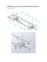
Figure 4 – Safety Shut-Off Bar Installation
Figure 5 – Safety Shut-Off Bar (Power Side)

10
5.5 TOWER POSITIONING AND SETUP
1. Locate the power side and slave side tower to the relative position as shown on
Figure 3. Double check all dimensions.
2. Using a step ladder, install the crossmember. Raise and place the crossmember
mounting hooks over the top of the tower. Install and tighten the crossmember
using four (4) 1/2”-13UNC x 1½”LG. hex head bolts, flat washers, lock washers
and hex nuts.
3. Check the towers to make sure they are located, and positioned in the correct
location. Refer to Figure 3.
5.6 ARM INSTALLATION
1. Remove (4) 5/16”-18UNC x 3/4”LG. hex head bolts that are locking the arm pins
to the arm. Install arms to carriages. Install so that the shorter arms (with the 30°
bend) are on the front, and the long arms on the rear. Refer to Figure 6.
2. Grease and insert arm pins. Align notch on arm pins to the tapped hole on the
arm. Using the 5/16” hex head bolts removed in previous step, reinstall and
tighten securely.
NOTE: Arm restraint device to be installed in Section 5.14.
Figure 6 – Arm Installation

11
5.7 POWER PACK INSTALLATION
1. Remove the red plastic cap located at the rear of the power pack, and install the
90° fitting (page 25, item 18) located in the hardware kit.
2. Bolt power pack to the mounting bracket on the power side tower using four (4)
5/16”-18UNC x 1”LG. hex head bolts, lock washers, flat washers and nuts.
Do not tighten.
3. A certified electrician must connect the 230Volt/Single phase power to the motor.
The electrical diagram is provided, refer to Figure 8.
Figure 7 – Powerpack Details

12
T
4
UP CONTROL MICROSWITCH
BUTTON SHUT-OFF
(NORMALLY OPEN) (NORMALLY CLOSED
DURING OPERATION)
M
T
1
230 VOLTS AC
SINGLE PHASE
POWER SUPPLY
Figure 8 – Electrical Diagram
5.8 HYDRAULIC SYSTEM INSTALLATION
Refer to Figure 9 and 10, and the Hydraulic System Parts List on page 26
Note: Save hydraulic caps and plugs for future use.
1. Do not tighten any hydraulic fittings until all connections have been made.
2. Remove plug from item 17. Install item 17 (page 26) to the 90° fitting on the
power pack (item 18).
3. Install the valve block to the power side tower using items 23 & 5.
4. On the power side cylinder, remove the cap off item 28 at the bottom rear and
install item 27.
5. Attach item 27 to item 53 on valve block.
6. At the bottom of the power side cylinder, remove the 1/4” cap from item 25 and
attach it to item 51 on valve block.
7. Attach the other end of item 17 to the 90° fitting (item 18) on the valve block.
8. Remove the two caps on item 39 and place it in the crossmember. Connect the slave
side end of this line to a bulkhead fitting (item 1) attached to the hydraulic line
(item 6).

13
9. Connect the power side end to the bulkhead fitting (item 1) attached to the
hydraulic line (item 30).
10. TIGHTEN ALL HYDRAULIC CONNECTIONS.
Caution: Over tightening could cause the flare seal to break.
11. Remove filler cap from power pack, and fill reservoir with 3.5 Gal. (13.2 L) of
ISO32 hydraulic oil (10 weight hydraulic oil). Remove breather screw when
filling and replace when full. Refer to Figure 7.
HYDRAULIC TUBE ASSEMBLY
PART #2-1140
VALVE BLOCK
PART #6-1362
ADAPTER,
¼" NPT M - 3/8" JIC M
PART #6-0276
ADAPTER,
¼" NPT M - ¼" JIC
PART #6-0281
90° ELBOW
PART #6-0804
TO POWER PACK
¼" HOSE
3/8" LINE
CLOSE
OPEN
Figure 9 – Hydraulic System Connections
Figure 10 – Hydraulic System Schematic

14
5.9 SAFETY RELEASE CABLE ROUTING AND ADJUSTMENT
The mechanical safety automatically engages. To release the mechanical safety, you
must first raise the lift approximately 2”, then pull the safety release lever down.
This disengages the power side safety dog and activates the safety cable to release
the slave side safety dog.
1. Install the safety release bracket on each tower as shown in Figure 10. Attach the
safety pulley to the bracket using the 3/8” x 5/8” LG. shoulder bolt, 5/16”
lockwasher and 5/16” hex nut. Attach the pulley bracket, complete with pulley, to
the tower using the 5/16” x 3/4” LG. hex bolt, 5/16” flat washer, 5/16” lockwasher,
and 5/16” hex nut.
Figure 11 - Safety Release Pulley Installation
2. Refer to Figure 12 for safety release cable routing. The end of the cable that has a
collar attaches to the slave side safety dog. The free end is fixed to the power side
safety dog using two (2) wire rope clips.
3. Install the safety release handle onto the power side safety dog.
4. Start routing the safety release cable from the slave side of crossmember. Feed
the cable over the small pulley, then guide the cable down along the inside of the
slave side tower. Pull the cable out through the opening in the back of the tower
near the safety dog.

15
5. Guide the cable up under the large pulley towards the end of the safety dog.
Remove the 3/8” x 1 ½” shoulder bolt from the safety dog. Feed the shoulder bolt
through the collar of the safety release cable and then replace the shoulder bolt
securely to the safety dog. NOTE: Make sure shoulder bolt, 3/8” dia. x 1 ½” lg.
(6-0801), is lock tight to safety dog.
6. Repeat step 2 for the power side tower.
7. Guide the cable up under the large pulley and then over the small pulley towards
the safety dog. Wrap the cable around the thimble (attached to the safety dog with
a 3/8” x 1 1/2” lg. shoulder bolt) and then clamp it using two (2) wire rope clips.
Do not tighten fully at this stage.
8. Adjust the cable length so that both safety dogs travel from full engagement position
to full release position when the safety release handle is pulled. Tighten both wire
rope clips firmly when adjustment is completed.
Figure 12 – Safety Release Cable Routing and Adjustment

16
5.10 HYDRAULIC SYSTEM BLEEDING AND LEVELING PROCEDURE
1. Ensure that both carriages are fully lowered.
2. Remove the bleeder cap from the “T” fitting at the bottom of the slave side cylinder.
3. Attach a 15ft. clear bleeding hose to the same fitting, and place the open end of the
hose into the power pack’s reservoir’s filler neck or in a container in which the oil
came in for reuse. Hose should be secured during the bleeding procedure.
4. Close the by-pass valve, and power up until the power side carriage reaches the
carriage stops.
5. Open the by-pass valve, and power up until oil is seen flowing out of the bleeder hose.
(No Air Bubbles). Bleed at least 1 gal. of hydraulic fluid through the system.
6. Remove the bleeding hose and reinstall the bleeder cap. Replace breather/filler cap.
7. Power up until slave side carriage reaches the carriage stops.
8. Close the by-pass valve and lower lift (both sides) until both carriages are fully
collapsed. Power up and lower (14”) lift a few times. When lift is fully down, open
the by-pass valve and raise the slave side 2-3” higher than the power side. Close the
by-pass valve.
9. Power up, and lower lift onto the first safety, on the power side. Open the by-pass
valve and lower slave side onto the same first safety. Close the by-pass valve. Lift is
now synchronized hydraulically.
10. Both power and slave sides must be completely down.
11. Check and add hydraulic fluid to power pack before cycling lift.
12. Install safety covers, and safety release lever knob. Securely.
13. After anchoring, set up a vehicle on the lift to make sure hydraulics are operating
properly.

17
5.11 HYDRAULIC ADJUSTMENT PROCEDURE
Important! Should your lift come out of synchronization, i.e. one carriage is higher than
the other, it is necessary to level the lift hydraulically.
When slave side is higher than the power side:
1. Lower lift on to the first safety on the power side.
2. Open by-pass valve. Push the down control lever. This will cause the slave side
carriage to be lowered. Stop lowering when the slave side carriage stops on the first
safety.
When power side is higher than the slave side:
1. Open the by-pass valve, raise lift until the slave side carriage is approximately 1-2”
higher than the power side carriage. Stop raising and close by-pass valve.
2. Lower lift by pushing the down control lever. Stop lowering when the power side
carriage touches the first safety.
3. Next, open the by-pass valve. Push the down control lever so that the slave side
carriage lowers. Stop lowering when the slave side carriage touches the first safety.
Close the by-pass valve.
5.12 TOWER POSITIONING AND ANCHORING
WARNING!
Failure to follow these instructions may cause an unsafe operating
condition.
WARNING!
Before proceeding with installation, review Section 4: Installation
Requirements & Tools.
1. Using a 4ft. level on top of the crossmember, determine which column is higher
(Figure 13).
2. Using 2 ft. level on the sides of the high column, ensure that the column is level in
the vertical position (Figure 14). Use shims under the column baseplate to hold
the column level. Ensure that the base plate is completely supported by shims
where it does not contact the floor (Figure 15).
WARNING! Do not use more than ½” (13mm) of shims. Anchor bolts supplied
allow for a maximum of ½” (13mm) of shim. If more than ½” (13mm)
of shims are required, DO NOT
proceed with installation and contact
Product Manufacturer / Supplier for further details.

18
Figure 13 – Crossmember Leveling Figure 14 – Tower Leveling
Figure 15 – Shim Placement
Figure 16 – Anchor Installation
3. Refer to Bay Layout (Figure 3) to ensure that the column is still in the proper
position. Using a rotary hammer drill with a ¾” masonry drill bit, drill holes in
the floor on the high side column using the tower baseplate as a template. Make
sure that the ¾” masonry drill is in good condition (Figure 16A).
4. Carefully clean out drilling dust from the anchor holes. Hammer in the anchor
bolts (Figure 16B). Hand tighten all anchor bolts.

19
5. Reconfirm that the column is level front to rear and side to side (Figure 14). Add
or remove shims as required.
6. Torque all anchor bolts to 150 ft-lbs. (203 Nm), continually checking that the
column is level as you proceed. If anchor bolts do not tighten to 150 ft-lbs. OR
project more than 1 ¾” above the concrete surface (Figure 16C), the concrete
MUST be replaced by an appropriate concrete pad. (Consult Product
Manufacturer / Supplier for further details).
5.13 SHIMMING OF THE REMAINING TOWER
1. Using a 4ft. level on the crossmember (Figure 14) and a 2ft. level on the low side
column (Figure 14), shim underneath the baseplate until the crossmember and
column are level. Ensure that the baseplate is completely supported by shims
where it does not contact the floor (Figure 15).
WARNING! Do not use more than ½” (13mm) of shims. Anchor bolts supplied
allow for a maximum of ½” (13mm) of shim. If more than ½” (13mm) of
shims are required, DO NOT proceed with installation. Contact Product
Manufacturer / Supplier for further details.
2. Refer to Bay Layout (Figure 3) to ensure that the column is still in the proper
position. Using a rotary hammer drill with a 3/4” masonry drill bit, drill holes in
the floor on the low side column using the column baseplate as a template. Make
sure that the 3/4” masonry drill is in good condition (Figure 16A).
3. Carefully clean out drilling dust from the anchor holes. Hammer in the anchor
bolts (Figure 16B). Hand tighten all anchor bolts.
4. Reconfirm that the crossmember is level (Figure 13) and that the column is level
front to rear and side to side (Figure 14). Add or remove shims as required.
5. Torque all anchor bolts to 150 ft-lbs. (203 Nm), continually checking that the
crossmember and column are level as you proceed. If anchor bolts do not tighten
to 150 ft-lbs. OR
project more than 1 ¾” above the concrete surface (Figure
16C), the concrete MUST be replaced by an appropriate concrete pad. (Consult
Product Manufacturer / Supplier for further details).
6. Verify that the entire lift is level both horizontally and vertically, to ensure
optimum lifting performance.
*Perform a monthly
inspection and torque all anchor bolts to 150 ft-lbs. (203 Nm).
/