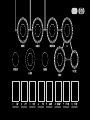
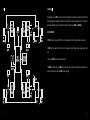
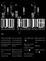
OTO Biscuit is a stereo effects processor that uses a combination of 8-bit digital and analog processing.
Capable of bitcrushing, sample-rate reduction ranging from 250Hz to 30kHz, and the ability to mute or invert any of the 8 bits, the Biscuit can create a wide range of effects from subtle bit reduction to glitchy digital noise. The analog multimode filter adds warmth and character, and the four built-in effects (waveshaper, delay, pitch shifter, and step filter) provide even more creative possibilities.
Biscuit is also MIDI compatible, allowing you to control its parameters remotely.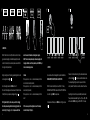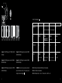


-
 1
1
-
 2
2
-
 3
3
-
 4
4
-
 5
5
-
 6
6
-
 7
7
-
 8
8
-
 9
9
-
 10
10
-
 11
11
-
 12
12
-
 13
13
-
 14
14
-
 15
15
-
 16
16
-
 17
17
-
 18
18
-
 19
19
-
 20
20
-
 21
21


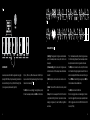
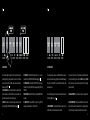
OTO Biscuit is a stereo effects processor that uses a combination of 8-bit digital and analog processing.
Capable of bitcrushing, sample-rate reduction ranging from 250Hz to 30kHz, and the ability to mute or invert any of the 8 bits, the Biscuit can create a wide range of effects from subtle bit reduction to glitchy digital noise. The analog multimode filter adds warmth and character, and the four built-in effects (waveshaper, delay, pitch shifter, and step filter) provide even more creative possibilities.
Biscuit is also MIDI compatible, allowing you to control its parameters remotely.
Ask a question and I''ll find the answer in the document
Finding information in a document is now easier with AI
Other documents
-
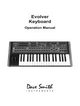 Dave Smith Instruments Evolver User manual
-
Sequential Mopho SE User manual
-
Moog Subsequent 37 CV User manual
-
Moog Sub 37 User manual
-
Moog Subsequent 37 User manual
-
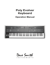 Dave Smith Instruments Poly Evolver Keyboard User manual
-
Dave Smith Instruments Evolver User manual
-
-
-

