Page is loading ...

IoT Controller
UC300
User Guide

2
Safety Precautions
Milesight will not shoulder responsibility for any loss or damage resulting from not following the
instructions of this operating guide.
The device must not be remodeled in any way.
Do not place the device close to objects with naked flames.
Do not place the device where the temperature is below/above the operating range.
Power off the device when installing or wirings.
Make sure electronic components do not drop out of the enclosure while opening.
The device must never be subjected to shocks or impacts.
Declaration of Conformity
UC300 is in conformity with the essential requirements and other relevant provisions of the CE,
FCC, and RoHS.
FCC Statement:
Any Changes or modifications not expressly approved by the party responsible for compliance
could void the user’s authority to operate the equipment.
This device complies with part 15 of the FCC Rules. Operation is subject to the following two
conditions:
(1) This device may not cause harmful interference, and
(2) This device must accept any interference received, including interference that may cause
undesired operation.
Note: This equipment has been tested and found to comply with the limits for a Class B digital
device, pursuant to part 15 of the FCC Rules. These limits are designed to provide reasonable
protection against harmful interference in a residential installation. This equipment generates,
uses and can radiate radio frequency energy and, if not installed and used in accordance with
the instructions, may cause harmful interference to radio communications. However, there is no
guarantee that interference will not occur in a particular installation. If this equipment does
cause harmful interference to radio or television reception, which can be determined by turning
the equipment off and on, the user is encouraged to try to correct the interference by one or
more of the following measures:
—Reorient or relocate the receiving antenna.
—Increase the separation between the equipment and receiver.
—Connect the equipment into an outlet on a circuit different from that to which the receiver is

3
connected.
—Consult the dealer or an experienced radio/TV technician for help.
FCC Radiation Exposure Statement:
This equipment complies with FCC radiation exposure limits set forth for an uncontrolled
environment. This equipment should be installed and operated with minimum distance 20cm
between the radiator& your body. This transmitter must not be co-located or operating in
conjunction with any other antenna or transmitter.
Copyright © 2011-2022 Milesight. All rights reserved.
All information in this guide is protected by copyright law. Whereby, no organization or individual
shall copy or reproduce the whole or part of this user guide by any means without written
authorization from Xiamen Milesight IoT Co., Ltd.
For assistance, please contact
Milesight technical support:
Email: iot.support@milesight.com
Tel: 86-592-5085280
Fax: 86-592-5023065
Address: Building C09, Software Park III,
Xiamen 361024, China
Revision History
Date Doc Version Description
Mar. 17, 2022 V 1.0 Initial version

4
Contents
1. Product Introduction ................................................................................................................................ 5
1.1 Overview ...........................................................................................................................................5
1.2 Features ........................................................................................................................................... 5
2. Hardware Introduction ............................................................................................................................. 5
2.1 Packing List ..................................................................................................................................... 5
2.2 Hardware Overview ........................................................................................................................ 6
2.3 Application Wiring .......................................................................................................................... 6
2.4 LED Indicators ................................................................................................................................. 7
2.5 Reset Button .................................................................................................................................... 8
2.6 Dimensions (mm)........................................................................................................................... 8
3. Hardware Installation ............................................................................................................................... 8
3.1 Antenna Installation ....................................................................................................................... 8
3.2 Device Installation ........................................................................................................................ 10
3.2.1 Wall Mounting ....................................................................................................................10
3.2.2 DIN Rail Mounting ............................................................................................................. 11
4. Operation Guide ...................................................................................................................................... 11
4.1 Log in the ToolBox ....................................................................................................................... 11
4.2 LoRaWAN Settings ....................................................................................................................... 13
4.3 Data Interface Settings ................................................................................................................16
4.3.1 Basic Settings .................................................................................................................... 16
4.3.2 Digital Input/Pulse Settings.............................................................................................16
4.3.3 Digital Output Settings ..................................................................................................... 17
4.3.4 RS485 Settings .................................................................................................................. 18
4.3.5 RS232 Settings .................................................................................................................. 20
4.3.6 Analog/PT100 Settings ....................................................................................................21
4.4 IF-THEN Command ...................................................................................................................... 22
4.5 Milesight D2D Settings ................................................................................................................ 24
4.6 Maintenance ..................................................................................................................................27
4.6.1 Upgrade .............................................................................................................................. 27
4.6.2 Backup ................................................................................................................................ 28
4.6.3 Reset to Factory Default .................................................................................................. 28
5. Device Payload ........................................................................................................................................ 29

5
1. Product Introduction
1.1 Overview
UC300 is an IoT controller used for remote control and data acquisition from multiple sensors. It
contains different I/O interfaces such as analog inputs, digital inputs, relay outputs, serial ports
and so on, which support remote device data transmission and control via LoRaWAN®. Besides,
UC300 supports multiple trigger conditions and actions which works autonomously even when
the network drops.
1.2 Features
Easy to connect with diverse wired sensors through DI/DO/AI/PT100/RS232/RS485
interfaces
Support LoRaWAN®wireless communication
Multiple triggering conditions and actions
Embedded watchdog for work stability
Industrial metal case design with wide operating temperature range
Compliant with standard LoRaWAN®gateways and network servers
Quick and easy management with Milesight IoT Cloud solution
2. Hardware Introduction
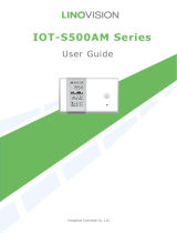
2.1 Packing List
1 × DIN Rail
Mounting Clip
4 × Wall Mounting
Kits
4 × Fixing Screws
1 × UC300 Device 1 × LoRaWAN®
Antenna
1 ×
Power Adapter
5 × Terminal Blocks

6
1 ×
Quick Start Guide
1 × Warranty
Card
If any of the above items is missing or damaged, please contact your sales representative.
2.2 Hardware Overview
2.3 Application Wiring

7
RS485 Terminal Resistor:
DIP Switch Description
1 on 2 off 3 off Add 120 Ω resistor between A and B
1 off 2 on 3 off Add pull-down resistor on B
1 off 2 off 3 on Add pull-up resistor on A
2.4 LED Indicators
LED Indication Status Description
SYS System Status
Static On System works
Slowly Blinks Fail to acquire data from data interfaces
Static On System error
ACT Network Status
Off Not join/register to network
Blinks as Requests Send join network requests
Blinks Twice→Static On Succeed to join to network
Blinks Once Succeed to send uplinks
Blinks Twice Fail to send uplinks
Blinks Twice Receive downlinks

8
2.5 Reset Button
There is reset button inside the device.
Function Description
SYS LED Action
Reset
Static Green Press and hold the reset button for more than 10 seconds.
Static Green →
Rapidly Blinking Release the button and wait.
Off →Static Green The device resets to factory default.
2.6 Dimensions (mm)
3. Hardware Installation
3.1 Antenna Installation
Installation Instructions
Rotate the antenna into the antenna connector accordingly.
The external antenna should be installed vertically always on a site with a good signal.
Note:
1) The external antenna should be installed vertically always on a site with a good signal.
2) Keep away from metal objects and power lines which may affect the signal.

9
Antenna Specifications
Milesight provides a 108 mm LoRaWAN antenna for UC300 and here is the specification:
Electrical Properties
Frequency Range 902~928 MHz
Impedance 50Ω Nominal
VSWR 2.2:1 Max.
Return Loss 8.5 dB Min.
Radiation Omni-directional
Gain(Peak) 1dBi
Polarization Linear
Admitted Power 1W
Connector SMA Plug Standard
Physical Characteristics
Operating Temperature -10°C ~ 60°C
Storage Temperature -10°C ~ 70°C

10
3.2 Device Installation
UC300 device can be placed on a desktop or mounted to a wall or a DIN rail.
3.2.1 Wall Mounting
1. Fix the wall mounting bracket to the device with 2 screws.
2. Drill 4 holes on the wall according to the bracket, then fix the wall plugs into the wall.
3. Fix the device to the wall plugs with screws. When installation, it’s suggested to fix the two
screws on the top at first.

11
3.2.2 DIN Rail Mounting
1. Fix the mounting clip to the device with 3 screws.
You can also try below installation methods:
2. Hang the device to the DIN rail. The width of DIN rail is 3.5cm.
4. Operation Guide
4.1 Log in the ToolBox
1. Download ToolBox software from Milesight IoT website.
2. Power on the UC300 device, then connect it to computer via type-C port.

12
3. Open the ToolBox and select type as “General”, then click password to log in ToolBox.
(Default password: 123456)
4. After logging in the ToolBox, you can change device settings.

13
4.2 LoRaWAN Settings
LoRaWAN settings is used for configuring the transmission parameters in LoRaWAN®network
and is only applied to UC300 LoRaWAN®version.
Basic LoRaWAN Settings:
Go to “LoRaWAN Settings -> Basic” to configure join type, App EUI, App Key and other
information. You can also keep all settings by default.

14
Parameters Description
Device EUI Unique ID of the device on the label.
App EUI Default App EUI is 24E124C0002A0001.
Application Port The port used for sending and receiving data (RS232 data excluded), default
port is 85.
Working Mode Fixed as Class C.
Join Type OTAA and ABP modes are available.
Application Key Appkey for OTAA mode, default is 5572404C696E6B4C6F52613230313823.
Device Address DevAddr for ABP mode, default is the 5th to 12th digits of SN.
Network Session
Key Nwkskey for ABP mode, default is 5572404C696E6B4C6F52613230313823.
Application
Session Key Appskey for ABP mode, default is 5572404C696E6B4C6F52613230313823.
RX2 Data Rate RX2 data rate to receive downlinks.
RX2 Frequency RX2 frequency to receive downlinks. Unit: Hz
Spread Factor If ADR is disabled, the device will send data via this spread factor.
Confirmed Mode If the device does not receive ACK packet from network server, it will resend

15
data 3 times at most.
Rejoin Mode
Reporting interval ≤ 30 mins: device will send specific mounts of LoRaMAC
packets to check connection status every 30 mins; If not receiving response
after specific packets, the device will re-join.
Reporting interval > 30 mins: device will send specific mounts of LoRaMAC
packets every to check connection status every reporting interval; If not
receiving response after specific packets, the device will re-join.
ADR Mode Allow network server to adjust datarate of the device.
Note:
1) Please contact sales for device EUI list if there are many units.
2) Please contact sales if you need random App keys before purchasing.
3) Select OTAA mode if you use Milesight IoT Cloud to manage devices.
4) Only OTAA mode supports rejoin mode.

16
4.3 Data Interface Settings
4.3.1 Basic Settings
Parameters Description
Device ID Show the SN of the device.
Reporting Interval Reporting interval of transmitting data to network server.Default: 20mins
Note: RS232 transmission will not follow the reporting interval.
LoRa D2D See details on chapter 4.5.
Change Password Change the password to loggin ToolBox.
4.3.2 Digital Input/Pulse Settings
UC300 supports 4 digital inputs and every input can work as either digital input mode to detect
high/low level or pulse counter to record counting values. When working as digital input, UC300
will upload the data according to reporting interval or when status changes.

17
Parameters
Description
Enable
Enable digital input to detect status and upload the data.
Digital Input
Fetch
Click to get the current input status.
Counter
Digital Filter
It’s recommended to enable when pulse period is greater than 250 us.
Start/Stop
Click to start/stop counting. Note that UC300 will send non-changeable
counting values if you do not click “Start”.
Refresh
Refresh to get latest counter values.
Clear
Count the value from 0.
Note: the counting value will lose if UC300 loses the power.
4.3.3 Digital Output Settings
UC300 supports 2 digital outputs to control the devices.

18
Parameters
Description
Enable
Enable the digital output to control the device and upload changed
status.
When Power is
Restored, DO
After the device power is restored, the DO status will return to normally
closed or normally open according to this parameter.
Fetch
Click to get the current output status.
Switch
Click to change the DO status.
4.3.4 RS485 Settings
UC300 has one RS485 port for Modbus RTU device connection.
1. Connect RS485 device to RS485 port.
2. Go to “General -> RS485” to enable RS485 and configure serial port settings. Serial port
settings should be the same as the RS485 terminal devices.

19
Parameters
Description
Enable
Allow the device to collect RS485 data and upload the data.
Stop Bit
1 bit/2 bit are available.
Data Bit
8 bit is available.
Parity
None, Odd and Oven are available.
Baud Rate
1200/2400/4800/9600/19200/38400/57600/115200 are available.
Execution Interval
(ms)
The execution interval between each Modbus channel command.
Max Resp Time
(ms)
The maximum response time that the UC300 waits for the reply to the
command. If it does not get a response after the max response time, it is
determined that the command has timed out.
Max Retry Time
(ms)
Set the maximum retry times after device fails to read data from RS485
terminal devices.
Modbus RS485
bridge LoRaWAN
If this mode is enabled, the device will transmit Modbus RTU commands
from network server to RS485 terminal devices transparently and send
Modbus reply originally back to the network server.
Port: Select from 2-84, 86-223.
3. Click to add Modbus channels, then save configurations.

20
Parameters
Description
Channel ID
Select the channel ID you want to configure from 16 channels.
Name
Customize the name to identify every Modbus channel.
Slave ID
Set Modbus slave ID of terminal device.
Address
The starting address for reading.
Quantity
Set read how many digits from starting address. It fixes to 1.
Type
Select data type of Modbus channels.
Byte Order
Set the Modbus data reading order if you configure the type as Input register
or holding register.
INT32/Float: ABCD, CDBA, BADC, DCBA
INT16: AB, BA
Sign
The tick indicates that the value has a plus or minus sign.
Fetch
After click, UC300 will send Modbus read command to test if it can read
correct values.
Example: as this setting, the device will send command: 01 03 00 00 00 01
84 0A
4. Click “Fetch” to check if UC300 can read correct data from terminal devices.
Note: Do not click “Fetch” frequently since response time to reply is differ for every terminal
device.
4.3.5 RS232 Settings
UC300 has one RS232 interface for transparent communication. Usually it will use different
tunnels from other data interfaces to communicate with server.
/