Page is loading ...

Date:
Title:Print name:
17.01.08
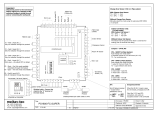
PS2500
13 12 11
0
F1
0
PR
0
F3
F4
0
F5
0
F6
High
0 Y 1 2 3 8 7 0 B A
~
N
0
T3
0
T2
0
T1
P1
P2
P3
+12V
-12V
IR
Main Input
230Vac
Changeover Sensor
Return Air Sensor
Not in use
Medium
Low
CONTROLLER
POWER
SUPPLY
+-
Fuse
8A
MAC Address
JP5
JP4
+12V
0
F2
Occupancy
Sensor
12Vdc
RS485
MAXINET
Protocol
RS485
MAXINET
Protocol
Indoor Sensor
0
Not in use
JP1
Tel: +972 (3) 962 6462
Fax: +972 (3) 962 6620
e-mail: support@meitavtec.com
meitav-tec
PS1807-FC-SUPER
File name: PS1807-FC-SUPER.VSD
Drawn: A.Star
Checked: O.Volovich
Approved: E.Roy
1
2
3
8
7
ETN/X500 or FMH/X500
Thermostat / IR Panel (Option)
On/Off Mode Fan
~
F
16 15 14X2 X1N.C1N.O1
Heat (1A)
Cool (1A)
ON
1 2 4 8 16 32 64 128
RS
Indoor Fan
(230Vac,3A)
Not in use
Not in use
Indoor Coil Sensor (T3) :
( In Heat mode )
With Indoor Coil Sensor !
T3 > 36ºC → Fan ON
T3 < 32ºC → Fan OFF
Without Indoor Coil Sensor
The Indoor Fan will operate when there is a demand for
heating (with 30 seconds time delay)
Jumpers – JP4 & JP5
JP4 – SHORT (4-Pipe System)
Auto change over mode active
2 separate outputs for Cool and Heat (14 & 15)
T2 – for monitoring only
JP4 – OPEN (2-Pipe System)
Auto change over mode not active
1 output for Cool and Heat (15)
T2 – Logic selection (see above)
JP5 - SHORT
In Cool mode – Auto Fan
In Heat mode – Auto Fan
JP5 - OPEN
In Cool mode – Fan ON
In Heat mode – Auto Fan
Occupancy Sensor
When the IR (N.C.) input is open
for 10 minutes, all outputs turn Off.
Short the (-12V) and (IR)
connectors, only when an
occupancy sensor is not connected
Change Over Sensor (T2) in 2-Pipe system:
With Change Over Sensor
T2 < 20ºC → Cool
T2 > 30ºC → Heat
Without Change Over Sensor
Manually select the mode using the wall panel (IRP-X500)
or computer.
JP1
End of Network jumper
– Jumper Short
(Resistance 120 Ω)
JP1 JP1
Open Short
F5 – Short – Fan Only mode available
(Selectable through thermostat)
F5 – Open – Fan Only mode not available
F4 – Fault 1 input (N.C.)
When open – all outputs OFF (no delay)
F6 – Fault 2 input (N.C.)
Only for indication through the protocol
Pump output(1A)
Important !
Disconnect power to the main board
before making any changes to DIP
switches/Jumpers, wiring the unit
and/or connecting the wall panel.
Shielded cable - Connect the
shield to the “8” terminal of
the main board.
5x0.5 12VDC
15.03.0701 Original
02 T3 > 36ºC → Fan ON ; T3 < 32ºC → Fan OFF 17.01.08
Shielded,twisted pair cable 120Ω @ 1MHz
Checksum: 6C50
Software name:0812-217
/