Page is loading ...

Installation, Operation and
Maintenance Manual
FMRO4G-ERP-75
Under the counter Reverse Osmosis System

With proper installation and maintenance, this system will provide you with high quality water for years to come. All of
our water enhancement products are rigorously tested by independent laboratories for safety and reliability.
Operational Parameters ...................................................... 4
Contents of Reverse Osmosis System ...............................4
Tools Recommended For Installation .................................4
Drill a Hole for the Faucet in a Porcelain Sink ....................5
Punch a Hole for the Faucet in a Stainless Steel Sink .......5
Feed Water Valve Installation ............................................. 5
Feed Water Valve Installation Continued ............................6
How to use Quick Connect Fittings on Your RO System ..6
Typical RO Faucet Installation ............................................7
Drain Saddle Installation .....................................................8
System Drain Connection ...................................................8
Green Tube Connection - Feed Water................................9
Tank Valve Installation ......................................................... 9
Yellow Tube Connection - RO Module to Storage Tank ..... 9
Reverse Osmosis Module Mounting ..................................9
Start up Instructions .........................................................10
Six Month Maintenance .................................................... 11
Annual Maintenance ........................................................12
Membrane Replacement .................................................13
Check Air Pressure in the Tank .........................................14
Procedure for Extended Non-Use (More than 2 months) 14
Trouble Shooting .............................................................. 15
Reverse Osmosis System (Diagram / Parts List) .............16
Performance Data Sheet ..................................................17
Arsenic Fact Sheet ............................................................18
Service Record .................................................................19
Limited Warranty ............................................................... 20
Table of Contents
Thank you for your purchase of a state of the art
Reverse Osmosis (RO) water treatment system.
Water quality concerns are becoming more of a focus
for the public. You may have heard about contaminants
in the drinking water, such as Arsenic, Chromium,
Cryptosporidium or Giardia. There may also be some
local water issues such as high levels of Lead and
Copper. This water treatment system has been designed
and tested to provide you with high quality drinking
water for years to come. The following is a brief
overview of the system.
Introduction and General Safety
Please be aware local codes may require this prod-
uct and/or the thermostatic control to be installed
or connected by an electrician.
WARNING
!
WARNING
!
Read this Manual BEFORE using this equipment.
Safety is important to those installing and servicing
a ProMelt
®
panel. Please follow all safety guidelines
in this manual, on the panel directly, as well as any
local or state guidelines.
Failure to read and follow all safety and use infor-
mation can result in death, serious personal injury,
property damage, or damage to the equipment.
Keep this Manual for future reference.
This symbol identies practices,
actions, or failure to act which
could result in property damage
or damage to the ProMelt panel.
This symbol identies hazards
which, if not avoided, could re-
sult in minor or moderate injury.

Your Reverse Osmosis System:
Osmosis is the process of water passing through a semi
permeable membrane in order to balance the concen-
tration of contaminants on each side of the membrane.
A semi permeable membrane is a barrier that will pass
some particles like clean drinking water, but not other
particles like arsenic and lead.
Reverse osmosis uses a semi permeable membrane;
however, by applying pressure across the membrane, it
concentrates contaminants (like a strainer) on one side of
the membrane, producing crystal clear water on the other.
This is why RO systems produce both clean drinking wa-
ter and waste water that is ushed from the system. This
reverse osmosis system also utilizes carbon block ltra-
tion technology, and can therefore provide a higher quality
drinking water than carbon ltration systems alone.
Your system is a four stage RO which is based upon sep-
arate treatment segments within the one complete water
ltration system. These stages are as follows:
Introduction and General Safety
Stage 1
Sediment lter, recommended change 6
months.
The rst stage of your RO system is a ve micron
sediment lter that traps sediment and other par-
ticulate matter like dirt, silt and rust which affect
the taste and appearance of your water.
Stage 2
Carbon lter, recommended change 6 months
The second stage contains a 0.5 micron carbon
block lter. With 20,000 Gallons capacity to
ensure that chlorine, chloramines and other ma-
terials that cause bad taste and odor are greatly
reduced. This lter also reduces Cyst
Stage 3
Membrane, recommended change 2-3 years.
Stage three is the heart of the reverse osmosis
system, the RO membrane. This 75 Gallon per
day semi permeable membrane will effective-
ly take out TDS & Sodium and a wide range of
contaminants such as Percholate, Chromium,
Arsenic, Copper, Lead as well as Cysts, such as
Giardia and Cryptosporidium. Because the pro-
cess of extracting this high quality drinking water
takes time, your RO water treatment system is
equipped with a storage tank.
Stage 4
Carbon in-line lter, recommended change 6 -
12 months.
The nal stage is an in-line granular activated car-
bon (GAC) lter. This lter is used after the water
storage tank, and is used as a nal pol-
ishing lter.
Note: Filter & Membrane life may vary based upon local
water conditions and/or use patterns.
System Maintenance
Just because you can not taste it, does not mean that it
is not there. Contaminants such as Lead, Chromium and
Arsenic are undetectable to the taste. Additionally, over
time if you do not replace the lter elements, other bad
tastes and odors will be apparent in your drinking water.
It is important to change out your lters at the recom-
mended intervals as indicated in this system manual.
When replacing the lter elements, pay special attention
to any cleaning instructions.

Do not use with water that is micro biologically
unsafe or of unknown quality without adequate
disinfection before or after the system.
System is intended to be installed on the cold
water line only.
1 Tank – White (Plastic)
1 Module – White (Filters Pre-Installed)
1 Manual
1 Parts Bag
√ 1 1/4" Hole Saw Bit for Faucet opening *
√ Round Knock out Punch for Stainless
Sinks 1/2” & 1¼” *
√ Adjustable Wrench
√ Sharp Knife
√ 1 / 2" & 5/8" Open End Wrenches
√ Phillips Screw Driver and bit
√ Needle Nose Pliers – Adjustable Pliers
√ Electric Drill
√ 1/8", 1/4" & 3/8" Drill Bits
*Required for faucet installation
Operating Temperatures: Maximum 100°F (37.8°C) Minimum 40°F (4.4°C)
Operating Pressure: Maximum 100 psi (7.0 kg/cm
2
) Minimum 40 psi (2.80 kg/cm
2
)
pH Parameters: Maximum 11 Minimum 2
Iron: Maximum 0.2 ppm
TDS (Total Dissolved Solids) < 1800 ppm
Turbidity < 5 NTU
Hardness: Recommended hardness not to exceed 10
grains per gallon, or 170ppm. System will operate with
hardness over 10 grains but the membrane life may be
shortened. Addition of a water softener may lengthen the
membrane life.
Water Pressure: The operating water pressure in your
home should be tested over a 24 hour period to attain
the maximum pressure. If the incoming water pressure is
above 100 psi then a water pressure regulator is required.
A booster pump is needed for incomming water pressure
under 40psi.
Copper Tubing: Reverse Osmosis water should not be run
through copper tubing as the purity of the water will leach
copper causing an objectional taste in water and pin holes
may form in the tubing. Be sure to follow any state or
local regulations during installation.
Operational Parameters
Contents of Reverse Osmosis (RO) System
Tools Recommended For Installation

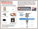
Make sure the surroundings of the sink are
cooled before mounting the faucet to the
sink after drilling and remove all sharp edges.
Step 3
Step 4
Determine desired location for the RO faucet
on your sink and place a piece of masking
tape over where the hole is to be drilled. Mark
the center of the hole on the tape.
Step 1
Using a variable speed drill set on the slowest
speed, drill a
1
/
8
“ pilot hole through both por-
celain and metal casing of sink at the marked
center of the desired location. Use lubricating
oil or liquid soap to keep the drill bit cool (If
drill bit gets hot it may cause the porcelain to
crack or chip).
Using a 1 ¼” hole saw, proceed to drill the
large hole. Keep drill speed on the slowest
speed and use lubricating oil or liquid soap to
keep the hole saw cool during cutting.
Step 2
Punch a Hole for the Faucet in a Stainless Steel Sink
(This system doesn’t come with a faucet. The below notes on the faucet installation are for reference only)
Drill a pilot hole & use the Hole Punch and an
adjustable wrench to punch the hole in the
sink.
Step 5
If mounting faucet to a Stainless Steel Sink you will need
a Hole Punch. The faucet opening should be centered
between the back splash and the edge of the sink, ideally
on the same side as the vertical drain pipe.
Water supply line to the system must be from
the cold water supply line only.
Hot water will severely damage your system.
Conguration for 3/8”
(With Brass Fittings)
* Insert White Washer
Hot
Supply
Cold
Supply
Conguration for 1/2”
(Without Brass Fittings)
Plastic Valve Conguration:
*Washer
Feed Water Valve Installation
Most sinks are pre drilled with 1 ½” or 1 ¼” diameter hole
that you can use for your RO faucet. (If you are already
using it for a sprayer or soap dispenser, see step 1)
Porcelain sinks are extremely hard and can crack or chip
easily. Use extreme caution when drilling.
NOTICE
NOTICE
Drill a Hole for the Faucet in a Porcelain Sink
(This system doesn’t come with a faucet. The below notes on the faucet installation are for reference only)

Turn off the cold water supply to the faucet by
turning the angle stop valve completely off.
Attach the adapt-a-valve as illustrated in the
three photos above, choosing the conguration
that ts your plumbing.
Conguration for 3/8”
compression ttings
Conguration for 1/2”
compression ttings
Hot
Supply
Cold
Supply
Brass Valve Conguration:
Step 6 Step 7
How to use the Quick Connect Fittings on Your RO System
To make a connection, the tube is simply pushed into the
tting. The unique locking system holds the tube rmly in
place without deforming it or restricting ow. Use the steps
below in reference to any quick connect tube connections
throughout this manual.
It is essential that the outside diameter be free of score
marks and that burrs and sharp edges be removed before
inserting into tting.
Fitting grips before it seals. Ensure tube is pushed into the
tube stop.
Push the tube into the tting, to the tube stop. The collet
(gripper) has stainless steel teeth which hold the tube
rmly in position while the O-ring provides a permanent
leak proof seal.
Pull on the tube to check that it is secure. It is a good
practice to test the system prior to leaving site and /or
before use.
To disconnect, ensure the system is
depressurized before removing the tube. Push in the
collect squarely against face of tting. With the collet held
in this position, the tube can be removed. The tting can
then be reused.
Feed Water Valve Installation Continued

3/8” BLUE TUBING FROM
RO MODULE
1/4” RED LINE TO
RO MODULE
3/8” BLUE TUBING FROM
RO MODULE
Drinking Feed Tube Connection
Non Air Gap Faucet
(This system doesn’t come with a faucet. The below notes
on the faucet installation are for reference only)
Locate the 3/8” threaded quick connect tting in the parts
bag. After the faucet has been mounted, thread the tting
on the to faucet stem. Connect the 3/8” blue feed tube to
the 3/8” quick connect tting on the faucet stem. The nal
polishing lter is clipped on to the top of the RO mem-
brane
housing. Attached to the polishing lter is a 3/8” quick
connect tting. Attach the open end of the 3/8” blue tubing
from the RO faucet to the 3/8” quick connect elbow on the
polishing lter.
With Non Air-Gap faucets this will be the only tube con-
nected to the RO faucet.
Air Gap Faucet
(This system doesn’t come with a faucet. The below notes
on the faucet installation are for reference only)
Follow the drinking feed tube connection
instructions above.
3/8” FAUCET CONNECTOR
LOCK WASHER
COUNTER TOP/SINK
ESCUTCHEON PLATE
BLACK RUBBER
WASHER
3/8” BLUE TUBING FROM
RO MODULE
3/8” FAUCET CONNECTOR
LOCK WASHER
COUNTER TOP/SINK
ESCUTCHEON PLATE
BLACK RUBBER
WASHER
3/8” LINE TO DRAIN
SADDLE
Locate the red 1/4” tube in the parts bag and attach one
end to the 1/4” barb on the faucet.
Locate the black 3/8” tube in the parts bag and
attach one end to the 3/8” barb on the faucet.
If your air-gap faucet has no tubes
attached:
Typical RO Faucet Installation
3/8” BLUE TUBING FROM
RO MODULE
1/4” RED LINE TO
RO MODULE
3/8” BLUE TUBING FROM
RO MODULE
Drinking Feed Tube Connection
Non Air Gap Faucet
(This system doesn’t come with a faucet. The below notes
on the faucet installation are for reference only)
Locate the 3/8” threaded quick connect tting in the parts
bag. After the faucet has been mounted, thread the tting
on the to faucet stem. Connect the 3/8” blue feed tube to
the 3/8” quick connect tting on the faucet stem. The nal
polishing lter is clipped on to the top of the RO mem-
brane
housing. Attached to the polishing lter is a 3/8” quick
connect tting. Attach the open end of the 3/8” blue tubing
from the RO faucet to the 3/8” quick connect elbow on the
polishing lter.
With Non Air-Gap faucets this will be the only tube con-
nected to the RO faucet.
Air Gap Faucet
(This system doesn’t come with a faucet. The below notes
on the faucet installation are for reference only)
Follow the drinking feed tube connection
instructions above.
3/8” FAUCET CONNECTOR
LOCK WASHER
COUNTER TOP/SINK
ESCUTCHEON PLATE
BLACK RUBBER
WASHER
3/8” BLUE TUBING FROM
RO MODULE
3/8” FAUCET CONNECTOR
LOCK WASHER
COUNTER TOP/SINK
ESCUTCHEON PLATE
BLACK RUBBER
WASHER
3/8” LINE TO DRAIN
SADDLE
Locate the red 1/4” tube in the parts bag and attach one
end to the 1/4” barb on the faucet.
Locate the black 3/8” tube in the parts bag and
attach one end to the 3/8” barb on the faucet.
If your air-gap faucet has no tubes
attached:
Typical RO Faucet Installation

Drain Saddle Installation - Fits standard
1 ¼” – 1 ½” drain pipes
Step 8
Step 9
Step 10 (cont.)
Step 10 The drain saddle must be mounted at least 1
½” above the nut of the P-trap or cross bar
from the garbage disposal to insure proper
drainage. Assemble the drain saddle around
the drain pipe at the best available location.
The small square black foam gasket with a
circle cut out of the middle must be applied to
the inside of the drain saddle. Remove sticky
tape backing and stick to the drain saddle as
shown.
Locate the drain saddle kit in the parts bag.
Do not over tighten the screws. It may crack the drain
saddle.
With the drain saddle secured
onto the drain pipe, using a 1/4”
drill bit installed in your electric
drill, insert the drill bit through
the opening in the drain saddle
and drill through the drain pipe.
Step 11
It is very important to keep the
drill centered to prevent dam-
age of the drain saddle while
drilling.
Locate the red 1/4” tube in the parts bag. The
permeate pump is mounted on the bottom side
of the system’s metal bracket. Remove the
blue plug from the permeate pump’s 1/4” quick
connect port. Connect one end of the red 1/4”
tube to the open 1/4” port on the permeate
pump.
Next, slip the open end of the red 1/4” tube
through the black compression nut included in
the drain saddle kit. Insert the red 1/4” tube
into the opening of the drain saddle, hand
tighten the black nut, then add 1/4 turn with a
wrench.
The 3/8” drain tube must be as SHORT and STRAIGHT
as possible from the RO faucet to the drain saddle,
making a downward slope from faucet to drain saddle
to allow for proper drainage. This is a gravity fed line
and if there is any bend or dip in the tube, the rinse
water will not flow into the drain properly. Water may
back up and come out the air gap hole in the back of
the faucet.
Step 12
* Non Air-Gap Faucet (This system
doesn’t come with a faucet. The below notes
on the faucet installation are for reference only)
Single Tube (1/4” Drain Saddle):
System Drain Connection
The permeate pump is mounted on the bottom side of the
system’s
metal bracket. Remove the blue plug from the permeate
pump port.
Connect the open end of the red 1/4” tube attached to
the RO faucet to the open 1/4” quick connect port on the
permeate pump.
* Air-Gap Faucet (This system doesn’t come with a
faucet. The below notes on the faucet installation are for
reference only)
Three Tubes (3/8” Drain Saddle):
If your RO faucet is non-air
gap (Single Tube) use 1/4”
Drain Saddle.
If your RO faucet is air gap
(Three tubes) use the 3/8”
Drain Saddle.
Measure the 3/8” drain tube from the RO faucet to the
drain saddle on the drain pipe and make a straight cut to
the correct length. Slip the 3/8” tube open end through
the black compression nut. Insert the 3/8” tube into the
opening of the drain saddle, hand tighten the black nut,
then add 1/4 turn with a wrench.
Feed Water Valve Installation Continued
If you have a garbage disposal, do not install the drain
saddle near it. Installation of the drain saddle must be
either above the garbage disposal, or if a second sink
drain is available, install it above the cross bar on the
second drain. Installation of the drain saddle near a
garbage disposal may cause the drain line to plug.
Using Phillips screw driver tight-
en screws evenly and securely
on both sides of the drain sad-
dle. Keep the plastic compres-
sion nut off at this time.

Step 14
Green Tube Connection - Feed Water
Step 13
Connect the green tube to the RO Module
open elbow on the left side of the unit. Re-
move a brass nut, plastic sleeve and brass
insert from the parts bag. To assemble, place
the brass nut on the green tube rst, then the
sleeve (small tapered end of sleeve must point
to the end of tube) and then push the brass
insert all the way into the end of the tube. (See
Picture)
Insert the green tube into the ¼” opening on
the adapt-a-valve until it stops. Slide the brass
nut and sleeve down and thread onto the male
pipe threads. Use a ½” wrench to securely
tighten the nut.
Reverse Osmosis Module Mounting
Step 21 Determine best location for the RO module to
be mounted to allow for future system main-
tenance. The parts bag has 2 self tapping
screws. Using an electric drill with a Phillips
bit, screw them into the cabinet wall 6” apart
and 16” from the bottom of the cabinet.
Yellow Tube Connection
RO Module to Storage Tank
Step 19
Position the storage tank in desired location.
Measure the yellow tube from Tee tting to
TANK and cut it to desired length if necessary.
Step 18 Locate the 3/8” Yellow tubing. Connect
one open end to the Tee tting on the nal
lter that is clipped on to the RO Membrane
housing.
Insert the open end yellow 3/8” tube into the
3/8” opening on the tank ball valve.
Step 20
Brass Valve:
Plastic Valve:
Step 15 Connect the green tube to the RO Module
open elbow on the left side of the unit. Insert
the open end of the green 1/4” tube into the
open 1/4” quick connect tting on the plas-
tic water feed valve making sure the tube is
pushed in all the way to the tube stop.
Tank Valve Installation
Thread the plastic valve onto the tank tting.
Do not over tighten or the valve could crack.
Step 16
Step 17
Make sure the O-ring is located at the bottom
of the recess for the tank connection.

If you have connected your RO system to a refrigerator
/ ice maker, make sure the ice maker is off (do not allow
water to ow to the ice maker) until ushing (Step 4) is
complete and the tank has been allowed to ll completely.
Connection from the RO to the ice maker system should
have an in-line valve installed before the ice maker so it
can easily be closed to prevent water owing to the ice
maker during start up and periodic maintenance. Your
RO tank must be allowed to ll up fully in order for the ice
maker system to work properly.
After the Tank has lled, open the RO Fau-
cet to ush the tank completely. You will
know that the tank is empty when the ow
rate from the RO faucet is down to a trickle.
Repeat this step two more times. The fourth
tank can be used for drinking.
The ushing process should take about a day
to complete.
Open the RO faucet and leave it open until
water begins to trickle out (it will come out
slowly).
Step 4
Turn on the incoming cold water at the angle
stop valve and open the feed water valve to
the RO system. Check the system for leaks
and tighten any ttings as necessary.
(Check frequently over the next 24 hours to
ensure no leaks are present).
Step 3
Step 2
Step 1
Close the RO faucet allowing the storage
tank to ll with water. It may take 3 to 6
hours to ll the tank completely depending
on the production capability of the mem-
brane, local water temperature and water
pressure.
Flushing of the tank 3 times is only necessary during
the initial startup and after replacing the membrane.
During the ll period you may hear water trickling due to
the Reverse Osmosis Process.
Congratulations!
You have completed the installation of new your Reverse Osmosis system.
Please Follow the Startup Instructions.
NOTICE
NOTICE
NOTICE
Start Up Instructions

Step 1
Step 3
Let system sit for one minute after the tank is
empty to let the system depressurize before
attempting to remove lter housings.
Items needed:
√ Stage 1 - Sediment Filter
√ Stage 2 - Carbon Block Filter
Turn off the incoming water supply to the RO.
Open the RO Faucet and allow water to drain
from the tank until it is completely empty.
Step 2
Water may be saved in a container for drinking or to rinse
system parts.
For more leverage you may leave the RO
module attached to wall of cabinet. If you
are unable to access the module while it is
mounted, remove it prior to changing lters.
Starting with the closest housing (Stage 1),
remove it by turning it clockwise (left), empty
water, then discard lter. Continue on to the
2
nd
housing (Stage 2).
Step 4
Clean the lter housings (bowls) with a mild
soap solution and rinse with water. Check
O-rings and lubricate with water soluble
lubricant. KY Jelly® or other water based
lubricants may be used. Petroleum based
lubricants (such as Vaseline®) must not be
used.
Step 5
Insert a new sediment lter (cloth like ap-
pearance) into the 1st lter housing which is
the one on the water inlet side (white tubing
from the adapt-a-valve) of the RO system and
re-install housing.
Step 6
Insert the new Carbon Block lter (White end
caps & plastic netting) into the second lter
bowl and re-install housing.
Step 7
Step 8
Turn water supply “on” to the RO unit.
Open the RO faucet and leave it open until
water begins to trickle out (it will come out
slowly).
Step 10
Step 9
Close the RO faucet allowing the storage
tank to ll with water. It may take 4 to 6
hours to ll the tank completely depending
on the production capability of the mem-
brane, local water temperature and water
pressure.
*
NOTICE
6 Month System Maintenance
Before re-installing the lter bowls back on to the
system, check O-rings to make sure they are still
in place. *

Step 1
√ Stage 1 - Sediment Filter
√ Stage 2 - Carbon Block Filter
√ Stage 4 - 10” Final Polishing lter
√ 1/2 Cup of hydrogen peroxide or common household bleach.
Sanitizing of unit is recommended.
Perform steps 1 through 5 in the Six Month
System Maintenance (Page 11).
If not sanitizing the system skip to step 8.
Step 3
Step 4
Step 5
Step 6
Remove the RO membrane from its housing
and rest in a clean sanitary place. (Refer to
“Membrane Replacement” section on page
15 for directions on removing the membrane).
Replace cap onto empty membrane housing
and re-connect green tubing.
Step 2
Leaving the lters out, replace stage 2
empty lter housing (hand tight) onto unit.
Measure & pour either 1/2 cup of hydrogen
peroxide or common household bleach into
the 1st lter housing (Stage 1) and hand
tighten onto unit.
With the RO faucet in the closed position
turn on the incoming water supply to the
system by turning the adapt-a-valve count-
er clockwise. Wait 1 minute for the unit to
pressurize. Turn on the RO faucet and let
the water run for 30 seconds. Turn off the
RO faucet and let the unit rest for 2 minutes.
Finally, open the RO faucet and let the water
run for 5 more minutes.
Turn off the incoming water supply to the
system by turning the adapt-a-valve clock-
wise until it stops. Keep the RO faucet open
until the storage tank is completely drained.
Open the membrane housing and re-install
the RO membrane while making sure not to
kink the O-rings. (Refer to “Membrane Re-
placement” section on page 13 for directions
on
installing the membrane). Tighten the cap
back on the housing and reconnect green
tubing.
Step 7
Remove lter housings Stage 1 and 2 and
empty of water.
Insert the new sediment lter (cloth like ap-
pearance) into the 1
st
lter housing which is
the one on the water inlet side (green tubing
from the adapt-a-valve) of the RO system and
re-install housing.
Step 8
Insert the new Carbon Block lter (White End
Caps) into the 2nd housing and
re-install housing.
Step 9
Step 11
Follow Steps 8 through 10 in the Six Month
System Maintenance (Page 11) for startup
directions.
Tip:
This is a good time to check the air pressure
in your storage tank. For instructions please
see page 14.
Step 10 The nal in-line lter is clipped on to the
RO membrane housing. Disconnect all of
the tubes from the in-line lter and unscrew
ttings on each end of the lter and remove
lter from holding clips. Install ttings on to
the new in-line lter and re-connect tubes.
Clip the new in-line lter back on to the RO
membrane housing.
The ow arrow on the in-lter must be pointing away from
the “tee” tting.
Annual Maintenance
Before re-installing the lter bowls back on to the sys-
tem , check O-rings to make sure they are still in place
and lubricate with water soluble lubricant.
NOTICE
NOTICE
NOTICE

Step 5
Step 6
Step 7
Step 8
This reverse osmosis system contains a replaceable com-
ponent (the RO membrane) which is critical to the efcien-
cy of the system. Replacement of this reverse osmosis
membrane should be with one of identical specications
to assure the same efciency and contaminant reduction
performance.
Membranes have a life expectancy between 2 and 5
years, depending on the incoming water conditions and
the amount the RO system is used. This reverse osmosis
membrane is critical for effective reduction of total dis-
solved solids (TDS). The product water should be tested
periodically to verify that the system is performing satis-
factorily.
Normally, a membrane would be replaced during a semi-
annual or annual lter change. However, if at any time
you notice a reduction in water production or an unpleas-
ant taste in the reverse osmosis water, it could be time to
replace the membrane. Watts recommends replacing the
membrane when TDS reduction falls below 75%.
Step 1
Turn off the incoming water supply to the RO
system.
Open the RO Faucet and allow water to drain
from the tank until it is completely empty.
Step 2
Removing the membrane: Installing the membrane:
Remove the end cap from the membrane
housing by turning it counter clockwise to
loosen.
You may remove membrane housing from the
holding clips. Using a pair of pliers, grip the
PVC tube of the RO membrane and pull rmly
on the membrane to remove from the housing
and discard.
Lubricate the O-rings on the new membrane
with a water soluble lubricant such as KY
Jelly ®. Insert the end with the two black
O-rings on the PVC tube rst into the hous-
ing.
Once membrane has been inserted into the
housing you must take your thumbs and give
a rm push to properly seat the membrane.
Replace membrane housing cap and tighten.
After replacing membrane housing into the
holding clips, re-attach the white tube to the
quick connect elbow tting on the end cap of
the membrane housing.
Step 9
Step 3
Remove the polishing lter with clips from the
top of the membrane housing.
Step 4
Disconnect the white tube from the elbow on
the end cap of the membrane housing.
Clip the nal polishing lter back on to the
membrane housing and follow the Start Up
Instructions on page 10.
Step 10
Membrane Replacement

Once all water in the tank is purged, check
air pressure using an air pressure gauge, it
should read between 5 - 7 PSI. (Digital air
pressure gauge is recommended)
Important:
Step 3
Check air pressure only when tank is empty of water!
Step 1 Turn off the incoming water supply to the RO
system.
Open the RO Faucet and allow water to drain
from the tank until it is completely empty.
Step 2
Check air pressure in the storage tank when you notice a
decrease in available water from the RO system. Air can
be added with a bicycle pump using the schrader valve
that is located on the lower side of the tank behind the
blue plastic cap.
Tip:
When water from the RO faucet slows to a
trickle, with the faucet still in the open po-
sition, you may add air to the tank to purge
any left over water, this will ensure that the
tank is completely empty.
Procedure for Extended Non-Use
(More than 2 months)
Turn off the water supply to the RO system and open the
RO faucet to empty the storage tank (Save a few ounces
of RO water). Once the storage tank is empty, remove the
membrane and place it in a sealed plastic bag with the
RO water saved earlier and store in your refrigerator.
For restart, reinstall membrane (See page 13 for mem-
brane installation procedure) and follow startup procedure
on page 10.
7
PSI
Step 4
Follow startup procedure on page 10.
Check Air Pressure in the Tank

TROUBLE SHOOTING
Problem Cause Solution
1. Low/Slow Production Low Water Pressure Assure a minimum of 40 psi incoming water pressure.
Premier sells a booster pump if home water pressure is
low. Make sure water supply is turned on and Adapta
Valve is all the way open.
Crimps in tubing Check tubing and straighten or replace as necessary.
Cloggedpre-lters Replacepre-lters.
Fouledmembrane Replacemembraneandowrestrictor.
2. Milky colored Water Air in system Air in the system is a normal occurrence with initial
startupoftheROsystem.Thismilkylookwill
disappear during normal use within 1-2 weeks. If
conditionreoccursafterlterchange,draintank1to2
times.
3. Water constantly Low water pressure See #1 Above
running,unitwillnot
shut off Crimp in supply tube Check tubing and straighten or repair as necessary.
High water pressure Check incoming water pressure to make sure it does
not exceed 80 psi. A pressure relief valve may be
necessary.
HighpressureinTank Emptystoragetankofwater.Settankairpressure
between 5-7 psi. See previous page.
LowPressureinTank UseaDigitalAirGaugeforbestresults.Theempty
tank pressure should be 5-7 psi. See page 14.
4. Noise / Water from faucet Crimp or restriction Check tubing and straighten or repair as necessary.
vent hole or noise from in drain line Straighten all drain lines. Clear blockage. Cut off any
drain. Excesstubing
Draintubeclogged Causedfromdishwasherorgarbagedisposal.
Disconnectthe3/8”blacklineatthedrain,cleanthe
3/8”blacklineoutwithawire,thenreconnect.Blowing
air through the line will not always remove the clog.
5.Smallamountofwaterin Systemstartingup Normallyittakes4-6hourstolltank.Note:low
storage tank incoming water pressure and/or temperature can
drastically reduce production rate.
Low water pressure See #1 above.
Tomuchairintank Tankairpressureshouldbe5-7psiwhenemptyofwater.
If below 5 psi add air or bleed if above 7 psi.
Check only when tank is empty of water.
See previous page.
6.Waterleaksfromtheblue Notproperlytightened Tightenthebowl.
orwhitelterhousing KinkedO-ring Turnoffthewatersupplyandreleasethepressure.
ReplacetheO-ringifnecessary.Thenlubricateitand
makesuretheO-ringisseatedinthelterbowl
properlybeforereinstallingthelterbowl.
7.Lowwaterowfromfaucet Checkairpressureintank UseaDigitalAirGaugeforbestresults.Theempty
tank pressure should be 5-7 psi. See page 14.

Pre-Filter, sediment FPMB5-978
Pre-Filter, carbon S7722A
Membrane BW60-1812-75
Post Filter AICRO
Faucet FU-WDF-103NSF
Metal Tank FRO-132-WH
Plastic Tank ROPRO4-W
Feed water valve F560080
Components
(This system doesn’t come with a faucet.
The below notes on the faucet installation
are for reference only)
Reverse Osmosis System

Service Record
Date of Purchase:__________ Date of Install:___________ Installed by:__________________
NOTES:
Date
1st stage
Sediment
(6 months)
2 nd stage
Carbon
(6 months)
Final Filter
Carbon
(1 year)
TFC
Mebrane
(2-5 years)

Service Record
Date of Purchase:__________ Date of Install:___________ Installed by:__________________
NOTES:
Date
1st stage
Sediment
(6 months)
2 nd stage
Carbon
(6 months)
Final Filter
Carbon
(1 year)
TFC
Mebrane
(2-5 years)


What your Warranty Covers:
If any part of your Reverse Osmosis System is defective in workmanship (excluding replaceable lters and membranes), return unit after obtaining a return authorization (see below),
less tank, within 1 year of original retail purchase, WATTS will repair or, at WATTS option, replace the system at no charge.
How to obtain Warranty Service:
For warranty service, call 800-659-8400 for documentation and a return authorization number. Once the return authorization number has been created, ship your Reverse Osmosis
unit (less tank) to our factory, freight and insurance prepaid, with proof of date of original purchase. Include a note stating the problem experienced and include your name, address and
your return authorization number. No returns will be accepted with out the proper return authorization number. WATTS will repair it, or replace it, and ship it back to you prepaid.
What this warranty does not cover:
This warranty does not cover defects resulting from improper installation, (contrary to WATTS printed instructions), from abuse, misuse, misapplication, improper maintenance, neglect,
alteration, accidents, casualties, re, ood, freezing, environmental factors, water pressure spikes or other such acts of God.
This warranty will be void if defects occur due to failure to observe the following conditions:
1. The Reverse Osmosis System must be hooked up to a potable municipal or well cold water supply.
2. The hardness of the water should not exceed 10 grains per gallon, or 170 ppm.
3. Maximum incoming iron must be less than 0.2 ppm.
4. The pH of the water must not be lower than 2 or higher than 11.
5. The incoming water pressure must be between 40 and 85 pounds per square inch.
6. Incoming water to the RO cannot exceed 105 degrees F (40 degrees C.)
7. Incoming TDS/Total Dissolved Solids not to exceed 1800 ppm.
8. Do not use with water that is micro biologically unsafe or of unknown quality without
adequate disinfection before or after the system.
This warranty does not cover any equipment that is relocated from the site of its original installation.
This warranty doe not cover any charges incurred due to professional installation.
This warranty does not cover any equipment that is installed or used outside the United States of America and Canada.
LIMITATIONS AND EXCLUSIONS:
WATTS WILL NOT BE RESPONSIBLE FOR ANY IMPLIED WARRANTIES, INCLUDING THOSE OF MERCHANTABILITY AND FITNESS FOR A PARTICULAR PURPOSE. WATTS WILL NOT BE
RESPONSIBLE FOR ANY INCIDENTAL OR CONSEQUENTIAL DAMAGES, INCLUDING TRAVEL EXPENSE, TELEPHONE CHARGES, LOSS OF REVENUE, LOSS OF TIME, INCONVENIENCE, LOSS
OF USE OF THE EQUIPMENT, AND DAMAGE CAUSED BY THIS EQUIPMENT AND ITS FAILURE TO FUNCTION PROPERLY. THIS WARRANTY SETS FORTH ALL OF WATTS RESPONSIBILITIES
REGARDING THIS EQUIPMENT.
OTHER CONDITIONS:
If WATTS chooses to replace the equipment, WATTS may replace it with reconditioned equipment. Parts used in repairing or replacing the equipment will be warranted for 90 days from
the date the equipment is returned to you or for the remainder of the original warranty period, whichever is longer. This warranty is not assignable or transferable.
YOUR RIGHTS UNDER STATE LAW:
Some states do not allow limitations on how long an implied warranty lasts, and some states do not allow the exclusion or limitation of incidental or consequential damages, so the above
limitations or exclusions may not apply. This warranty gives you specic legal rights, and you may have other legal rights which vary from state to state.
IOM-WQ-FMRO4G-ERP 1827
EDP 199626
© 2018 Watts
USA: T: (978) 689-6066 • F: (978) 975-8350 • Watts.com
Canada: T: (905) 332-4090 • F: (905) 332-7068 • Watts.ca
Latin America: T: (52) 81-1001-8600 • Watts.com
FMRO4G-ERP-75
Limited Warranty
/