Page is loading ...

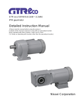
Tsubaki
Helical Gear Shaft-mounted
Reducer
SMR Series
Instruction Manual
Thank you for purchasing the Tsubaki SMR
Series Helical Gear Shaft-mounted Reducer.
In order to fully realize the characteristics of this
reducer, please read this manual carefully and use
it for installation and inspection. Please ensure
that this manual is delivered to the customer who
will use the reducer.
1. When purchased
Inspect the following items upon receipt of your reducer.
1) Verify that the specifications on the nameplate correspond to
your order.
Note) Pay special attention mounting direction. Check this against the position
of the oil gauge and plugs. For the B type, also check the rotation
direction of the backstop cam clutch.
(The SM100 and 103 can be mounted in all directions and have no oil
gauge.)
2) Make sure all accessories, such as pressure vents, are included.
(The SM100 and 103 use grease lubrication and have no
pressure vent.)
3) Check for any scratches or cosmetic defects caused during
transport.
4) Check that no bolts are loose.
If you find any problems, please contact the dealer where the
reducer was purchased.
2. Installation
(1) Ambient conditions
The area of installation for the reducer should have an ambient
temperature of 0 to 40°C, be well-ventilated, low in humidity, and
have little or no dust. Do not use the reducer in locations with
corrosive liquids or gases, or in flammable or explosive
locations.
If the reducer is to be used outdoors, furnish a cover or similar
protection to avoid direct exposure to rain.
(2) Transport
Be sure to use the eye-bolts or lifting rings on the top surface of
the housing when transporting the reducer. Never hook wires or
slings to the input/output shafts. Doing so may make the shaft
eccentric or cause other problems which will shorten the life of
the reducer or cause it to fail.
Note) The SM100 to 107 have no eye-bolts.
(3) Mounting to the driven shaft
●
The shaft to which the reducer is to be mounted should be g7.
The hollow shaft bore is finished to H7 or H8. Refer to the
following table for the length of the driven shaft.
<Recommended driven shaft length>
100
103
107
115
203
207
215
307
315
407
415
507
608
Straight shaft
68
76
103
116
133
150
165
201
232
-
-
-
-
Taper bush
- - 97
113
130
144
160
187
212
206
254
286
305
●
The SM100 and 103 can be mounted in any direction. The
SM107 to 608 are shipped as mounting example 1 unless a
mounting example has been indicated when ordered.
Contact us if the mounting example is different.
●
The position of the oil gauge and plugs in the mounting
examples in the table to the right for the SM107 to 315 is when
the inclined surface is within ±10° from the mounting example.
When ±10° is exceeded or when the mounting example is
changed, the position of the oil gauge and plugs will change.
Please contact us.
The SM407 to 608 are handled as necessary. Refer to the
external diagrams.
Mounting examples
Standard mounting examples Special mounting
examples
(3-1) Straight shaft series
●
Mount as outlined here.
Steps
Mounting procedures
1
Install the key on the driven shaft.
Note) Use a bar key. Do not use a tapered or gib headed key. Doing
so may make the output shaft eccentric or cause other problems
which will shorten the life of the reducer or cause it to fail.
2
For SM100 to 107, insert it onto the driven shaft as is. For SM115 to
608, insert it onto the driven shaft by hoisting it with the eye-bolts or
lifting rings on the top of the housing.
Align the phase of the key before inserting it.
Note) If the shaft fits too tightly, help the hollow output shaft slide
smoothly by lightly tapping the edge with a plastic hammer.
(Apply grease or molybdenum disulfide to the driven shaft.)
Be careful not to damage the oil seal.
3
Use an end plate to fix the reducer and driven shaft in the thrust
direction.
The end plate can be fixed on the driven shaft with a stop ring in the
stop ring groove of the hollow output shaft, or by fixing it to the end of
the shaft, but taking disassembly into consideration, we recommend
the method securing the stop ring and end plate.
Place a stop ring in the stop ring groove on the hollow output shaft and
mount the end plate on the reducer output shaft side of the stop ring.
Then fix the end plate to the driven shaft with hex bolts.
Recommended end/draw plate dimensions
Size
Plate Bolt for plate
(with spring
washer)
Stop ring size
φD T H Z
2-Y hole
P
SM100
φ24.6
7 21 M8 5.5 16 2-M 5 x 30 mm
C25
φ29.6
7 26 M8 5.5 20 2-M 5 x 30 mm
C30
SM103
φ34.6
10 30 M12
6.6 22 2-M 6 x 35mm C35
SM107
φ39.6
10 35 M12
6.6 25 2-M 6 x 35mm C40
SM115
φ44.6
12 39 M16
9 28 2-M 8 x 45mm C45
SM203
φ54.6
14 48 M16
11 32 2-M10 x 55 mm
C55
SM207
φ64.6
14 57 M24
14 40 2-M12 x 60 mm
C65
SM215
φ74.6
14 67 M24
14 48 2-M12 x 60 mm
C75
SM307
φ84.6
17 75 M30
14 55 2-M12 x 65mm
C85
SM315
φ94.6
17 85 M30
18 60 2-M16 x 75mm
C95
●
If the driven shaft is vertical and points down
Use the stop ring and bolts as shown in the figure to prevent the
reducer from falling off, and take all safety precautions necessary.
●
If the driven shaft faces up
Machine a shoulder on the driven shaft as shown in the figure to
prevent movement in the thrust direction.
(Oil filling port)
(Oil filling port)
(Oil filling port)
Pressure vent
Oil gauge
Top
Top
Pressure vent
Oil gauge
Pressure vent
Oil gauge
Top
(Oil filling port)
(Oil filling port)
End/draw plate
Stop ring
Bolt for end plate
Output shaft
Driven
shaft
Z tap
2-Y hole
Stop ring
Hollow output shaft
Driven
shaft
Oil gauge
Pressure vent
Top
Top
Pressure vent
Oil gauge
Top
(Oil filling port)
Pressure vent
Drain plug
Drain plug
Drain plug
Oil gauge
Drain plug
Drain plug
Drain plug

(3-2) Taper bush series
●
For the taper bush, there is Type I (separate driven shaft key and
hollow output shaft key) and Type II (combined driven shaft key and
hollow output shaft key) according to the reducer size and hollow
shaft bore diameter.
●
Mount as outlined here.
Steps
Type I Type II
1 Wipe dust and oil off of the driven shaft, taper bush, and hollow output
shaft.
2
Install the driven shaft key on the
driven shaft.
Install the combined key on the
driven shaft.
3 Insert the taper bush onto the driven shaft.
Align the phase of the key before inserting it.
4 Install the hollow output shaft key on
the taper bush.
5
Hoist the reducer with the eye-bolts or lifting rings on the top of the
housing and insert the taper bush.
Align the phase of the key before inserting it.
6 Align the flange screw holes with the taper bush mounting bolts and
tighten.
7 First check that the reducer is in the correct position on the driven shaft,
then evenly tighten the mounting bolts.
8
After tightening the bolts, verify that the end face of the hollow output
shaft is not interfering with the taper bush. (If it interferes, the driven
shaft diameter may be too small, or the mounting bolts may not have
been tightened evenly)
Note) When removing the reducer from the driven shaft, the mounting bolts must be removed
and inserted in the tap. Provide enough room to remove the bolts by referring to the
taper bush bolt lengths and PCD.
Recommended taper bush mounting bolt tightening torque
Size SM107
SM115
SM203
SM207
SM215
SM307
Bolt size M6 M6 M8 M8 M10 M10
Tightening
torque N·m
(kgf·m)
13.7
(1.4)
13.7
(1.4)
34.3
(3.5)
34.3
(3.5)
67.6
(6.9)
67.6
(6.9)
Size SM315
SM407
SM415
SM507
SM608
Bolt size M10 1/2" 5/8" 3/4" 3/4"
Tightening
torque N·m
(kgf·m)
67.6
(6.9)
95.1
(9.7)
196
(20)
343
(35)
343
(35)
Note) Value per bolt.
(4) Fixing
The S and B type reducers are fixed with tie rods and the F type
reducer is fixed with the housing flange.
(4-1) Tie rod mounting
●
These procedures describe mounting the tie rod to the reducer.
SM100 to 315
Steps
Mounting procedures Mounting diagram
1
First remove the tie rod bolt (1)
from the reducer housing.
2 Attach the tie rod collar (3) to the
tie rod (4).
3
Pass the tie rod bolt (1) through
the reducer housing bolt hole →
tie rod collar (3) → reducer
housing bolt hole, and then
secure with the U nut (2).
*
Do not loosen both tie rod
bolts at the same time.
4
After attaching the lock nut (5) to
the tie rod (4), attach the
turnbuckle (6).
SM407 to 608
Steps
Mounting procedures Mounting diagram
1
First remove tie rod bolt A (3) from the
reducer housing.
* Do not loosen both tie rod
bolts at the same time.
2
Pass tie rod bolt A (2) through washer A
(7) → tie rod plate (1) → reducer housing
bolt hole → tie rod plate (1) → washer A
(7), and then secure with nut A (5).
3
Pass tie rod bolt B (4) through washer B
(8) -> tie rod plate (1) → tie rod (2) → tie
rod plate (1) → washer B (8), and then
secure with nut B (6).
Recommended tie rod bolt, tie rod bolt A tightening torque
Size SM100
SM103
SM107
SM115
SM203
SM207
SM215
Bolt size M6 M8 M8 M10
M12
M16
M16
Tightening
torque N·m
(kgf·m)
4.9
(0.5)
12
(1.3)
12
(1.3)
25
(2.6)
44
(4.5)
108
(11)
108
(11)
Size SM307
SM315
SM407
SM415
SM507
SM608
Bolt size M20 M20 5/8" 3/4" 3/4" 3/4"
Tightening
torque N·m
(kgf·m)
196
(20)
196
(20)
98
(10)
167
(17)
167
(17)
167
(17)
SM407 to 608 tie rod bolt B size
Size SM407 SM415 SM507 SM608
Bolt size 1" 1 1/4" 1 1/4" 1 1/4"
Tightening torque N·m
(kgf·m)
313
(32)
431
(44)
431
(44)
431
(44)
●
Tie rod mounting direction
The tie rod is ideally mounted as shown
in the figure to the left so that it is
subjected to tension. The arrow shows
the output rotation direction and the
direction of the force that the tie rod is
subjected to.
●
Recommended tie rod mounting angle range
(4-2) Flange mounting
●
Install on a smooth flat installation surface that can easily
withstand the weight of the equipment.
●
Use bolts compliant to JIS strength class 10.9T for mounting.
●
Mount as outlined here.
Steps
Mounting procedures
1 Free the driven shaft in the thrust direction.
2 Insert the reducer onto the driven shaft.
3 Mount the reducer to the flange surface.
4 Fix the reducer in the thrust direction of the driven shaft. For the
taper bush series, tighten the taper bush.
5 Fix the driven shaft in the thrust direction.
Note) If the reducer is mounted on its flange surface or the taper bush is
tightened after the reducer is fixed to the driven shaft in the thrust direction,
the bearings on the reducer or the driven shaft will be subject to thrust
force which could result in reduced life or machine failure.
Hollow
output
shaft
Driven shaft
Taper bush
Driven shaft
Driven shaft key
Hollow output shaft key
Flange
Tightening bolt

Note) When the output shaft is subjected to a radial load, verify that it is less
than the allowable radial load. When it is subjected to a thrust load, please
contact us.
Recommended mounting bolts
Size 100 103 107 115 203 207 215
Bolt size M6 M8 M8 M10
M12
M16
M16
Size 307 315 407 415 507 608
Bolt size M20 M20 M20 M20 M20 M20
Note) Determine the bolt length according to the plate thickness on the side of
the driven machine.
(5) Connection
●
Use caution so as to not bend the shaft or damage the bearings
when attaching pulleys, sprockets, and couplings during reducer
input.
●
Align accurately. Any eccentricity in the shafts or an overhanging
load greater than the allowable value will shorten the service life of
the gears, bearings, and shaft, resulting in vibration and noise.
(6) Removal
(6-1) Straight shaft series
●
When removing the reducer from the driven shaft, supply your
own jack bolt and stopper, as illustrated in the figures below, with
an end/draw plate (explained earlier) and a stop ring. (The driven
shaft length is the recommended driven shaft length explained
earlier.)
●
Remove as outlined here.
Steps
Removal procedure
1 Loosen the hex bolt used to fix the end plate, and remove the end
plate.
2 Mount the end/draw plate and stopper on the driven shift side.
3 Insert the jack bolt in the tap on the draw plate and pull the reducer
from the driven shaft.
(6-2) Taper bush series
●
Remove as outlined here.
Steps
Removal procedure
1 Remove the taper bush mounting bolts and insert them in the removal
taps in two locations on the taper bush.
2 Suspend the reducer with the eye-bolts or lifting rings.
3 Tighten the bolts and push the hollow output shaft flange to start to
push out the reducer.
4 Hoist up the reducer with the eye-bolts or lifting rings to remove.
3. Lubrication
(1) Introduction
●
The SMR Series is filled with grease (for SM100 and 103,
NIGTIGHT LMS No. 000) or lubrication oil (for SM107 to 608,
Shell Omala S2 G 150) when shipped from the factory and
should be used as is.
However, you should still check the oil level in the oil gauge
after you finish mounting the reducer. If the oil level does not
appear in the oil gauge, fill with the same brand of lubrication oil
until it is visible.
●
Even when the oil level falls below the oil gauge when changing
the oil or when the oil has decreased due to whatever
conditions, the remaining oil will occasionally appear to be
remaining at the lower end of the oil gauge due to surface
tension. Therefore, in managing the oil level, please check that
the oil level is maintained in the middle of the oil gauge.
●
The B type backstop cam clutch section has also been filled
with grease (for SM107 to 315, Esso Beacon 325) or lubrication
oil (for SM407 to 608, Mobil ATF 220) and should be used as
is.
●
For the SM107 to 608, be sure to replace the plug on the oil
filling port with the supplied pressure vent.
Plug size (filling, drain)
Size 107
115
203
207
215
307
315
407
415
507
608
Plug sizes
1/4"
3/8"
3/8"
1/2"
1/2"
3/4"
3/4"
3/4"
3/4"
3/4"
3/4"
(Note) For a mounting direction other than that ordered, the reducer will have
a different amount of lubrication oil, and the oil gauge and plugs will
also be in different positions.
(Note) Contact us if the ambient temperature is less than 0°C or greater than
40°C.
(Note) When the SM107 to 608 are used at input speeds slower than 500
r/min, switch to recommended oil described in the following table.
(Note) When the SM107 to 608 are used in mounting example 1 at input
speeds faster than 1000 r/min and under continuous operating
conditions, the temperature of the reducer may increase. Before use,
we recommend adjusting the oil level with the following procedure. In
the mounting example 1 position, remove plug A in mounting example
1, and then drain the filled lubrication oil to the plug A level. Next,
remove the oil gauge and install it in the plug A position, and install
plug A in the position where the oil gauge was.
(2) Oil replacement
●
The grease in the SM100 to 103 does not require replacement.
●
Replace the oil in the SM107 to 608 every 1000 to 2000 hours
after starting operation with the following procedure.
Steps
Replacement procedures
1
Perform the oil replacement when the machine is stopped.
Warning) The housing and oil are very hot immediately after
stopping operation. Wait for the housing surface to
cool before replacing the oil.
2 Have a drip pan ready and place it under the reducer's drain
plug.
3
Remove the drain plug with an Allen key wrench to drain the
oil. Remove the pressure vent to allow the oil to drain
quickly.
Note) Do not loosen the drain plug all at once. Otherwise, oil may
splash out.
4
Apply sealant to the drain plug and fully tighten it in place.
Note) Shin-Etsu silicone one-component RTV rubber or an
equivalent product is recommended for the sealant.
5
Check the mounting direction examples and refer to the
following tables to determine the proper oil volume. Pour the
recommended oil into the oil inlet until visible in the oil
gauge.
Note) If the reducer is mounted at a sharper angle than shown in
the mounting examples, fill with a little more oil than
indicated below.
6 After filling, attach the pressure vent.
Recommended oil
Input speed
500 to 1750 r/min 500 r/min or lower
Ambient
temperature 0 to 35°C 35°C to 60°C
0 to 35°C 35°C to 60°C
Type 2 industrial
gear oil ISO VG 150 ISO VG 220 ISO VG 220 ISO VG 320
Exxon Mobile
Mobile Gear
600XP-150
Mobile Gear
600XP-220
Mobile Gear
600XP-220
Mobile Gear
600XP-320
Showa Shell
Shell Omala
S2G150
Shell Omala
S2G220
Shell Omala
S2G220
Shell Omala
S2G320
Idemitsu
Daphne Super
Gear Oil 150
Daphne Super
Gear Oil 220
Daphne Super
Gear Oil 220
Daphne Super
Gear Oil 320
COSMO Oil
COSMO Gear
SE 150
COSMO Gear
SE 220
COSMO Gear
SE 220
COSMO Gear
SE 320
Lubrication oil volume
Size
Mounting
examples
SM107
SM115
SM203
SM207
SM215
SM307
Standard
1
1.0 (0.7)
1.3 (0.9)
1.9 (1.3)
3.0 (2.0)
3.7 (2.4)
6.3 (4.1)
2
1.1 1.5 2.1 3.7 4.8 8.5
3
0.9 1.2 1.7 3.0 4.0 6.9
4
0.8 1.0 1.4 2.5 3.2 5.8
Special
5
1.1 1.5 2.1 3.7 4.8 8.5
6
1.0 1.4 2.0 3.5 4.4 8.0
Size
Mounting
examples
SM315
SM407
SM415
SM507
SM608
Standard
1
9.7 (5.7)
15 (6.5)
24 (10)
37 (13)
55 (24)
2
12 15 24 37 55
3
10 15 24 37 55
4
8.2 15 24 37 55
Special
5
12 21 27 36 49
6
12 21 27 36 49
Recommended jack
bolt
Size Jack bolt
(fully threaded)
SM100 M8 x 60 mm
M8 x 60 mm
SM103 M12 x 80mm
SM107 M12 x 80mm
SM115 M16 x 100 mm
SM203 M16 x 100 mm
SM207 M24 x 150 mm
SM215 M24 x 150 mm
SM307 M30 x 180 mm
SM315 M30 x 180 mm
Locking bolt
Hollow output shaft
Jack bolt
End/draw plate
Stop ring
Driven shaft

Note) The mounting example ( ) value is when the oil gauge is changed to the
plug A position in mounting example 1 when the reducer is used at an
input shaft speed of 1000 r/min or higher and under continuous operating
conditions.
(3) Replacing grease, lubrication oil in the backstop cam clutch
●
Replace the grease and lubrication oil once every one or two years
with the following procedure.
SM107 to 315
Steps
Replacement procedures Notes
1
First remove the
input cap mounting
bolt and remove
the input cap.
Do not tap with an iron
hammer.
2
Remove the cam
clutch from the
shaft while gently
turning it in the idle
direction.
Do not apply excessive
force to the bush. There
is a risk of damaging the
cam clutch.
3
Apply the specified
amount of grease
to the sliding
surface of the cam
clutch cam.
Always apply the
specified amount of the
recommended grease.
An excessive application
of grease will cause heat
to be produced.
4
Attach the cam
clutch to the shaft
while gently turning
it in the idle
direction.
Do not force it when stiff
and it cannot be inserted
onto the shaft. There may
be a problem with the
cam clutch.
5
Align the keyway
on the input cap
and the key phase
of the cam clutch
and attach the
input cap with the
mounting bolt.
Make sure the cam clutch
has entered the reducer
properly, then tighten the
mounting bolt to fix.
Input cap mounting bolt size
Size
SM107
SM115
SM203
SM207
SM215
SM307
SM315
Bolt size
M6 M6 M6 M8 M8 M10
M10
SM407 to 608
Steps
Replacement procedures Notes
1
First remove the drain
plug from the cam
clutch, then drain the
old oil.
After draining the oil, it is
more effective to rinse
the interior with white
kerosene.
2
Reattach the drain plug.
Always apply a sealant
to the drain plug and
fully tighten it.
3
Fill from the filling plug
with the specified
volume of new oil.
Always fill with the
recommended
lubrication oil.
4
After you check the oil
level with the oil gauge,
attach the filling plug.
Excessive oil will cause
heat to be produced.
Filling, drain plug sizes
Size SM407 to 608
Plug sizes PT 1/8
Recommended grease, lubrication oil
Size SM107 to 315 SM407 to 608
Brand
Esso Beacon 325 (grease) Mobil ATF 220 (lubrication oil)
Note) The brand of grease and lubrication oil is extremely important for the
performance and service life of the cam clutch. Use only the above grease
and lubrication oil recommended by Tsubaki E&M. Do not mix other
brands of oil or use grease or lubrication oil that contains
extreme-pressure additives.
There is a risk that the cam clutch will not function properly.
Grease/lubrication oil volumes
Unit: g
Size SM107
SM115
SM203
SM207
SM215
SM307
SM315
Grease
volume 11 11 14 17 27 31 40
Unit: L
Size SM407 SM415 SM507 SM608
Lubrication
oil volume
0.2 0.2 0.5 0.5
4. Operation
1) Inspecting prior to use
Upon completing the installation, check the following prior to
operation:
• Is the direction of rotation is correct?
• Is the connection to the driven shaft secure?
• Are there any loose mountings or bolts?
• Make sure the equipment incorporates failsafe measures to
prevent accidents from occurring due to the use of the reducer,
or in the event the reducer malfunctions.
2) Trial run
Before running in production, run the reducer without loading.
Check for abnormalities such as vibration, noise, and heat.
Gradually increase the load.
3) Production run
Verify the following after starting production:
• Is the direction of rotation is correct?
• Is there any abnormal vibration, noise, heat, etc?
• Is the reducer subject to shock or overloads?
Note) Loading the reducer above the allowable capacity can shorten the life
of the gears and other parts, resulting in damage to the reducer. Do not
load the reducer above its allowable torque.
Note) The reducer may generate heat during the first two or three days of
operation. This is expected and is not a problem.
However, if the housing temperature exceeds 93°C, it could
indicate an incorrect oil level or improper installation. Check
each location. Note, do not touch the reducer with your bare
hands when checking. Doing so may cause burns.
5. Maintenance
1) Maintenance
• When performing maintenance, wear suitable clothing and use
protection including safety glasses, gloves, safety shoes, etc.
• To prevent secondary accidents, keep the surrounding area
safe and tidy.
• Always turn the power off and wait for the machine to come to
a full stop. Also, use lock-outs to prevent unintentional power
supply.
• The reducer reaches extremely high temperatures during
operation. Do not touch with your bare hands.
• Read and follow labor safety codes and standards.
2) Maintenance items
Make daily inspections using appropriate measuring
instruments for the following procedures. Take note of
operating conditions when performing maintenance.
Item Details
Noise Is the noise louder than usual? Are
there unusual periodic noises?
Vibration Are there any unusual vibrations?
Temperature rise
Is there an unusual increase in
temperature?
Lubrication oil
leak
Is oil leaking from the oil seal or
couplings?
Note) (1) When a problem occurs, immediately stop operation and
perform a detailed inspection.
(2) If the cause is unclear or repairs are not possible,
consult the dealer where the reducer was purchased.
Oil plug
Oil gauge
Drain plug
Cam
Key position
Input cap
Cam Clutch

6. Construction diagram
(B type, 2-stage reduction taper bush specification)
Safety precautions
Thank you for your patronage.
In order to use this reducer safely, always observe the following items.
● An experienced technician should perform any work when
handling the SMR Series. The content listed in this instruction
manual must also be carefully read and fully understood before
using the reducer.
● Please ensure that this instruction manual is delivered to the
customer who will use the reducer.
● Carefully store the instruction manual so that it can be used at any
time before handling the reducer.
● The degree of harm and damage that can be expected to occur
when the reducer is mishandled is essentially classified into the
ranks of "DANGER" and "CAUTION", and these are indicated in
the instruction manual. The definitions and indications are as
follows.
DANGER
This indicates the possibility that a
dangerous situation may occur, resulting
in death or serious injury if the reducer is
mishandled.
CAUTION
This indicates the possibility that a
dangerous situation may occur, resulting
in a moderate or light injury, or resulting
in only physical damage, if the reducer is
mishandled.
Depending on the situation, even items listed under CAUTION may
result in serious consequences.
Both indicate important content that must always be observed.
DANGER
(Overall)
• Work to transport, install, run tubing, wire, run/operate, and
maintain/inspect the reducer must always be performed by a
technician with specialized knowledge and skills. Otherwise there
is a risk of injury and damage to equipment.
• When the reducer is installed in equipment to transport people,
always install protective devices for safety on the equipment
side.
Otherwise there is a risk of accidents due to runaway equipment
and damage to equipment.
• When the reducer is used in lift equipment, always install safety
devices to prevent drops on the equipment side. Otherwise there
is a risk of accidents and damage to equipment due to the lift
falling.
(Installation)
• When hoisting the reducer to transport it, do not enter the area
underneath it. Otherwise there is a risk of accidents due to the
reducer falling.
(Operation)
• During operation, do not get near or touch any rotating bodies
(shafts or other parts). Otherwise there is a risk of being caught
in those parts resulting in injury.
(Daily inspection and maintenance)
• In maintenance and inspection during operation, do not touch
any rotating bodies (shafts or other parts). Otherwise there is a
risk of being caught in those parts resulting in accident.
• When entering the inside of the product to inspect it while
stopped, first confirm that the rotation of the motor and the driven
machine has stopped, and sufficiently cool the inside of the
product, and then you must work while ventilating the interior.
While performing the inspection work, arrange personnel for
confirming safe working conditions on the exterior, and always
confirm safety with the worker. Be aware that the product interior
is slippery from lubrication oil and take sufficient safety
precautions. Otherwise there is a risk of accidents.
CAUTION
(Overall)
• Do not use the reducer outside of the specifications listed on the
SMR Series nameplate or the reducer specifications in
manufacturing specification document. Otherwise there is a risk
of injury and damage to equipment.
• Do not insert fingers or objects into the openings on the SMR
Series. Otherwise there is a risk of injury and damage to
equipment.
• Do not use the SRM Series when damaged. Otherwise there is a
risk of injury and damage to equipment.
• Do not remove the nameplate.
• Alterations to the reducer by the customer are not covered by the
warranty and Tsubaki E&M assumes no responsibility for them.
(Upon receipt of your reducer)
• Check the orientation of the packaging and open it. Otherwise there is a
risk of injury.
• Make sure the model number of the unit delivered matches your order. If
the wrong reducer is installed, there is a risk of injury and damage to
equipment.
(Transport)
• Use caution when transporting the reducer as it is dangerous if it
drops or falls over. If the SMR Series has lifting rings, always use
those lifting rings. However, after the reducer is installed in the
machinery, do not hoist the machinery itself with the lifting rings.
Before hoisting the reducer, check the SMR Series weight on the
nameplate, packaging, external diagram, catalog or other
documents, and do not suspend a reducer that exceeds the
weight rating of the lifting rings. Otherwise there is a risk of
damaging the lifting rings, injury from the reducer falling over,
and damage to equipment.
(Installation)
• Do not place obstructions around the SMR Series that will
interfere with ventilation. This will hinder cooling and may result
in burns or a fire due to abnormal heating.
• Do not get on the SMR Series or hang from it under any
circumstances. Otherwise there is a risk of injury.

• Do not touch the keyways on the ends of the shafts of the SMR
Series with bare hands. Otherwise there is a risk of injury.
• For equipment that is averse to greasiness such as food
machinery, take precautions for an accidental oil leak due to
breakdown or service life and install damage prevention
equipment such as an oil pan. Otherwise there is a risk the
reducer may become faulty due to an oil leak.
- Mounting to the driven shaft -
• Check the direction of rotation before connecting the reducer to
the driven machine. There is a risk of injury and damage to
equipment by mistaking the direction of rotation.
• Lightly tap the end of the output shaft with a plastic hammer to
insert it. Do not tap the casing or the oil seal.
• Always secure the shaft to the driven shaft to prevent them from
coming apart.
(Connection)
- Connection to a motor -
• When connecting the SMR Series to a motor, pay careful
attention to centering, belt tension, and the parallelism of the
pulleys. When directly connected, pay careful attention to the
accuracy of the direct connection. When belt driven, correctly
adjust the belt tension. Before operation, ensure that the tie bolts
for the pulleys and couplings have been fully tightened.
Otherwise there is a risk of injury and damage to equipment due
to flying debris.
• Install a cover so that rotating components will not be touched.
Otherwise there is a risk of injury.
• When the SMR Series will rotate independently, remove the key
that is temporarily installed to the output shaft. Otherwise there is
a risk of injury.
(Operation)
• During operation, the SMR Series reaches high temperatures.
Use caution not to touch the reducer with your hands or body.
Otherwise there is a risk of burns.
• When a problem occurs, immediately stop operation. Otherwise
there is a risk of injury.
• Do not use the reducer with a load that exceeds the rated load.
Otherwise there is a risk of injury and damage to equipment.
Do not loosen the oil plugs during operation. Otherwise
lubrication oil may spray out resulting in burns.
• When running the reducer in reverse, first stop it, and then run it
in reverse. Forward and reverse operation by plucking may
damage the SMR Series and the driven machine.
(Daily inspection and maintenance)
• Change the lubrication oil and grease according to the instruction
manual. Always use the type of oil recommended by the
manufacturer. Otherwise there is a risk of damage to equipment.
• The surface of the SMR Series reaches high temperatures, so do
not touch it bare hands. Otherwise there is a risk of burns.
• Do not change the lubrication oil or grease during operation or
immediately after stopping. Otherwise there is a risk of burns.
• Diagnose problems that occur based on the instruction manual.
Do not operate the reducer until the cause of the problem has
been determined and action has been taken.
(Disassembly/assembly)
• Repair, disassembly, and assembly should always be performed
by a specialist. Otherwise there is a risk of injury and damage to
equipment.
(Disposal)
• The SMR Series and its lubrication oil should be treated as
general industrial waste.
Limited Warranty
Tsubaki E&M Co.: hereinafter referred to as “Seller”
Customer: hereinafter referred to as “Buyer”
Goods sold or supplied by Seller to Buyer: hereinafter referred to as “Goods”
1.
..
. Warranty period without charge
18 months effective the date of shipment or 12 months effective
the first use of Goods, including installation of Goods to Buyer’s
equipment or machine - whichever comes first.
2.
..
. Warranty coverage
Should any damage or problem with the Goods arise within the
warranty period, given that the Goods were operated and
maintained according to the instructions provided in the manual,
Seller will repair and replace at no charge once the Goods are
returned to the Seller.
This warranty only covers individual Goods supplied by the
Seller to the Buyer and therefore does not include the following:
(1) Any costs related to the removal or re-installation of Goods
from the Buyer’s equipment or machine to repair or replace
parts.
(2) Cost to transport Buyer’s equipment or machines to repair
facility.
(3) Costs to reimburse any profit loss due to any repair or
damage and consequential losses caused by the Buyer.
3.
..
. Warranty with charge
Seller will charge for any investigation and repair of Goods
(even during the warranty period without charge) caused by:
(1) Improper installation by failing to follow the instruction
manual.
(2) Insufficient maintenance or improper operation by the
Buyer.
(3) Incorrect installation of Goods onto other equipment or
machines.
(4) Structure change of the Goods by any modifications or
alterations by the Buyer.
(5) Any repair by engineers other than the Seller or those
designated by the Seller.
(6) Operation in an inappropriate environment not specified in
the manual.
(7) Force Majeure or forces beyond the Seller’s control such as
a natural disaster and injustices committed by a third party.
(8) Secondary damage or problems incurred by the Buyer’s
equipment or machines.
(9) Defective parts supplied or specified by the Buyer.
(10) Wear, tear or deterioration of parts including bearings and
oil seals.
(11) Loss or damage not liable to the Seller.
Others
(1) The content in this instruction manual may be changed at any
time without prior notification.
We have taken all precautions regarding the content of this
instruction manual so that it contains no mistakes or flaws.
However, if you find a mistake or flaw, please contact Tsubaki
E&M.
For inquires related to this instruction manual, please contact
customer service.
Customer service Tel: (0120) 251-602, Fax: (0120) 251-603
Headquarters Factory Kotari Kuresumi 1-1, Nagaokakyo, Kyoto, Japan
617-0833
Hyogo Factory Asazuma-cho 1140, Kasai, Hyogo, Japan 679-0181
Okayama Factory Niinohigashi 1515, Tsuyama, Okayama, Japan
708-1205
Nov. 1, 2013 Bulletin. No. GP30FE
URL http://www.tsubakimoto.jp
Tsubaki E&M
Co.
/