Page is loading ...

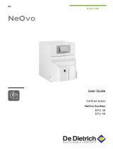
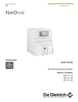
Operating and
Maintenance Manual
EFU 2.7-Twin
EFU 3.8
EFU 5.6
0235221; 0235231; 0235241

2

3
Contents
1. Introduction ................................................................................................ 4
2. Description ................................................................................................. 5
3. Technical data ............................................................................................ 5
4. Safety .......................................................................................................... 7
5. Operation.................................................................................................. 10
6. Maintenance ............................................................................................. 13

4
1. Introduction
This operating and maintenance manual is designed to help you
become familiar with your converter and enable you to maintain it
and use it for its intended purpose.
The safety instructions and warnings provided in this manual will
help avoid hazards, reduce repair and downtime costs and increase
the reliability and operational readiness of your converter. Follow
these instructions precisely.
This operating and maintenance manual must always be kept at
the implementation site of the converter and be available to the
operator.
Turn to your Weber MT dealer if you require any additional
information.
Found on the last page of this manual is a QR code. Scan it to
acquire the current contact addresses of all Weber MT branches.
You can obtain the current spare parts list of the machine in the
WeberMT Service App or use the link below:
https://www.webermt.com/DE/deu/ersatzteillistenspare-parts-efu/efu/

5
2. Description
This device is an electronic frequency converter for operation with
high-frequency internal vibrators made by Weber MT.
3. Technical data
EFU 2.7-Twin EFU 3.8 EFU 5.6
Weight
Operating weight kg 30 34 39
Connection
Input voltage V 230 400 400
Power input A 16 13 15
Frequency Hz 50 50 50
Output
Output voltage V 48 / 250 48 48
Output current A 32 / 7 48 75
Output power kVA 2.7 4.0 6.0
Output frequency Hz 200 200 200
Power outlets 2 / 1 3 3
Degree of protection IP 44 IP 44 IP 44
Sound pressure level Lpa Below 70 dB (A)

6
1
3
2
4
5
Note down this information so that you can recreate the rating plate should the plate be lost.
1 Designation 2 Type
.................................................... ...................................................
3 Serial no. 4 Year of construction
.................................................... ....................................................
5 Weight
...................................................

7
4. Safety
General All safety instructions must be read and complied with, as non-
compliance will result in
- Danger to life and limb of the user,
- Impairments to the machine or other property.
In addition to the operating manual, the accident-prevention regulations
in the country where the appliance is used must be complied with.
Intended use The converter should only be used in technically faultless condition, as
intended, in a safety-conscious and hazard-conscious manner, and in
compliance with the instructions in the operating manual.
Malfunctions that impair safety must be eliminated without delay.
The converter is designed exclusively for the following operations:
- Connection and operation of Weber MT high-frequency internal
vibrators of the types IV, IV-D (EFU 1.3) or IV-S
(only EFU 2.7-Twin)
Non-intended use Unless used as intended, the device involves a risk of personal injury
and property damage. The device is expressly not suitable for:
- Use as a step.
- The connection of other devices.
The responsibility for any damage arising from non-intended use falls
on the owner / operator rather than the manufacturer.
Requirements on the
operator
This converter may only be operated by suitable operators who are 18
years or older. They must be instructed on how to operate the device
by the owner or by the owner's assigned personnel and need to be
physically and mentally t to use the device.
Personal
protective equipment
Personal protective equipment consisting of
- Protective goggles
- Hearing protection
- Work shoes or boots with toe guard
must be worn during operation and the execution of maintenance on the
device.
Spare parts, changes
and conversions
Changes and conversions are prohibited unless made with original
Weber MT spare parts. If the machine is modied with other
accessories without the approval of Weber MT, the manufacturer will not
assume liability for any resulting personal injury or property damage.
All maintenance and repairs must be carried out with original Weber MT
spare parts. Untested spare parts may aect the reliability and safety of
the machine.

8
Prior to commissioning The device must not be operated unless all safety devices
(mechanical and electrical) are complete and operational.
To prevent overload and other types of damage, the device may
only be connected to the mains supply specied on the rating plate.
The mains supply must be equipped with a grounding conductor.
If the device tips over or slides around, plugs or individual cables
on the inside of the device may detach. There is a risk of short
circuits. The device must therefore be set up in a stable position and
secured against tipping over or sliding around.
Damage to the cable may compromise the insulation of individual
wires. There is a risk of short circuits. The cable must therefore be
protected against mechanical damage.
Do not lay the cable across sharp edges and keep it protected
against heat and oil.
There is a risk of short circuits if moisture enters the interior of the
device. Therefore, do not expose the device to rain and do not
operate the device in a wet or moist environment.
The device must not be operated in an explosive atmosphere.
Check if the control and safety devices are eective to prevent
damage from electric current or equipment that was switched on
inadvertently.
During operation To keep connected equipment from being switched on inadvertently,
the device must not be switched on or o by inserting or removing
the connector plug into and from the power outlet.
As individual wires on the inside of the plug or the device may
detach, the cable must not be used for pulling out the power plug.
Check the cable for mechanical damage (e.g. cuts) regularly during
operation in order to prevent short circuits or electric shocks.
To avoid accidents of any kind, the device must not be used unless
all protective xtures are operational. If detecting defects on the
protective xtures, stop operation immediately, disconnect the
device from the power supply by pulling the plug out of the power
outlet and notify your supervisor.

9
Maintenance / repair The device does not require any maintenance.
Should repairs become necessary, have them performed by trained
professionals.
In case electronic components are aected, the work may only be
performed by a trained electrician.
To ensure safe operation following any necessary repairs, all
protective xtures must be checked.
This includes a check of whether current can pass through the
grounding conductor.
Transport When loading the device with a crane, use lifting gear with sucient
bearing capacity.
When transporting the device on a vehicle, secure the device
against tipping over, rolling away and sliding around.
Inspection Have converters inspected for operationally safe status in
accordance with the regulations applicable in the country of use at
least every 6 months or more frequently if necessary.
Safety instructions and
warnings
A variety of safety instructions and warnings are used throughout
this operating manual.
The following explains the meaning of signal words and symbols.
ATTENTION warns of the dan-
ger of material damage.
CAUTION warns of the danger
of slight injury.
WARNING warns of a danger
that may lead to death or seri-
ous injury.
DANGER warns of a danger
that will lead to death or serious
injury unless avoided.
ATTENTION
CAUTION
WARNING
DANGER
The information symbol provides supplemental
information on the operation of the machine and points to
complementary technical information.

10
5. Operation
Preparing the machine for
initial use
Remove all packaging material.
Check all components for visible damage. Do not start the device
if detecting visible damage. Contact the responsible dealer.
Check if the shipment of the device and its components is
complete.
Set up the device at its place of use.

11
2
1
3
4
Operating positions on the device
1 Main switch
2 Device switch “Start”
3 Power outlet
4 Power plug

12
Connection to the mains
supply
Before connecting the device to the mains supply, perform a
visual inspection to verify that the device is undamaged.
Make sure the mains voltage corresponds to the voltage and
frequency specied on the rating plate.
WARNING! Danger from an electric shock caused by parts
that have become live due to a fault.
Do not connect the converter to a mains supply that is not
protected by an RCD type B residual current circuit breaker.
Insert the plug into a suitable power outlet.
Connection of
internal vibrators Danger of material damage from overload! The power input of the
connected internal vibrators must not exceed the specied output
current of the converter!
ATTENTION
Connect the device to the corresponding power outlet of the
converter (green).
Commissioning of the
converter
CAUTION
Danger of material damage and slight injury if the connected internal
vibrators are switched on inadvertently.
Before connecting the converter, always make sure that the
connected internal vibrators have been switched o at their own
device switch.
Set the main switch (1) to “I” (ON).
Switch the converter on at the device switch “Start” (2).
The converter is switched on, and the equipment can be
connected.
Shutdown of the
converter
Start by shutting down the connected internal vibrators to keep
the internal vibrators from being switched on inadvertently during
the next operation of the converter.
Switch the converter o at the device switch “Start” (2).
Set the main switch to “0” (OFF).
The converter is switched o. The power plug can be pulled out
of the power outlet.
ATTENTION! Danger of material damage! Never pull on the
cable to remove a plug.

13
6. Maintenance
The device requires next to no maintenance. No maintenance is
needed except for a daily visual inspection of the device and cable
for exterior damage.
If the visual inspection reveals damage on the device, the damage
must be corrected by trained professionals. If in doubt, contact the
responsible Weber MT partner.

14
20019315 EFU 2,7 Twin
Q1
Hauptschalter
U1
Netzfilter
U2
Frequenzumrichter
T1
Trenntransformator
L1 N
0I 1 3
4
2
L1
L1 LOAD
LINE
N
NPE
U V W RH
STF
230V
48V
X1
250V/200Hz
P24
L1 N
X2
48V/200Hz
X3
48V/200Hz
Circuit diagram EFU 2.7-Twin

15
20019314 EFU 3,8 / 5,6
Q1
Hauptschalter
U1
Netzfilter
U2
Frequenzumrichter
T1
Trenntransformator
L1
0 I 1
2
L1
L1LOAD
LINE
U V W RL
SE
400V/200Hz
48V/200Hz
PC
X2
48V/200Hz
X3
48V/200Hz
X1
48V/200Hz
3 5
6
4
L1 L2 L3
L2
L2
L3
L3
RUN STF
0 I
Q2
Start
Circuit diagram EFU 3.8 / 5.6

16
facebook.com/WeberMT
youtube.com/MyWeberMT
Weber Maschinentechnik GmbH
Im Boden 5-8, 10 · 57334 Bad Laasphe · Germany
Phone +49 2754 398 0 · Fax +49 2754 398 101
[email protected] · www.webermt.de
085105202-104 / EFU 3,8;5,6_2021-10
Original operating manual
/