
3. Mounting bore for sensor
For even cavity wall, mount the sensor at right angles to the
cavity. In hardened tool steel erode, mill or grind the H7-bore.
Note the centering and the alignment. Clean the threads free
of chips.
• Clean the mounting bore and the threads free of chips
• This sensor cannot be adapted to the contour!
Quick Start Installation
Mold cavity pressure sensor for RTM method with ø9 mm
Front
Type 6161AA… (–18,5 pC/bar, 200 bar, 200 °C)
1. General Information
• Sensor diameter ø9 mm should not be machined
• The sensor front must be clean and without any
notches
• Use only the mounting socket recommended
• Do not pull on the cable to extract the sensor from
the bore
6161AA_002-627e-06.16
Contents
1. General Information
2. Critical points of the mounting bore
3. Mounting bore
4. Cable routing and Connector
5. Mounting the sensor
6. Cable and plug connection
7. Mounting the nameplate
8. Functional test
9. Service and Repairs
Foreword
Information in this document is subject to change without
notice. Kistler reserves the right to change or improve its
products and make changes in the content without obligati-
on to notify any person or organization of such changes or
improvements.
© 2013...2016, Kistler Group. All rights reserved.
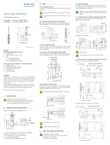
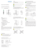
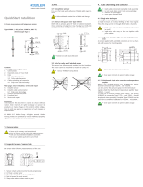
1. The bearing surface is flat and at right angles
2. The bevel protects the O-ring during mounting
3. Sensor centering in H7-bore is concentric to the mounting
thread M12x1
4. Sharp edge reduces the mark on the component
The Type 6161AA... sensor has a diaphragm front. The front of
this sensor should not be machined under any circumstances.
Machining the front will damage the sensor.
Machining the sensor front shall invalidate all liability and
warranty claims!
2. Critical points of the mounting bore
The following points in the bore must be watched:
9
10,8
M12x
1
613,1
24
A
3
2
4
1
0,01 A
A
3
2
4
1
0,01 A
20
12
6
0,4
30°
9 H7( -0,015
-0 )
11 H7( -0,015
-0 )
M12x1
16
4. Cable routing and Connector
• Fixed cables simplify the installation of tools
• Do not route the cables around hot runner cartridges
• Break sharp edges
• Cover open channels
Mill cable runner and recess for the mounting plate.
• Cover open channels with sheet metal
7. Mounting the nameplate
Rivet the nameplate to the side of the tool or mount it using
four M2.5 screws.
5. Mounting the Sensor
• All sensor bores and threads must be clean
• Radial curves in the channels and at transitions pre-
vent damage to the cables
Place the sensor in the bore. Remove the fastening nuts from
the connector. Thread the Type 1387sp mounting socket
over the cable and place it at the end of the sensor. Screw
the sensor in the mounting threads. Hand-tighten with a 3-5
N∙m torque.
• Hand-tighten with a 3-5 N.m torque
• Use the Type 1387sp extraction tool
8. Functional test
Once the tool is assembled completely, check the insulation
of the sensor in the assembled state.
• Make sure all connectors are dry
• Use Type 1003 cleaning spray
8.1 Insulation check
Check the insulation of the sensor using the Type 5495A
insulation tester. Insulation resistance >1013 Ω.
8.2 Check the function of the sensor
Test the sensitivity of the installed sensor using Test Set
Type 5495.
Approximate measured sensitivity value:
–14 … –21 pC.
• For the functional test the adptor Type 55124493
must be mounted on the Test pin. The diaphrame
will be destroyed when testing without the adaptor.
16
0,015+
9 H7
12
0,4
20
0
M12x1
6*
60°
11 H7 +0,018
0
* adjust
Kistler Group
Eulachstrasse 22
8408 Winterthur, Schweiz
Tel. +41 52 224 11 11
Fax +41 52 224 14 14
info@kistler.com www.kistler.com
6. Cable and plug connection
• Once again check that there are no sharp edges in the
cable bore and cable channel
• Provide all open channels with cover plates
• Fasten the covers and cover the connector
Fasten the plugs to the mounting plate using nuts. Mount
the mounting plate on the tool. Fasten the plug cover with a
screw and push it onto the connector.
9. Service and Repairs
9.1 Dismounting the sensor
Unscrew the plug from the mounting plate, thread the
Type 1387sp mounting socket over the cable and pull it
over the sensor end. Unscrew the sensor from the bore.
9.2 Cable repair/Replacement
The replaceable coaxial cable cannot be repaired at the
customer‘s end by soldering, because the cable insulation
no longer exists. However, if the cable is damaged, it can be
replaced by the customer. For this, the following is required:
• Mounting socket Type 1300A49
• Replacement cable Type 55066174
9.3 Repairs at Kistler
Factory repairs at Kistler are arranged by the local sales office.
Information: www.kistler.com
9.4 Disposal Instructions for Electrical and Electronic
Equipment
Do not discard old electronic instruments in
municipal trash. For disposal at end of life,
please return this product to an authorized
local electronic waste disposal service or
contact the nearest Kistler Instrument sales
office for return instructions.
• Do not hit the sensor front
6161AA_002-627e-06.16 ©2013...2016, Kistler Group
-
 1
1
Kistler 6161AA5 Quick start guide
- Category
- Signal cables
- Type
- Quick start guide
Ask a question and I''ll find the answer in the document
Finding information in a document is now easier with AI
Related papers
-
 Kistler 4001A502FA2,0 Quick start guide
-
 Kistler 6165AA Quick start guide
-
 Kistler 6183D Quick start guide
-
 Kistler 6185AAG1 Quick start guide
-
 Kistler 6167A Quick start guide
-
 Kistler 9239B Quick start guide
-
 Kistler 6185AAG1 Quick start guide
-
 Kistler 6190CA5 Quick start guide
-
 Kistler 6178C Quick start guide
-
 Kistler 6189ASP Quick start guide


