Page is loading ...

UN DERH OOD A I R COMPRE SSORS
UN DERH OOD A I R COMPRE SSORS
UN DERH OOD A I R COMPRE SSORS
UN DERH OOD A I R COMPRE SSORS
UN DERH OOD A I R COMPRE SSORS
UN DERH OOD A I R COMPRE SSORS
UN DERH OOD A I R COMPRE SSORS
UN DERH OOD A I R COMPRE SSORS
UN DERH OOD A I R COMPRE SSORS
UN DERH OOD A I R COMPRE SSORS
UN DERH OOD A I R COMPRE SSORS
UN DERH OOD A I R COMPRE SSORS
UN DERH OOD A I R COMPRE SSORS
UN DERH OOD A I R COMPRE SSORS
THE BENCHMARK IN INNOVATION
1333 KIPP ROAD NANAIMO B.C. V9X
1R3
TEL: (250)-740-3200
www. .comunderhoodair
Visit us at...
UN DERHOOD AI R COM PRESSORS
UN DERH OOD AI R COM PRESSORS
Installation Manual
For The
2003 DODGE 5.9L CUMMINS
24 VALVE TURBO DIESEL
System # V900071

Installation Manual Document Number: 1930022
VR70 Underhood Air Compressor
System Number V900071
Application
2003 Dodge 5.9L 24 Valve Cummins Diesel
Publication Date
Current: Revised by T. W. Mitchner, 26 August 2003
Notice
Manuals and products are subject to change without notice.
Registered Trademarks
VR70, VMAC and Throttle Commander are registered trademarks of VMAC.
Dodge and Magnum are registered trademarks of Daimler-Chrysler AG.
Loctite, Klean N’ Prime, 242 and PST are registered trademarks of Loctite Corporation.
Nylok is a registered trademark of Nylok Fastener Corporation.
Copyright 2003
The contents of this manual may not be reproduced in any form without express, written permission.

Page 1
Contents
PART 1 GENERAL INFORMATION ............................................................................................. 3
1.1 INTRODUCTION............................................................................................................................ 5
1.2 INSTALLATION STEPS................................................................................................................... 5
1.3 TERMS AND SYMBOLS ................................................................................................................. 5
1.4 INSTALLATION NOTES.................................................................................................................. 5
1.5 SYSTEM IDENTIFICATION NUMBER PLATE.................................................................................... 6
1.6 WARRANTY................................................................................................................................. 7
1.7 ORDERING PARTS ........................................................................................................................ 7
1.8 TOOL REQUIREMENTS.................................................................................................................. 7
1.9 SPECIAL INSTALLATION NOTES.................................................................................................... 8
1.10 CHANGES AND IMPROVEMENTS ................................................................................................. 8
PART 2 PREPARING FOR INSTALLATION............................................................................... 9
2.1 PREPARATION FOR INSTALLATION............................................................................................. 11
PART 3 INSTALLING THE AIR TANK AND LINES ............................................................... 17
3.1 INSTALLING THE TANK MOUNT BRACKETS ................................................................................ 19
3.2 INSTALLING THE C-CLAMPS ...................................................................................................... 19
3.3 CONNECTING THE AIR AND OIL LINES TO THE TANK .................................................................. 22
PART 4 INSTALLING THE COMPRESSOR AND OIL COOLER ......................................... 23
4.1 INSTALLING THE CRANK PULLEY ............................................................................................... 25
4.2 INSTALLING THE COOLER .......................................................................................................... 25
4.3 INSTALLING THE MAIN BRACKET ............................................................................................... 27
4.4 INSTALLING THE COMPRESSOR .................................................................................................. 28
4.5 ATTACHING THE LINES TO THE COMPRESSOR ............................................................................ 29
4.6 COMPLETING THE INSTALLATION .............................................................................................. 32
4.7 ADDING OIL TO THE SYSTEM ..................................................................................................... 36
PART 5 INSTALLING THE CONTROL COMPONENTS ........................................................ 37
5.1 INSTALLING THE THROTTLE CONTROLLER................................................................................. 39
5.2 CONTROL BOX INSTALLATION ................................................................................................... 43
5.3 CONNECTING THE WIRING HARNESSES ...................................................................................... 44
5.4 TESTING THE SAFETY CIRCUIT ................................................................................................... 49
PART 6 ILLUSTRATED PARTS LIST......................................................................................... 53
WARRANTY..................................................................................................................................... 59

Page 2

DOCUMENT #1930022
Page 3
Part 1
General Information
System # V900071
2003 Dodge 5.9L 24 Valve Cummins Diesel
UNDERHOOD AIR COMPRESSORS

Page 4

Page 5
1.1 Introduction
This book provides installation instructions for the VMAC underhood air compressor installation kit.
1.2 Installation steps
The installation procedure in this manual has four main steps:
• Preparing for Installation
• Installing the Air Tank and Lines
• Installing the Compressor and Oil Cooler
• Installing the Control Components
1.3 Terms and symbols
This manual uses the following terms and symbols:
• OEM - Original Equipment Manufacturer
• HHCS - Hex Head Cap Screw (also called a hex bolt)
• SHCS - Socket Head Cap Screw (also called an Allen head bolt)
This symbol indicates that there is additional information or special
emphasis on a specific procedure.
This symbol indicates that there is a possibility of personal injury or damage
to the equipment if the indicated warning is not followed.
1.4 Installation notes
1. It is important that you complete all the installation steps before operating the system.
2. Follow all safety precautions for underhood mechanical work.
3. Use Loctite 242 or equivalent on all engine-mounted fasteners.
4. All hoses, tubes and wires which are re-routed or shifted during installation must be secured
so that they do not contact excessively hot areas or sharp edges. Where possible, follow the
routing suggestions in this manual.
5. These installation instructions are intended as a general guide. In some instances, due to
variations in vehicle manufacture or if prior modifications have been made to the vehicle, it
may be necessary to carry out grinding, bending or rearranging operations for correct fit.
These operations must follow sound, standard shop practices.
6. Left and right definitions in this manual are determined when sitting in the driver’s seat,
facing forward.

Page 6
All fasteners must be of the correct size and torqued according to specifications (Table 1).
Torque specifications are in foot pounds (ft-lb) and are only applicable when Loctite is used. If
the threads are dry, add 20% to the torque values.
STANDARD GRADE 8 NATIONAL COARSE THREAD
Size 1/4 5/16 3/8 7/16 1/2 9/16 5/8 3/4
Foot-pounds 9 18 35 55 80 110 170 280
STANDARD GRADE 8 NATIONAL FINE THREAD
Size 3/8 7/16 1/2 5/8 3/4
Foot-pounds 40 60 90 180 320
METRIC CLASS 10.9
Size M8 M10 M12 M14 M16
Foot-pounds 19 41 69 104 174
Table 1- Torque Specifications
Hose diameter Color coded label Part number prefix
1/4” Yellow 173
5/16” Orange 174
1/2” & 5/8” Blue 175 & 176
3/4” & 1” Green 177 & 178
Table 2- Hose color codes
Table 2 above illustrates the color code used by VMAC to define the different hose diameters.
Check that system hoses are all tight before running the system. Refer to setup procedure in the
Owner’s Manual before attempting to run this air system.
Different frame designations will affect the tank mounting position. You may have to move the tank
rearward from the standard position on your application. If you must move the tank, the lines may be
too short. If this is the case, measure the hose shortfall and order a “Hose Extender Kit”, P/N
(A410XXX). The last three digits in the P/N indicate the length of the extension, for example,
A410055 is a 55-inch hose extender kit.
1.5 System identification number plate
The System Identification Number Plate included with the kit must be attached to the vehicle at
the time of installation. Locate the plate as shown below. Mark and drill two holes using a 7/64”
drill bit. Secure the plate in position using the supplied #6 pan head, self-tapping screws.

Page 7
1.6 Warranty
The VMAC warranty form is located at the back of this manual. This warranty form must be
completed and mailed or faxed to VMAC at the time of installation for any subsequent warranty
claim to be considered valid.
1.7 Ordering parts
To order parts, contact your nearest VMAC dealer.
Please quote the VMAC part number, the description and the quantity.
1.8 Tool requirements
The following tools are required for compressor installation:
• 1/2” drive metric socket set
• 8 – 24 mm metric wrench set
• 1/2” drive SAE socket set
• 7/16” – 1 1/4” SAE wrench set
• Allen key sets – metric and SAE
• mechanic’s screwdriver set
• nut drivers – 5/16- 3/8 inch
• 1/2-inch drill with assorted bits up to 1/2-inch
• Fan clutch wrench set (KD Tools 3472 or equivalent).
System ID number plate location

Page 8
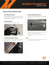
VR70 Tank
A
uxiliary Receiver
Auxiliary tank valve
Install the line as high as
possible, NOT on the
bottom of the tank
• hacksaw or zip wheel suitable for cutting metal
The following tools are required for throttle component installation:
• small soldering gun or soldering pen
• wire cutters
• wire strippers
• crimping tool
• digital multi-meter – preferably with a frequency (Hz) setting
• small jeweler’s screwdriver set for the adjustment of the throttle control
1.9 Special installation notes
If you intend to use an auxiliary air receiver with this system you must observe
the following installation procedure. Failure to observe this procedure will
result in damage to the system.
1. The line from the VR70 tank to the auxiliary air receiver must have an auxiliary tank valve
installed to prevent blowback from the auxiliary tank and to prevent moisture from entering
the VR70 tank.
2. The line to the auxiliary tank must not be installed in the bottom of the tank, but must be
installed as high as possible to prevent water from clogging the line.
1.10 Changes and improvements
These products and documents are subject to changes or improvements without notice.

DOCUMENT #1930022
Page 9
Part 2
Preparing for Installation
System # V900071
2003 Dodge 5.9L 24 Valve Cummins Diesel
UNDERHOOD AIR COMPRESSORS

Page 10

Page 11
2.1 Preparation for installation
1. Remove both negative battery terminals (Figure 1 & 2).
2. Drain the coolant.
3. Disconnect the electrical connector from the mass air sensor (Figure 3).
4. Disconnect the air cleaner assembly and remove it (Figure 4).
Figure 2 – Driver side negative battery terminalFigure 1 – Passenger side negative battery terminal
Figure 3 – Mass air sensor electrical connectio
n
Figure 4 – Remove air cleaner trunking

Page 12
5. Remove the upper radiator hose (Figure 7).
6. Disconnect the fan clutch wire and cut it loose from its OEM mounting clips so it can be re-
positioned later and remove the lower edge of the fan shroud (Figure 8).
Figure 6 – Removal of the air cleaner unit
Figure 5 – Remove the front air cleaner securing bolt
Figure 7 – Removal of the upper radiator hose Figure 8 – Fan clutch wire connecto
r

Page 13
7. Remove all fasteners form the fan shroud and coolant expansion tank (Figure 9 & 10).
8. Remove both intercooler tubes (Figure 11 & 12).
9. Slip the fan shroud out of the truck in unison with the coolant expansion tank
(Figure 13 & 14).
10. Remove the fan using the appropriate wrenches. (KD Tools Fan Clutch Wrench set 3472 or
equivalent).
Figure 10 – Lower fan shroud fastener detail
Driver side fastene
r
Passenger side fastene
r
Figure 9 – Lower fan shroud fastener detail
Figure 12 – Driver side intercooler tube
Figure 11 – Passenger side intercooler tube

Page 14
11. Remove the OEM belt (Figure 16).
Figure 13 – Coolant expansion tank removal Figu
r
e 14 – Upper fan shroud removal
Figure 15 – Lifting out the fan Figure 16 – Removing the OEM belt
Ease the OEM tensione
r

Page 15
12. Remove the upper alternator mount and lifting lug (Figures 18 & 19).
13. Disconnect all wires from the alternator and remove the lower alternator mount bolt and set
the alternator aside (Figure 20).
14. Remove the crank pulley and scrape off the entire clear coat from the front face that the bolt
heads pull against (Figure 21).
15. Remove the 1/2-inch NPT plug from the cylinder head (Figure 22).
Figure 17 – Remove the uppe
r
alternator bolt Figure 18 – Remove the upper alternator mount
Figure 19 – Remove the engine lifting lug Figure 20 – Remove the lower alternator mount bolt

Page 16
It is important to remove all surface clear coat on the face of the crank pulley
(figure 21).
Figure 21 – Scraping the crank pulley face Figure 22 – Remove the cylinder head plug

DOCUMENT #1920022
Page 17
Part 3
Installing the Air Tank and
Lines
System #V900071
2003 Dodge 5.9L 24 Valve Cummins Diesel
UNDERHOOD AIR COMPRESSORS

Page 18
/