Page is loading ...

Installation Manual
For The
System #V900061
UNDERHOOD AIR COMPRESSOR
2001 GENERAL MOTORS
2500HD - 3500
DURAMAX DIESEL
TEL: 250-740-3200
FAX: 250-740-3201
TOLL FREE: 800-738-8622
1333 KIPP ROAD, NANAIMO, B.C. V9X 1R3
Document 1900686

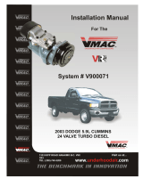
Installation Manual 1900686
VR70 Underhood Air Compressor
System Number V900061
Application: 2001 General Motors HD2500 - 3500 with a Duramax diesel engine
Publication Date: Revised by S. Large, August / 2002
Origination Documents: 1900686 - Manual Document
1900686a - General information
1900686b -Preparing for installation
1900686c - Installing the air tank and lines
1900686d -Installing the cooler and main bracket
1900686e - Installing the control unit
1900868f - Illustrated parts list
1900030 - Warranty Registration
Registered Trademarks:
VR70, VMAC and Throttle Commander are registered trademarks of VMAC.
HD2500, 3500 and Duramax are registered trademarks of General Motors Corporation.
Loctite, Prime N’ Clean, 242 and PST are registered trademarks of Loctite Corporation.
Nylok is a registered trademark of Nylok Fastener Corporation.
Notice:
Manuals and products are subject to change without notice.
Copyright 2002
The contents of this manual may not be reproduced in any form without the express written
permission of VMAC

Contents
GENERAL INFORMATION ................................................................................................. 3
INTRODUCTION ........................................................................................................................ 5
INSTALLATION NOTES ................................................................................................................ 5
ORDERING PARTS ...................................................................................................................... 6
WARRANTY ............................................................................................................................. 6
CHANGES AND IMPROVEMENTS ................................................................................................... 7
TOOL REQUIREMENTS ............................................................................................................... 8
PART 1: PREPARING FOR INSTALLATION ................................................................... 9
PART 2: INSTALLING THE TANK AND LINES............................................................ 17
2.1 INSTALLING THE CABLES AND STRAPS ................................................................................ 19
2.2 INSTALLING THE C-CLAMPS .............................................................................................. 20
2.3 INSTALLING THE L-BRACKETS .......................................................................................... 20
2.4 INSTALLING THE P-CLIPS ................................................................................................. 21
2.5 INSTALLING THE TANK .................................................................................................... 22
2.6 ATTACHING LINES TO THE TANK ...................................................................................... 23
PART 3: INSTALLING THE COOLER AND MAIN BRACKET .................................. 25
3.1 INSTALLING THE COOLER ................................................................................................. 27
3.2 INSTALLING THE VR70 CRANK PULLEY ............................................................................ 27
3.3 INSTALLING THE RADIATOR AND HOSES .............................................................................. 28
3.4 INSTALLING THE MAIN BRACKET AND COMPRESSOR ............................................................. 29
3.5 INSTALLING OTHER COMPONENTS ..................................................................................... 31
3.6 CONNECTING THE REMAINING HOSES ................................................................................ 36
3.7 COMPLETING THE INSTALLATION ..................................................................................... 37
PART 4: INSTALLING THE CONTROL COMPONENTS ............................................ 41
4.1 INSTALLING THE CONTROL UNIT ....................................................................................... 44
4.2 INSTALLING THE SWITCHING BOX ...................................................................................... 45
4.3 INSTALLING THE THROTTLE COMMANDER ......................................................................... 45
4.4 CONNECTING DRIVE DISABLE CIRCUIT (DDC) ...................................................................... 47
4.5 CONNECTING THE WIRE HARNESSES .................................................................................. 50
PART 5: ILLUSTRATED PARTS LIST ............................................................................. 53
WARRANTY REGISTRATION.......................................................................................... 59
1

2

General Information
System #V900061
2001 GENERAL MOTORS
2500HD - 3500
DURAMAX DIESEL
UNDERHOOD AIR COMPRESSOR
3
Document 1900686

4

This symbol indicates that there is additional information or special emphasis
on a specific procedure.
This symbol indicates that there is a possibility of personal injury or damage to
the equipment if the indicated warning is not followed.
General Information
Introduction
This book provides installation instructions for the VR70 Underhood Air Compressor. The
information in this book should be read completely before attempting installation.
Installation steps
The installation procedures are divided into the following main steps:
Part 1: Preparing for installation
Part 2: Installing the tank and lines
Part 3: Installing the cooler and main bracket
Part 4: Installing the control components
Terms and symbols
This manual uses the following terms and symbols:
•OEM - Original Equipment Manufacturer
•HHCS - Hex Head Cap Screw (also called a hex bolt)
•SHCS - Socket Head Cap Screw (also called an Allen head bolt)
Installation notes
1. It is important that you complete all the installation steps before operating the system.
2. Follow all safety precautions for under-hood mechanical work.
3. Use Loctite 242 or equivalent on all engine-mounted fasteners.
4. All hoses, tubes and wires which are re-routed or shifted during installation must be secured
so that they do not contact excessively hot areas or sharp edges. Where possible, follow
the routing suggestions in this manual.
5
WARNING
!
NOTE

5. These installation instructions are intended as a general guide. In some instances, due to
variations in vehicle manufacture or if prior modifications have been made to the vehicle, it
may be necessary to carry out grinding, bending or rearranging operations for correct fit.
These operations must follow sound, standard shop practices.
6. Left and right definitions in this manual are determined when sitting in the driver’s seat,
facing forward.
7. All fasteners must be of the correct size and torqued according to the specifications shown
below. Torque specifications are in foot pounds (ft-lb). Always use manufacturers torque
values for OEM fasteners.
The above fastener torque values are applicable when Loctite is used.
Ordering parts
To order parts, contact your VMAC dealer.
Please quote the VMAC part number, the description and the quantity.
Warranty
The VMAC warranty form is located at the back of this manual. This warranty form must be
completed and mailed or faxed to VMAC at the time of installation for any subsequent warranty
claim to be considered valid.
The enclosed System Identification Number Plate must be attached to the vehicle at the time of
installation. Locate the plate as shown in Figure 1. Drill the two hole locations using a 7/64” drill
bit. Attach the plate with the two supplied #6 pan head self tapping screws.
This plate provides information, which allows VMAC to assist in customer inquiries and
the ordering of parts. It is important that this plate is affixed to the vehicle.
6
NOTE
STANDARD GRADE 8 NATIONAL COARSE THREAD
Size 1/4 5/16 3/8 7/16 1/2 9/16 5/8 3/4
Foot-pounds 9 18 35 55 80 110 170 280
STANDARD GRADE 8 NATIONAL FINE THREAD
Size 3/8 7/16 1/2 5/8 3/4
Foot-pounds 40 60 90 180 320
METRIC CLASS 10.9
Size M8 M10 M12 M14 M16
Foot-pounds 19 41 69 104 174

Figure 1 Location of System Identification Number Plate
7
Special installation notes
If you intend to use an auxiliary air receiver with this system you must observe the following
installation procedure (Figure 2) . Failure to observe this procedure will result in damage to the
system.
1. The line from the VR70 tank to the auxiliary air receiver must have a one-way check valve
installed to prevent blowback from the auxiliary tank and to prevent moisture from entering
the VR70 tank.
2. The line to the auxiliary tank must not be installed in the bottom of the tank, but must be
installed as high as possible to prevent water from clogging the line.
Figure 2
VR70 Tank
Auxiliary Receiver
One-way check valve
Install the line as high as
possible, NOT on the
bottom of the tank
Changes and improvements
These products and documents are subject to changes or improvements without notice.

8
Tool Requirements
List of tools required for compressor installation
•OEM crankshaft locking tool (GM - #J-44643) or equivalent VMAC crankshaft locking
tool (Part # 5900010) .
• VMAC crankshaft pin extraction tool (Part # 5900076) .
•1/2” drive metric socket set.
•1/2” drive SAE socket set.
•Allen key sets – metric and SAE.
•Mechanic’s screwdriver set.
•Nut drivers – 5/16- 3/8 inch.
•1/2-inch drill with assorted bits up to 1/2-inch.
•Hacksaw or zip wheel suitable for cutting metal.
List of tools required for throttle component installation
•Small soldering gun/ Soldering pen.
•Wire cutters.
•Wire strippers.
•Crimping tool.
•Digital multimeter – preferably with a frequency (Hz) setting.
•Very small Jeweler’s screwdriver set for the adjustment of the throttle control.

9
Part 1
Preparing for Installation
System #V900061
2001 GENERAL MOTORS
2500HD - 3500
DURAMAX DIESEL
UNDERHOOD AIR COMPRESSOR
Document 1900686

10

11
1. Disconnect the positive and ground cables
from the batteries.
2. Remove the plastic cowling from the top
of the engine.
3. Drain the coolant into a suitable container.
4. Disconnect the top radiator hose from the
radiator and move out of the way.
5. Remove the bolts holding the upper fan
shroud and remove the engine control
module (ECM) and cover from the
driver’s side of the upper fan shroud
(Figure 2).
Do not disconnect the ECM wire
harness, just move the module over
to one side.
6. Remove the upper fan shroud (Figure 3).
7. Disconnect the hoses from the coolant
tank and the heater return hose which is
attached to the lower radiator hose.
8. Remove the lower radiator hoses.
9. Remove the fan using a pin wrench in the
water pump pulley and a fan clutch nut
wrench (as per manufacturers
instructions).
10. Remove the air duct from air cleaner to
engine (Figure 1).
Figure 1
Figure 2
Figure 3
ECM
NOTE

12
11. Remove the plastic inner fender liner on
the passenger’s side. This is an optional
technique to give greater accessability.
12. Disconnect the MAF sensor wire from the
air cleaner and then remove the air cleaner
assembly.
13. Remove the 6mm OEM bolts locating the
air cleaner base mounting plate, then
remove the two 6mm bolts locating the air
cleaner support bracket to the front
upright (Fig. 4).
14. Disconnect the hoses from the passenger
side intercooler tube and remove the tube
and hoses.
15. Disconnect the level sensor wire and
remove the coolant expansion tank and
radiator bleed hose.
16. Disconnect the wiring plugs from the
crank position sensor and the cam sensor
on the front of the engine (Figure 6).
17. Remove the 8 mm cap screw holding the
sensor wire harness clip to the front lower
engine block.
18. Disconnect the two ground wires (from
the same loom) from the lower engine
block.
19. Remove the engine breather canister and
the hose attached to the lower engine
block.
Figure 4
Figure 5
Figure 6
Fuel bleed valve studs
8mm Bolt for breather tube clamp
CAM Position Sensor
Crank Position Sensor

13
20. Remove the 8mm bolt from the cast
alternator mounting bracket that holds the
breather tube and wire harness (Figure 5).
21. Cut the tie wrap holding the loom and
breather tube together.
22. Remove the two (2) nuts from the fuel
bleed valve (Figure 5).
23. Disconnect both fuel inlet and outlet
banjos from the fuel module (Figure 7).
24. Remove the fuel management module on
the top of the right engine bank and move
it up and out of the way. Keep all the
rubber washers, plastic spacers and
mounting bolts (Figure 7).
25. Remove the short fuel outlet hose and
angled banjo fitting from the engine-side
fuel rail. Remove the banjo from the
hose and discard the hose.
26. Disconnect the dipstick tube from the fuel
management module mount bracket, then
remove and discard the complete fuel
module and dipstick mount bracket
(Figure. 7).
27. Remove the alternator wiring and locating
bolts and remove the alternator. Do not
damage the air conditioning line.
Figure 7
Figure 8
Figure 9

14
28. Unclip the top of the wire harness plastic
channel attached to the engine fuel rail,
carefully lift out the wiring and cut the ties
locating module end of the channel. Also
remove the lower plastic wire harness
channel (Figure 8).
29. Remove and discard the metal coolant
tube from the heater to the lower radiator
hose.
30. Remove the OEM 8 rib drive belt.
31. Remove the rock guard from under the
front of the vehicle. Keep the bolts.
32. Remove the 18 mm crank pulley bolt
using the recommended OEM crankshaft
locking tool (Figure 11). GM Part #. J-
44643.
33. Remove the crank pulley
34. Using the VMAC crankshaft pin
extraction tool (part # 5900076), remove
the OEM crankshaft pin. An Illustration
of this tool is shown on page 15. Please
see also (Figures 13, 14 and 15).
35. Remove the two (2) OEM belt idlers and
the belt tensioner. Keep the bolts (Figure
11).
36. Remove the bolts holding the cast
aluminum alternator mounting bracket and
remove and discard the casting (Figure 5).
Figure 10
Figure 11
Figure 12
First Bend

15
37. Locate the first bend on the passenger-
side air conditioning line from the firewall
end. At this location, carefully bend the
tube downward approximately 3-1/2
inches (Figure 12).
Figure 13
Figure 14
OEM pin before
extraction
VMAC Crankshaft Pin Extraction Tool
Pinch Bolt
Slider mechanism
Figure 15

16

17
Part 2
Installing the Tank and
Lines
System #V900061
2001 GENERAL MOTORS
2500HD - 3500
DURAMAX DIESEL
UNDERHOOD AIR COMPRESSOR
Document 1900636

18
/