Page is loading ...

INSTALLATION SUPPLEMENT
Nissan, Toyota, Honda, Ram, Jeep
& GM CarbonPro bed
Extang Corporation
5400 S. State Road, Ann Arbor, MI 48108
800-877-2588 © Extang Corporation, 2021 Part# 31855036-30 Rev. 10-22-21
Nissan Titan 2016+ WITHOUT the Utili-Track System Channel ......................................................1
Nissan Titan 2016+ WITH the Utili-Track System Channel ..............................................................2
Toyota Tacoma 2016+ ..........................................................................................................................3
Toyota Tundra 2016+ ............................................................................................................................4
Honda Ridgeline 2017+ ..................................................................................................................... 5-6
RamBox DT 2019+ .............................................................................................................................. 7-8
Jeep Gladiator ..................................................................................................................................9-12
GM CarbonPro bed ........................................................................................................................13-14
READ THIS FIRST
This supplement replaces steps 3-7 in the main install sheet for
the vehicles listed below.
Read this guide before proceeding with
the main installation.

INSTALLATION SUPPLEMENT
This supplement replaces steps 3-7 in the main
install sheet for the vehicles noted.
Read this guide
before proceeding with the installation.
Tighten the clamp bolts, the front, middle and rear. The lower adjustment bolt and rubber stops are used to
support and level the rail.
3 4
1
5
2
Extang Corporation
5400 S. State Road, Ann Arbor, MI 48108
800-877-2588 © Extang Corporation, 2021 Part# 31855036-30 Rev. 10-22-21Page 1
Nissan Titan 2016+ WITHOUT the
Utili-Track System Channel
Slide the outer
clamp halves into
the tapered slot
of the bed rails.
Center the middle clamp between the
front and rear clamp locations.
Position the front and rear clamps as close to the ends as possible.
They should be less that 12” from the end of the rail.
It is important that all areas
where the bed cover mounts
are clean and free of debris prior
to installing.
Place the bed rail onto the truck cap. Assemble the inner clamp halves to the
outer clamps positioned on the rail. Adjust the clamp positions as necessary.
Thread the bolt through a washer and into the clamp half.
When tightening, push
down on the rails, as
well as in towards the
bed rail and forward
toward the bulkhead.
Loosen the lock nut and
adjust the bolt in or out.
Re-tighten the lock nut.
Torque the clamp bolts
to 13.6 Nm (120 in-lb)
DO NOT torque the adjustment bolt,
only tighten to position it to the bed
wall. The lock nut needs only to be snug.
Repeat all of the steps for both sides. Return to the standard installation instructions. Follow step 2 for the bulkhead seal,
then skip to step 8.
Lock
nut
Rubber
stop
Adjustment
bolt
Part# 31855036-30 Rev. 10-22-21

INSTALLATION SUPPLEMENT
This supplement replaces steps 3-7 in the main
install sheet for the vehicles noted.
Read this guide
before proceeding with the installation.
Place the rail onto the truck bed rail, match the two clamp halves,
thread a bolt through a washer into the inner clamp half.
Repeat all of the steps
for both sides. Return to
the standard installation
instructions. Follow step 2
for the bulkhead seal, then
skip to step 8.
When tightening
push down on the
rails, as well as in
towards the bed
rail and forward
toward the
bulkhead.
3
54
1
2
Nissan Titan 2016+ WITH the
Utili-Track System Channel
Slide the back half of the clamp directly into the vehicle tracks. The clamp halves install with the grooves facing out. Align the
clampasshownwiththelargegroovedendrst.NOTE: If reusing the factory tie-downs be sure to install them intermittently with
the bed cover clamp halves.
NOTE: Some drop-in liners may require
trimminginthecornerstottherail.
Torque the clamp bolts
to 13.6 Nm (120 in-lb)
It is important that all areas
where the bed cover mounts
are clean and free of debris prior
to installing.
Slide the outer
clamp halves into
the tapered slot
of the bed rails.
Center the middle clamp between the
front and rear clamp locations.
Position the front and rear clamps as close to the ends as possible.
They should be less that 12” from the end of the rail.
Tighten the clamp
bolts, the front,
middle and rear.
Extang Corporation
5400 S. State Road, Ann Arbor, MI 48108
800-877-2588 © Extang Corporation, 2021 Part# 31855036-30 Rev. 10-22-21Page 2

INSTALLATION SUPPLEMENT
This supplement replaces steps 3-7 in the main
install sheet for the vehicles noted.
Read this guide
before proceeding with the installation.
4
76
1
2 3
Toyota Tacoma 2016+
5
It is important that all areas
where the bed cover mounts
are clean and free of debris prior
to installing.
Remove the factory cab header rail. Remove the
backing from the foam seals, and adhere a seal
to both sides of the header rail. Reassemble the
header rail to the truck, tighten the fasteners to
7.5Nm, (66.5 in-lb)
Remove the factory cargo rail and fasteners.
Retain both for later reinstallation.
Mount the cover rail and brackets to the truck
bed using the factory cargo rail fasteners and
into the cargo rail mounting holes.
Mount the factory cargo rail to the
lower holes of the cover brackets
using the provided small fasteners.
Repeat all of the steps for both sides. Return to the
standard installation instructions. Follow step 2 for
the bulkhead seal, then skip to step 8.
Make sure the cover rail is
pushed forward, tight against
the bulkhead. Tighten the
fasteners.
Align and slide the cover rail brackets into the slot in the rail.
The brackets will be spaced to match the factory cargo rail holes.
Torque the fasteners
to 7.5 Nm (66.5 in-lb)
Torque the fasteners
to 7.5 Nm (66.5 in-lb)
Extang Corporation
5400 S. State Road, Ann Arbor, MI 48108
800-877-2588 © Extang Corporation, 2021 Part# 31855036-30 Rev. 10-22-21Page 3

INSTALLATION SUPPLEMENT
This supplement replaces steps 3-7 in the main
install sheet for the vehicles noted.
Read this guide
before proceeding with the installation.
1
2
Toyota Tundra 2016+
3
4
5
It is important that all areas
where the bed cover mounts
are clean and free of debris prior
to installing.
Align and slide the cover rail brackets into the
slot in the rail. The brackets will be spaced to
match the factory cargo rail holes.
Mount the factory cargo rail to the lower
holes of the cover brackets using the
provided small fasteners.
Mount the cover rail and brackets to the truck bed using the factory
cargo rail fasteners and into the cargo rail mounting holes.
Make sure the cover rail is pushed forward, tight against the bulkhead. Tighten the fasteners.
Remove the factory cargo rails
and fasteners. Retain both for
later reinstallation.
Torque the fasteners
to 7.5 Nm (66.5 in-lb)
Torque the fasteners
to 7.5 Nm (66.5 in-lb)
Repeat all of the steps for both sides.
Return to the standard installation
instructions. Follow step 2 for the
bulkhead seal, then skip to step 8.
Extang Corporation
5400 S. State Road, Ann Arbor, MI 48108
800-877-2588 © Extang Corporation, 2021 Part# 31855036-30 Rev. 10-22-21Page 4

Front
accessory
mount
bracket
Rear
accessory
mount Tap
plates
Mounting
bolts
Cab
mounting
bracket
Rear
mounting
bracket
INSTALLATION SUPPLEMENT
This supplement replaces steps 3-7 in the main
install sheet for the vehicles noted.
Read this guide
before proceeding with the installation.
1
2
3 4
Honda Ridgeline 2017+
Page 1 of 2
5 6
It is important that all areas where the bed cover mounts
are clean and free of debris prior to installing.
Assemble the cab
and rear mounting
brackets to the
accessory mount
brackets slide them
into the rail channels.
Remove the upper factory cleats and fasteners. Keep the
fasteners for reuse, the cleats will not be reinstalled.
Thread the factory fasteners through the cover rail
mounting brackets and into the factory holes where the
cleats where mounted.
With all four fasteners in place, start at the front and push
down and forward on the rail while tightening. Push down
on the rear of the rail while tightening the fasteners.
Slide the mounting brackets to the front and to the rear.
Set the cover rail onto the truck bed rail and align the
bracket holes with the factory cleat mounting holes.
Torque the fasteners
to 7.5 Nm (66.5 in-lb)
Torque the fasteners
to 7.5 Nm (66.5 in-lb)
Repeat all of the steps
for both sides. Return to
the standard installation
instructions. Follow step
2 for the bulkhead seal,
then skip to step 8.
Mark the
holes for
the drain
tube using
the
provided
template.
Insert the
end of the
drain hose
into the
drain hole.
Attach the hoses
onto the drain rails.
Drill 19mm (3/4”) diameter
holes in both front corners.
Extang Corporation
5400 S. State Road, Ann Arbor, MI 48108
800-877-2588 © Extang Corporation, 2021 Part# 31855036-30 Rev. 10-22-21Page 5

Drill Template
Driver/Left side
Drill Template
Passenger/Right side
Mark the holes for the
drain tube using this template.
Mark the holes for the
drain tube using this template.
19mm (3/4”) diameter hole
When copying
or printing,
this dimension
should be
6 3/4” or
171.45mm.
19mm (3/4”) diameter hole
INSTALLATION SUPPLEMENT
This supplement replaces steps 3-7 in the main
install sheet for the vehicles noted.
Read this guide
before proceeding with the installation.
Honda Ridgeline 2017+
Page 2 of 2
Extang Corporation
5400 S. State Road, Ann Arbor, MI 48108
800-877-2588 © Extang Corporation, 2021 Part# 31855036-30 Rev. 10-22-21Page 6

INSTALLATION SUPPLEMENT
This supplement replaces steps 3-7 in the main
install sheet for the vehicles noted.
Read this guide
before proceeding with the installation.
1 2
3
5
4
RamBox DT 2019+
Page 1 of 2
It is important that all areas
where the bed cover mounts
are clean and free of debris prior
to installing.
Remove the factory
accessory rails.
ContinuetoplacetheatD-seal
across the back end cap.
NOTE:Intherailinstallation,thefoldingcoverproprod(A)andproprodbracket(B)willconictwiththe
factory tie-down cleats (C & D). If a tie-down cleat is needed forward in the bed it can remain in the front (C).
Otherwise the tie-down cleats need to be removed for rail installation.
With the seals in place on both sides, reinstall the factory accessory rails.
Trimming may
be required.
Torque the fasteners
to 7.5 Nm (66.5 in-lb)
Extang Corporation
5400 S. State Road, Ann Arbor, MI 48108
800-877-2588 © Extang Corporation, 2021 Part# 31855036-30 Rev. 10-22-21Page 7
A B
C
D
Applytherollofatsealalongthebedtobe
between the bed and the factory accessory rail. Make sure the seal extends
beyond the ends of the accessory rail, from the bulkhead through to the back
corner trim cap. Do this for both sides.

1
2
4
3
INSTALLATION SUPPLEMENT
This supplement replaces steps 3-7 in the main
install sheet for the vehicles noted.
Read this guide
before proceeding with the installation.
Repeat all of the steps for both sides. Return to the standard installation instructions. Follow step 2 for the bulkhead seal, then
skip to step 8.
10
11
6 7
8 9
RamBox DT 2019+
Page 2 of 2
Remove the cargo rail end caps and
tie-down cleats as noted in step 5.
Slide the hard folding cover rails forward until the foam seal (H, from Step 7)
contacts the bulkhead (I).
Adhere the ribbed D-seal in the end cap corner to span the mounting rail caps and rear trim panel. Add one to each side.
Trimming the seal may be required.
Replace the tie-down cleats and
the cargo rail end caps, both sides.
NOTE:
A soapy water
solution will help
with assembly.
Extang Corporation
5400 S. State Road, Ann Arbor, MI 48108
800-877-2588 © Extang Corporation, 2021 Part# 31855036-30 Rev. 10-22-21Page 8
E
F
G
H
I
Slide the hard folding cover rails into
the top of the cargo rails with the slotted bracket (E) in front and on
the inside of the truck bed. The hard folding cover rails use the rounded
clip ends (F) to spring into the cargo rail groove (G).

2
1
34
56
78
9
10
11
12
A
B
7654
3
11
10
9
8
1
Fig. 2
0.18”,
4.8mm
2.6”, 66.7mm
2.6”, 66.7mm
2.5”,
63.5mm
2.5”,
63.5mm
BD
C
A
WITHOUT WELD NUTWITH WELD NUT
INSTALLATION SUPPLEMENT
This supplement replaces steps 3-7 in the main
install sheet for the vehicles noted.
Read this guide
before proceeding with the installation.
Jeep Gladiator
Page 1 of 4
1
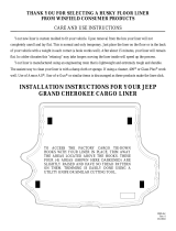
Drop-in Liner Trimming
If the truck has a drop-in bedliner, the top corners at
the bulkhead, and the top corners of the tailgate liner
need to be trimmed to allow for the bed cover rails.
CAUTION: Move the bedliner away from the
truck sheet metal, or remove the liner from the
truck so that the truck bed is not damaged.
Locate the necessary cuts by starting with
the top left corner edge of the liner 1,
then measure a distance of 0.18”, 4.8mm,
outwards to establish point A.Therstcut
is down from A 2.5”, 63.5mm, to point B.
The next cut is from point A, inwards
horizontally 2.6”, 66.7mm, to point C.
Cut from point C to D,thennishwitha
cut from B to D.
The cut is done on the passenger side as a
mirror image, Figure 2.
TOOLS RECOMMENDED
l 7/8” (22mm) drill bit & drill
l T-50 Torx drive
l T-30 Torx drive
l T-45 Torx drive
l 1/8” Hex head wrench
l Utility knife or cutting tool
PARTS INCLUDED
IN YOUR KIT
1x Passenger side cover rail
1x Driver side cover rail
VEHICLES WITH A WELD NUT
2x Well nuts
2x Washers
2x Hex button head screws
2x T-50 Torx head bolts
4x Spacers
4x M6 screws with washers
VEHICLES WITHOUT A WELD NUT
4x M6 screws with washers
2x Bulkhead brackets
2x
M8 bolts T-45
2x M8 bolts T-50 with washers
Extang Corporation
5400 S. State Road, Ann Arbor, MI 48108
800-877-2588 © Extang Corporation, 2021 Part# 31855036-30 Rev. 10-22-21Page 9
It is important that all areas where the bed cover
mounts are clean and free of debris prior to installing.
VEHICLES WITHOUT
A WELD NUT
VEHICLES WITH
A WELD NUT
A
C G
B
I
J
K
D H HF J KE I
A
C
B
D
H
H
F
J
E
I
G
K
C
D
F
E
G
H H

0.375”, 9.5mm
0.875”,
22.2mm
INSTALLATION SUPPLEMENT
This supplement replaces steps 3-7 in the main
install sheet for the vehicles noted.
Read this guide
before proceeding with the installation.
5
3
4
Jeep Gladiator
Page 2 of 4
NOTE: It is important that all areas where the
bed cover mounts are clean and free of debris
prior to installing.
Holes are necessary in the drop-in
bedliner for the bed cover rail drain tubes.
A 7/8”,[0.875”, (22mm)], diameter hole
needstobecenteredontherstribfrom
the edge. The hole will be 2.875”, 73mm,
upfromtheoor.The hole is cut on both
sides, as a mirror image.
If the bed rail caps are not trimmed at the
tailgate section, cut using the scribed lines as a
guide to expose the area shown. Perform this
operation on both sides of the pickup box.
Extang Corporation
5400 S. State Road, Ann Arbor, MI 48108
800-877-2588 © Extang Corporation, 2021 Part# 31855036-30 Rev. 10-22-21Page 10
Identify the bulkhead hole
congurationofyourvehicle
located near the cab.
Vehicles WITH a weld nut Vehicles WITHOUT a weld nut
Weld nut VIN BX210534
and OLDER vehicles
NO weld nut VIN BX210535
and NEWER vehicles
Weld nut or threaded hole
No weld nut or open hole
Open hole
Hexagonal hole
Weld nut or threaded hole
No weld nut or open hole
Open hole
Hexagonal hole
2
CAUTION: Move the tailgate liner away from the
truck sheet metal, or remove the liner from the truck
so that the truck bed is not damaged.
Locate the necessary cuts for the tailgate liner by
starting with the outside corner of the liner, measure
a distance of 0.375”, 9.5mm inward, then 0.875”,
22.2mm, down. The cut is done on both sides,
as a mirror image.
Centered on
the first rib.
Diameter =
7/8” [0.875”,
22mm]
2.875”,
73mm

INSTALLATION SUPPLEMENT
This supplement replaces steps 3-7 in the main
install sheet for the vehicles noted.
Read this guide
before proceeding with the installation.
Tighten the M6 screw & washers (H), on both driver and
passenger’s sides. While tightening the screws, push
down on the tailgate end of the rail.
Jeep Gladiator
Page 3 of 4
6 7 8
9
11
10
12
For vehicles with a spray-in bedliner,
the threaded area in the bulkhead
must be cleared of liner material.
On the passenger side cover rail
(A), thread the button head screw
(E) through the washer (D), through
the top hole in the bracket and into
the well nut (C). Repeat on the
driver’s side cover rail (B).
Note: Assemble just until contact is made,
do NOT tighten the well nut.
Insert the M6 screw & washer (H)
into one of the rear rail mounting
holes on the passenger side cover
rail (A). Slide a spacer (G) onto the
threaded portion of the screw (H).
Repeat for the second rear mounting
hole, then repeat on the driver side
cover rail (B).
Place the cover rail (A & B) onto the bed rail and slide it
forward, using the well nut (C) as a guide into the
bulkhead opening.
Thread the T-50 Torx head bolt (F) through the bottom hole
of the cover rail bracket, and tighten it to 17.5 Nm/12.9 ft/
lbs on both sides. Snug up the upper button head screw (E)
in the well nut (C).
At the tailgate, thread the M6 screw & washers (H) from
step 8, into the threaded inserts in the bed wall. Tighten
with a T-30 Torx wrench. Leave the bolts
loose until the cab bolts have been
installed and tightened.
Extang Corporation
5400 S. State Road, Ann Arbor, MI 48108
800-877-2588 © Extang Corporation, 2021 Part# 31855036-30 Rev. 10-22-21Page 11
WITH WELD NUT - STEPS 6 -12
Make sure all of the steps are completed for both sides of the bed.
Return to the standard installation instructions.

INSTALLATION SUPPLEMENT
This supplement replaces steps 3-7 in the main
install sheet for the vehicles noted.
Read this guide
before proceeding with the installation.
Make sure all of the steps are
completed for both sides of the
bed. Return to the standard
installation instructions.
Jeep Gladiator
Page 4 of 4
13
14
15
17
16
18
Insert the M6 screw & washer (H)
into one of the rear rail mounting
holes on the passenger side cover
rail (A). Slide a spacer (G) onto the
threaded portion of the screw (H).
Repeat for the second rear mount-
ing hole, then repeat on the driver
side cover rail (B).
Place the passenger side cover rail (A) onto the bed rail and slide it forward up
against the bulkhead. Lower the bulkhead bracket (I) between the truck cab and
the front of the bulkhead so that the threads of the bulkhead bracket (I) align with
the two open holes in the bulkhead.
Thread the T-50 bolts with washers (K) into
the lower hole of the bed rail and the bulkhead
bracket (I). Do NOT fully tighten the bolts.
Repeat on the driver’s side cover rail (B).
At the tailgate, thread the screws (H) installed into the rail
from step 13, into the threaded inserts in the bed wall.
Tighten with T-30 Torx wrench. Leave the bolts loose
until the screws for the bulkhead have
been tightened. Repeat on
the driver’s side.
Tighten the screw and washers (H) at the tailgate with the
T-30 Torx wrench. While tightening the bolts, push down
on the rear/tailgate end of the rail.
Tighten the screws on the
driver’s side.
Install the small T-45 bolts (J) into the upper hole of the bed
rail and the bulkhead bracket (I). Tighten both bolts (J & K),
repeat on the driver’s side.
Extang Corporation
5400 S. State Road, Ann Arbor, MI 48108
800-877-2588 © Extang Corporation, 2021 Part# 31855036-30 Rev. 10-22-21Page 12
WITHOUT WELD NUT - STEPS 13-18

Install 5 U- nuts into each of the slots, and on both sides of the truck bed.
Cab end
Tailgate end
driver side
INSTALLATION SUPPLEMENT
This supplement replaces steps 3-7 in the main
install sheet for the vehicles noted.
Read this guide
before proceeding with the installation.
1
2
GM CarbonPro bed
Page 1 of 2
TOOLS REQUIRED
l 10mm open end wrench
l Drill
l 7mm, (9/32”) drill bit
l 22.3mm (7/8”) drill bit
l Utility knife or cutting tool
TOOLS RECOMMENDED
l Trim stick
PARTS INCLUDED
IN YOUR KIT
1x Driver side cover rail
1x Passenger side cover rail
10x U-nuts
10x M6 bolt
2x Bed cap hole guide
2x Drain hoses (from main kit)
U-nut installation - InserttheU-nuts(C)bypryingtheplastictruckbedcapawayfromthetruckbed.TheU-nutstunderneath
the plastic truck bed cap and onto the carbon side (Fig. 1). Make sure that the U-nut is aligned with the bed rail hole as shown
in Fig. 2. Repeat for the passenger side.
Drill mounting holes - Slide the bed cap hole guide (E) onto the edge of the plastic truck bed cap and in between the cap and the
bed(Fig.3).AligntheguidesothatitsbacktsintotheholeoftheU-nut(Fig.4).Drilla7mm,(9/32”)holethroughtheplastictruck
bed cap using the bed cap hole guide (Fig. 5). The back of the guide will prevent the drill from hitting the truck bed. Repeat this for
every U-nut location on both sides of the truck bed.
The plastic truck bed
cap is removed for
illustration purposes.
NOTE: A trim stick (not shown) is useful
for prying out the plastic truck bed cap.
The plastic truck
bed cap is shown
as a dotted line
so that the
placement of the
U-nut underneath
can be shown.
Fig. 1
Fig. 2
Fig. 3
Fig. 4
Fig. 5
Extang Corporation
5400 S. State Road, Ann Arbor, MI 48108
800-877-2588 © Extang Corporation, 2021 Part# 31855036-30 Rev. 10-22-21Page 13
It is important that all areas where the bed cover mounts
are clean and free of debris prior to installing.
A
C
B
D
E
F
A
B
C
D
E
CD E

INSTALLATION SUPPLEMENT
This supplement replaces steps 3-7 in the main
install sheet for the vehicles noted.
Read this guide
before proceeding with the installation.
3
4
GM CarbonPro bed
Page 2 of 2
5
Drill drain hole & install drain tube
Drill a 22.3mm, (7/8”) hole through the
truck bed liner at the center of the existing
circular divot as shown. Drill the hole on
both the driver and passenger side.
Insert the cut end of one half of the drain hose (F)
into the drilled hole in the bed. Push the hose into
the hole with the diagonal cut as shown for the
driver side. Slide the collared end of the hose onto
the cover rail drain. Install the other half of the
hose on the passenger side in the same manner.
The drain hoses
are included in the
standard install kit.
A single drain hose
is cut in half for this
install, make the
cut at a 45 degree
angle.
Repeat all of the steps for both sides. Return to the standard installation instructions. Follow step 2 for the bulkhead seal, then
skip to step 8.
Fig. 6
Fig. 7
Be careful to only drill
through the outer liner.
Extang Corporation
5400 S. State Road, Ann Arbor, MI 48108
800-877-2588 © Extang Corporation, 2021 Part# 31855036-30 Rev. 10-22-21Page 14
Rail installation - Thread the M6 bolts (D) through the drilled holes and into the U-nuts until
they are spaced approximately 3.18mm (1/8”) from the bed cap (Fig. 6). Place the driver side cover rail (A) by aligning the slots
onto each of the bolts (Fig. 7). Push down on the cover rail to help the seals set to the truck bed cap and tighten the bolts with the
10mm open end wrench. Repeat the steps for the passenger side cover rail (B).
/