Page is loading ...

Enable-IT 865XC PRO
Gigabit Coax PoE Extender Kit
Quickstart Guide
Professional Grade Networking
All Rights Reserved © 1982 - 2024 Enable-IT™, Inc.

INSTALLING THE 865XC PRO COAX POE EXTENDER KIT
We highly recommend that you perform a quick out of the box test to ensure the working order of your
Enable-IT 865XC PRO Gigabit Coax PoE Extender units prior to installing. This will also serve to
familiarize you with how easy the process should be. Follow the steps below to perform the Out Of the
Box Test.
Step 1 - Attach the 60W 56V DC Gigabit PoE Injector and power adapter to the local 865X PRO unit and
power up the unit. The Power LEDs will indicate the injector and 865X PRO unit is receiving power.
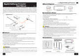
Step 2 - Connect the 865X PRO Coax Interlink ports together as shown by the green line connecting the
ports in the diagram above.
The Green LED Sync indicator on each of the 865X PRO units will blink as they see each other and
then go solid once they are synched together.
!
Left side LEDs
Mode – Yellow Solid LED (LED Off = CO unit, LED On = CPE unit)
Sync – Green slow to fast flicker LED on power up – indicates negotiation of a link
– Green solid LED indicates link established and rapid pulse is traffic.
Power – Green Solid LED indicates the unit is receiving 12V power.!
!
Right side LEDs
Act – Yellow LED
Off = No device attached or detected.
On = Solid, indicates the presence of local LAN.
Blinking = Indicates the presence of local LAN traffic.
The Green Sync LEDs will start flickering slowly and then fast as the units talk to each other. After a
few seconds you should see a solid Green Interlink Sync LED on each unit to confirm a link is
established. This confirms basic proper operation of the units.!
!
Step 3 - Next for a more detailed test and to confirm your PoE Equipment works with the 865XC PRO, connect
your Ethernet LAN to the 865XC PRO CO unit LAN ports and the remote device/s to the 865XC PRO
CPE LAN ports and test connectivity. The Green Interlink Sync LED will pulse rapidly as it detects
traffic.
All Rights Reserved © 1982 - 2024 Enable-IT™, Inc. Page of 2 5
The Enable-IT 865XC PRO Gigabit Coax PoE Extenders have a distance restriction of 3,000ft (915m)
over 75 Ohm rated RG6 cabling from device extension to device extension.!
!
Therefore a site survey of the wiring and installation planning are highly recommended.!
For highest performance use 75 Ohm rated RG6 cabling for the interlink wiring.

Performing the On-Site Installation
After removing the Enable-IT 865XC PRO Gigabit Coax PoE Extender Kit from the box, and
performing the Out Of The Box Testing (OOTBT), all that remains to install the unit on-site is to
mount the unit, build the interconnect wiring, add voice lines if needed, and attach the LAN
device cabling with the provided Ethernet Patch cords.
Building the 865XC PRO Interlink Wiring
The most important aspect of the installation is the correct wiring of the Interlink cabling.
The 865XC PRO Interlink port (Coax BNC) carries this 1-pair signaling over 75 Ohm rated RG6
cabling and is used as the transport for gigabit transport.
For all wiring you will need to crimp a Coax BNC head to each end of the contiguous wire run.
We recommend using a category rated twisted pair cable as it is optimized for high throughput
frequencies isolated from cross-talk noise. Insert the completed BNC Coax ends into the
865XC PRO Interlink port on each 865XC PRO unit (CO and CPE).
Cabling Devices to The Enable-IT 865XC PRO Extended Ethernet Kit
Attach your remote LAN device to the 865XC PRO CPE unit LAN ports with Ethernet patch cord
provided. Attach your local LAN to the 865XC PRO CO LAN ports with Ethernet patch cord
provided. Attach the power adapters to both 865XC PRO units.
Attach your local Interlink cabling end to the 865XC PRO CO unit Interlink port – Then do the
same for the remote end and plug into the 865XC PRO CPE unit Interlink port. The Sync LED’s
will flicker in a sequence talking to each other until they go solid. Your equipment should now
be powered up and functioning. LED indicators will provide visual operational status of the
865XC PRO units.
Troubleshooting
First examine the backbone wiring pair and make sure you have solid connections. The Interlink
Sync LED will be lit solid Green with rapid pulsing on each 865XC PRO unit to show proper
connection and pairing. If the Interlink Sync LED Link is flashing slow to fast and never goes solid….
Then follow the steps below:
1) Make sure your wiring is straight through end to end coax.
2) Check for a firm connection of the RJ-45 connections in each 865XC PRO unit, and
power is applied to the 865XC PRO CO & CPE units.
3) You can easily isolate any issue by performing an Out Of The Box Test (OOTBT). This
test will confirm the correct working order of your Enable-IT 865XC PRO Gigabit Coax
All Rights Reserved © 1982 - 2024 Enable-IT™, Inc. Page of 3 5
865XC PRO CPE
865XC PRO CO
Coax Interlink Cabling up to 3,000 feet / 915m

PoE Extender Kit. This will point to a possible issue with your long distance Interlink
wiring being affected by possible outside interference.
865X PRO Remote unit DIP Switch Settings
•Switch 1: ON - 865X PRO remote unit
PoE On – Down / On Position - Default
PoE Off – Up / Off Position
•Switch 2: ON - 865X PRO remote unit 4-Pair output
PoE 2-Pair – Up / Off Position
PoE 4-Pair – Down / On Position - Default
•Switch 3: Not Used
•Switch 4: Not Used
TECHNICAL SUPPORT
Online Technical Services
The Enable-IT Support Portal is available 24/7 to open a ticket or check the status of one. Please use
this support website as your first source for help as it contains an on-line knowledge base of articles,
documentation, FAQ's and other problem-solving resources. This web-based support resource
provides the quickest solution to the most common technical support issues.
Returning Products for Warranty Repair
Enable-IT warrants to the original purchaser of this described Product ("you" or the "End User") that,
for the limited lifetime period commencing on the date the Product was purchased (the “Warranty
Period"), the Product will be substantially free from defects in materials and workmanship under
normal use and conditions. Lifetime Warranty details here: https://warranty.enableit.com
This warranty does not apply to Products, which are resold as used, repaired or reconditioned.
Electrical or water damage is not covered under this warranty, extended warranties or
Advanced Replacement Program (AREP).
In order to obtain an authorized RMA approval, the End User must complete the required information
online located at https://support.enableit.com If you have questions or difficulty completing this
information you may contact the Customer Care Team at 888-309-0910 between the hours of 7:00
a.m. and 4:00 p.m. Pacific Time(PST).
Returning Products for Refund
Enable-IT, Inc. offers a generous 45-Day refund on a single Ethernet Extender Kit only, and is
subject to a 20% Restocking Fee. Shipments without a valid or authorized RMA number, or
sent to our corporate Las Vegas address, can be refused and / or billed for additional shipping.
CONTACT US
Sales and Customer Care:
Toll Free US and Canada 888 309-0910
Other International +1 702 924-0402
All Rights Reserved © 1982 - 2024 Enable-IT™, Inc. Page of 4 5

/