Page is loading ...

Made in Switzerland
60 Years of Innovation
®
Operating Instructions
Swiss Precision since 1954
Design Patent Pending

© 2015 Proceq SA 2
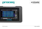
APundit Touchscreen
BBattery
CPundit Pulse Echo Transducer*
DPundit Pulse Echo Cable*
EPundit Pulse Echo Contact Tester*
FPower Supply
GUSB Cable
HDVD with Software
IDocumentation*
JCarrying Strap
KCalibrated Tape*
*Part of the “Pundit Pulse Echo Trans-
ducer” package (Part No. 327 40 130)
A
F
J
G
B
HI
Scope of Delivery
DE
C
K


© 2015 Proceq SA 4
Table of Contents
1. Safety and Liability ...................................................... 5
1.1 General Information ........................................................... 5
1.2 Liability ...............................................................................5
1.3 Safety Instructions ............................................................5
1.4 Correct Usage ...................................................................5
2. Technical Specifications .............................................. 6
3. Operation ...................................................................... 7
3.1 Getting Started ..................................................................7
3.2 Main Menu .........................................................................8
3.3 Settings ..............................................................................8
3.4 Measurement Screen ......................................................10
3.5 Measurement Modes ......................................................11
3.6 Measuring with Pundit PL-200PE ...................................15
4. Explorer ...................................................................... 16
4.1 Analysis of B-Scans ........................................................17
5. Ordering Information ................................................. 17
5.1 Units .................................................................................17
5.2 Transducers .....................................................................17
5.3 Accessories .....................................................................18
6. Maintenance and Support ......................................... 18
6.1 Maintenance ....................................................................18
6.2 Support Concept ............................................................18
6.3 Warranty Information .......................................................18
6.4 Disposal ...........................................................................18
7. PL-Link Software ....................................................... 19
7.1 Starting PL-Link ............................................................... 19
7.2 Viewing the Data ............................................................19
7.3 Adjusting the Settings .....................................................21
7.4 Analysis of B-Scans ........................................................21
7.5 Exporting Data ................................................................. 21
7.6 Further Functions ............................................................22

© 2015 Proceq SA 5
1. Safety and Liability
1.1 General Information
This manual contains important information on the safety, use and main-
tenance of the Pundit PL-200PE. Read through the manual carefully be-
fore the first use of the instrument. Keep the manual in a safe place for
future reference.
1.2 Liability
Our “General Terms and Conditions of Sales and Delivery” apply in all
cases. Warranty and liability claims arising from personal injury and dam-
age to property cannot be upheld if they are due to one or more of the
following causes:
• Failure to use the instrument in accordance with its designated use as
described in this manual.
• Incorrect performance check for operation and maintenance of the in-
strument and its components.
• Failure to adhere to the sections of the manual dealing with the per-
formance check, operation and maintenance of the instrument and its
components.
• Unauthorised modifications to the instrument and its components.
• Serious damage resulting from the effects of foreign bodies, accidents,
vandalism and force majeure
All information contained in this documentation is presented in good faith
and believed to be correct. Proceq SA makes no warranties and excludes
all liability as to the completeness and/or accuracy of the information.
1.3 Safety Instructions
The equipment is not allowed to be operated by children or anyone under
the influence of alcohol, drugs or pharmaceutical preparations. Anyone
who is not familiar with this manual must be supervised when using the
equipment.
• Carry out the stipulated maintenance properly and at the correct time.
• Following completion of the maintenance tasks, perform a functional
check.
1.4 Correct Usage
• The instrument is only to be used for its designated purpose as de-
scribe herein.
• Replace faulty components only with original replacement parts from
Proceq.
• Accessories should only be installed or connected to the instrument
if they are expressly authorized by Proceq. If other accessories are
installed or connected to the instrument then Proceq will accept no
liability and the product guarantee is forfeit.
Table of Contents

6 © 2015 Proceq SA
2. Technical Specifications
Instrument
Range 0.1 – 7930 μs
Resolution 0.1 μs (< 793 μs), 1 μs (> 793 μs)
Display 7” colour display 800x480 pixels
Pulse Voltage UPV 100 Vpp – 450 Vpp
Pulse Voltage UPE 100 Vpp - 400 Vpp
Receiver Gain 1x – 10’000x (0 – 80dB) [11 steps]
Receiver Sensitivity 10 μV
Receiver Input Impedance 7 kΩ
Pulse Echo Range 0.1 – 1200 μs
Transducer Frequency 50 kHz
Aperture Size 2x25 cm2
Bandwidth 20 – 500 kHz
Memory Internal 8 GB Flash memory
Regional Settings Metric and imperial units and
multi-language supported
Battery Lithium Polymer, 3.6 V, 14.0 Ah
Mains 9 V – 15 V / 2.0 A
Weight About 1525 g (incl. Battery)
Dimensions 250 x 162 x 62 mm
Operating Temperature 0°C – 30°C (Charging*, running instrument)
0°C – 40°C (Charging*, instrument is off)
-10°C – 50°C (Non-charging)
Humidity < 95 % RH, non condensing
IP Classification IP54
Standards and Directives CE certification
Battery Lifetime > 8h (in standard operating mode)
Pollution Degree 2
Installation Category 2
*charging equipment is for indoor use only (no IP classification)
Power Supply
Model HK-AH-120A500-DH
Input 100-240 V / 1.6 A / 50/60 Hz
Output 12 V DC / 5 A
Max. Altitude 2’500 m above sea level
Humidity < 95%
Operating Temperature 0°C - 40°C
Environment Indoor use only
Pollution Degree 2
Installation Category 2
Table of Contents

© 2015 Proceq SA 7
3. Operation
The information provided in this manual covers the Pulse Echo application
only. The Pundit PL-200PE also supports all functionality provided by the
Pundit PL-200. It is necessary to purchase the BNC adapter cable (Part
No. 327 01 049) for operation with standard P-wave transducers. A full
listing of the standard transducers can be found on the Proceq website.
The Pundit PL-200 operating manual is provided on the product DVD.
3.1 Getting Started
Battery Installation
To install the Battery (B) into the Pundit Touchscreen (A), lift the stand as
shown. Insert the battery and fasten in place with the screw.
There are three status LEDs 1 (see page page 3). The middle LED is
red while charging and turns to green when fully charged. The other LEDs
are application specific.
NOTE! Only use the power supply provided.
• A complete charge requires <9h (Instrument not operating).
• Charging time is much longer if the instrument is in use.
• An optional quick charger (Part No. 327 01 053) can be used to charge
a spare battery outside of the instrument. In this case it takes <4h for
a complete charge.
Energy Saving
Energy saving, time to dim display and time to turn off display, may be
programmed as desired under System/Power settings.
Connecting the transducer
(D)
Connect the Pulse Echo Transducer (C) to the Pundit Touchscreen (A)
using the Pulse Echo Cable (D).
USB Host:
Connect a mouse, keyboard or USB stick.
USB Host
USB Device
Ethernet
Power Supply
USB Device:
Connect application specific probes and PC.
Ethernet:
Connection for firmware upgrades.
Power Supply:
Connect the power supply through this connection.
Table of Contents

8 © 2015 Proceq SA
Buttons
Lift the protective visor.
The upper right of the screen there are three buttons 2 (see page 3).
Power On/Off – Press to power on. Press and hold to power off.
Soft Key – Switches in and out of full screen view or opens a pdf
document such as the operating instructions.
Back Button – Returns to previous screen.
3.2 Main Menu
On start up the main menu is displayed. All functions may be accessed
directly via the touchscreen. Return to the previous menu by pressing the
back button or the return icon (arrow) at the top left of the touchscreen.
Measurement: Application specific measurement screen.
Settings: For application specific settings.
Explorer: File manager functionality for reviewing measure-
ments saved on the instrument.
System: For system settings, eg. language, display options,
power saving
Information: For device information and operating instructions.
Exit: Power Off.
3.3 Settings
Scroll up and down the screen by dragging your finger up or down the
screen. The current setting is displayed on the right hand side. Tap on an
item to adjust it.
Transducer
Connected Transducer
If a Pulse Echo Transducer is connected this will be recognized automatically.
Test Transducer
Each individual dry contact transducer can be tested for correct func-
tionality.
The graphic on the right hand side of the screen indicates which trans-
ducer pair is to be tested (blue highlight). Press the Pulse Echo Contact
Tester (E) onto the transducer pair as shown.
A successful test is indicated by the
transducer pair being highlighted green.
The next pair to be tested is then high-
lighted blue.
Continue until each transducer pair has
been tested.
If one contact pair fails the test, it may
be repeated before continuing.
A-Scan Analysis
Echo Tracking
This is particularly useful if a quick read-out of slab thickness is desired.
For complex objects containing internal defects, pipes and rebars it is
recommended to perform a complete B-Scan for analysis of the object.
Enable Gate
The gate function is used to search for the correct echo in a specific sec-
tion of the A-Scan. It is used in the measurement modes Distance, Pulse
Velocity and Area Scan. See chapter “3.5 Measurement Modes”.
Filter
Filters are used to filter out unwanted noise, to make it easier to identify
the correct echo.
Table of Contents

© 2015 Proceq SA 9
• OFF – No filter is applied. The raw signal is displayed.
• Normal – Applies a medium band filter to the received signal.
The received signal is saved post-filtering, so it is not possible to alter the
filter afterwards. Switching the filter off allows the raw data to be viewed.
Time Gain Compensation
When switched on amplifies signals that are further away from the trans-
ducer.
Area Scan
Raster X: set the grid spacing for the X-axis.
Raster Y: set the grid spacing for the Y-axis.
Measurement count X: Set the number of measurements to be made
in the X-direction.
Measurement count Y: Set the number of measurements to be made in
the Y-direction.
Colour Scheme: Select the colour scheme (can be adjusted later in the
explorer).
Result: Select the measurement parameter you wish to display.
Auto Color Range: On or off. If not selected then the user may define
minimum and maximum settings for the colour range and these may also
be adjusted later in the explorer. The color scheme may also be inverted
by setting the maximum value lower than the minimum.
B-Scan
Distance between measurements
Set the spacing between measurements. For good resolution images,
a spacing of 1 cm is recommended. For a quicker initial scan a coarser
spacing may be used, e. g. 2.5 cm corresponding to the spacing markers
on the Pulse Echo Transducer. When searching for larger objects such as
delaminations or thickness variations, much coarser grid spacings may
be used, e. g. 10 cm and upwards.
2.5 cm
SAFT
When activated, applies a Synthetic Aperture Focusing Technique to the
raw data to produce a sharper image.
SAFT uses path length and positioning information to correct the image.
The quality of the final image is dependent on the spacing of the meas-
urements. Envelope
When this setting is activated it uses an envelope of the A-Scan to gener-
ate the B-Scan image. This can also help to generate a clearer B-Scan
image.
Color Range and Color Scheme
Color range may be automatic or manual. When set to manual, the color
gain icon 9 appears on the measurement screen.
Four different color schemes may be chosen according to preference.
Original – Original signal is used to generate the B-Scan.
Table of Contents

10 © 2015 Proceq SA
Envelope – Envelope signals is used to generate the B-Scan.
Units
Choose between metric and imperial units
3.4 Measurement Screen
The standard measurement screen is shown on page 3. All settings
are directly accessible from the measurement screen.
Zoom
Zoom in by placing thumb and index finger together on the
screen and spreading them apart. This can be used in both the
horizontal and vertical directions when making a measurement.
Zoom out by placing thumb and index finger apart on the
screen and pinching them together.
Pan
Pan the image from left to right by dragging.
Measuring screen controls (see page 3)
1 Filename: Enter the file name and press return. Saved measure-
ments will be stored with this file name. If several measurements are
made under the same file name, a suffix increments after each measure-
ment.
2 Measurement mode: Select the type of measurement to be carried
out (see section “3.5 Measurement Modes”).
3 The top right hand corner of the display shows the current trans-
ducer selected, current time and the battery status.
4 Gain: Adjust the receiver gain, from 1x up to a maximum of 10 000x.
5 Voltage: Adjust the transmitter voltage. For best results, it is best to
begin with low transmitter voltage and a low gain setting. Then increase
until a stable signal level is achieved. Signal clipping should be avoided.
6 Settings: Enter the settings menu.
7 Stop/Save (Right Button on Transducer):
Stop the current measurement.
Save the current measurement.
Save the current series and continue the measurement.
Table of Contents

© 2015 Proceq SA 11
8 Start/Snapshot (Left Button on Transducer):
Begin the measurement.
Save the current measurement as displayed on the
screen and continue measuring.
LR
9 Cursor Selection
Automatic triggering.
Manual triggering. Set the cursor position manually, by
dragging it to the left or right. The trigger position may
also be adjusted later on the saved waveform in the
Explorer or in PL-Link.
Available in transmission time mode only. Allows a
marker to be set on a second echo and the difference
between thet two echos is displayed.
Manually adjust the colour intensity.
10 Automatic Estimation of Pulse Velocity
This setting is available in the Distance and B-Scan
modes. The pulse velocity may be entered manu-
ally after having made a control measurement on an
object of known thickness. Alternatively, it is possible
to estimate the pulse velocity directly on surface of the
test object. Tap on this button and press the transducer
against the surface to make a measurement. A number
of measurements can be made and an average value
is calculated. Tap to apply the pulse velocity set-
ting. Pulse velocity may be subsequently adjusted on
saved files in the Explorer or in PL-Link.
NOTE! Typical shear wave pulse velocities for concrete are in
the region 2000 - 2500 m/s
3.5 Measurement Modes
Transmission time
The measured transmission time between the transmitter and receiver.
Distance
Enter the pulse velocity of the material under test or perform an “Auto-
matic Estimation of Pulse Velocity” as described in the previous chapter.
The result is the thickness of the slab or distance to the internal object
(e. g. void, delamination) that is the source of the echo.
Pulse Velocity
Enter the thickness of the object under test.
The result is the transmission time and pulse velocity of the material un-
der test.
Table of Contents

12 © 2015 Proceq SA
Area Scan
Area scan allows a 2D visualization of an element based on pulse veloc-
ity, transmission time or distance measurements.
The measurement grid is defined in ‘Settings.’ If the expected variation of
the measured parameter is not known then select ‘Auto color range.’ This
may be subsequently adjusted in the explorer.
If the expected range is known, the color range may be defined by setting
a maximum value and a minimum value.
e.g. The German guideline RI-ZFP-TU for Non-Destructive Assessment
of Tunnel Inner Shell Thickness specifies a measurement grid of 80 cm.
The purpose of the test is to determine areas of reduced thickness in
tunnel shells and also to locate possible voids between the tunnel shell
and the rock surface.
Setting the result to distance allows areas of reduced thickness to be
easily identified.
The cursor position indi-
cates the position of the next
measurement. Ensure that
this aligns with a grid drawn
out on the test structure. You
may drag the cursor to the
position on the grid where
you wish to start measuring.
Arrows indicated the direc-
tion of proceeding with the
measurement.
It is possible to drag the cur-
sor to another location on the
grid in order to avoid obsta-
cles etc. It is also possible to
drag the cursor back to previ-
ous measurement and either
delete it, or measure it again.
In the example below meas-
urement #71 is indicated and
may be deleted or repeated.
If the measurement is repeat-
ed by pressing the snapshot
button, the previous value is
overwritten. The black areas
were excluded by dragging
the cursor to the next posi-
tion to be measured.
#71
0.339 m
Table of Contents

© 2015 Proceq SA 13
B-Scan
Provides a cross sectional image of the test object perpendicular to the
scanning surface in the plane through which the individual A-scans have
been collected.
The spacing between A-Scans is entered in the “Settings” menu.
Position the transducer at the starting position.
Press the start icon to begin or the left button on the
transducer.
Record the first measurement. The measurement may
also be recorded by pressing the left button on the
transducer.
• The LED’s on the transducer provide a visual feedback when a meas-
urement has taken place successfully. This is accompanied by an
acoustic tone on the display device. The volume of the tone may be
adjusted in system settings.
• Move the transducers to the next point of the scan. Make the second
measurement and continue.
• The current A-Scan is shown on the right hand side of the screen.
• The current status of the B-Scan is shown on the main part of the
screen.
Press this icon or the right button on the transducer to
save the current B-Scan.
Press this icon or the right button on the transducer to
continue the current B-Scan.
Use this icon to delete the last measurement made.
Press the to save the current series and reset the in-
strument for a new series.
The green cursor (cross-hairs) may be moved to any point on the B-Scan
simply by dragging. The actually cursor position is displayed on the axes.
The current A-Scan selected changes with the cursor position. This is
indicated by the A-Scan number at the top of the chart and also on the
A-Scan display at the right side of the measurement screen. This feature
is also available on saved B-Scans in the Explorer or in PL-Link.
Gate Function
The gate function is used to search for the correct echo in a specific sec-
tion of the A-Scan. It is used in the measurement modes Distance, Pulse
Velocity and Area Scan. Without the gate function, it can occur that the
echo detected by the echo tracking function is not the one received from
the back wall of the test object. When the gate function is enabled, the
“gate” will be visible as a green band in measurement screen and the
echo tracking function will only look in the region defined for the correct
echo.
Table of Contents

14 © 2015 Proceq SA
In the Distance and Pulse Velocity modes it is at the top of the measure-
ment screen. In the Area Scan mode it is located in the A-Scan window
at the right side of the screen.
Press and drag on either end of the gate to adjust the range.
In order to find a suitable range, it is advisable to first carry out an auto-
matic pulse velocity estimation and then to do a quick B-Scan to deter-
mine the range of the back wall.
Table of Contents

© 2015 Proceq SA 15
In this example the back wall is at 0.3m with a transmission time of 255
μs. If the aim were to look for variation in thickness it would be reasonable
to set the gate between 200 μs and 300 μs.
In the distance mode, the gate can also be set using the distance scale
at the top of the screen as an aid.
3.6 Measuring with Pundit PL-200PE
NOTE! Testing with Pulse Echo Technology requires in-depth
knowledge of the test object and application characteristics.
Proceq offers comprehensive ultrasonic training seminars
imparting this knowledge as well as all functionalities and
features of the Pundit instruments. Pundit PL-200PE users
are recommended by Proceq to register for the Advanced
Ultrasonic Tomography Applications training. Details can be
found on the Proceq website.
Preparation
• Very few preparations are necessary when measuring with the Pulse
Echo Transducer.
• The dry-contact transducer means that acoustic coupling is ensured
without the use of any couplant.
• The contacts are sprung and can accommodate surface irregularities
to a depth of 7 mm, so smoothing of the surface is also unnecessary.
• For Area Scans and B-Scans a test grid should be drawn out on the
surface. Alternatively Proceq provide a calibrated tape (Part No. 327
010 71) that can be stuck on the surface for the test and then removed
afterwards.
• For best results with Distance, Pulse Velocity and Area Scan measure-
ments make sure that Echo Tracking and Enable Gate are activated in
Settings.
Table of Contents

16 © 2015 Proceq SA
Calibration
The most accurate results can be obtained if the instrument is calibrated
for the material under test.
• This is done by performing a pulse velocity measurement on a section
of the structure of known thickness.
• Alternatively, perform the automatic estimation of pulse velocity as de-
scribed in chapter 3.4.
Physical influences on the Measurement
Inhomogeneities (e. g. aggregate particles, voids) in concrete influence
the propagation of an ultrasound pulse. They will scatter the signal. The
effect is very large if the size of the aggregate is equal to or larger than the
wavelength of the ultrasonic signal. This influence is significantly reduced
when the wavelength is at least twice as large as the aggregate size. It
also follows that it is very difficult to detect an anomaly if it is smaller than
half the wavelength.
The Pulse Echo Transducer is a shear wave transducer with a frequency
of 50 kHz.
Assuming a typical pulse velocity of 2500 m/s, the wavelength is 50 mm.
This means that anomalies smaller than 25 mm will be invisible.
Effect of sample size
The geometry of the object is very important for obtaining good results.
• The maximum penetration depth depends on the quality of the con-
crete and also on the amount of rebars present. Typically the maximum
transmission depth lies between 50 cm (19.7”) and 1m (39.4”).
• Generally, the minimum lateral dimension should be two times the
thickness of the object, or the depth of the anomaly you are trying to
detect. The reason for this is that if the object is too narrow, reflections
from the side walls will interfere with the echo from the rear wall.
4. Explorer
From the main menu select Explorer to review saved files.
Tap on a saved file to open it.
Return to the Explorer list by pressing the back button. To delete a file tap
in the check box to the left of the file and delete it.
Tap on the add folder icon to create a new folder to keep measurements
organized.
To save measurements in a particular folder, select the folder, then exit
explorer using the hardware button.
Subsequent measurements will be stored in this folder.
Exit a folder and return to the higher directory by pressing on .
Table of Contents

© 2015 Proceq SA 17
4.1 Analysis of B-Scans
Please refer to the
separate booklet Pun-
dit PL-200PE B-Scan
Measurement Exam-
ples.
Explorer provides a number of tools that assist in the analysis of B-Scans.
• Drag the cross hairs to a point of interest. (e. g. back wall of sample
as shown here)
• The object thickness (e. g. 0.3m) is displayed on the y-axis.
• The object position from the beginning of the scan is displayed on the
x-axis.
• The current A-Scan (e. g. #22) is indicated above the B-Scan and also
in the the A-Scan window.
• The current transmission time is displayed at the right hand side of the
of the screen.
• The cursor position may also be adjusted by dragging on the position
display boxes.
• SAFT and Envelope may be switched ON/OFF in Settings.
• Pulse velocity may be corrected.
• Spacing between measurements may be corrected.
• The color scheme may be adjusted.
• Any modifications made to the scan may be saved.
• All of these items may be adjusted later in PL-Link once the files have
been downloaded to a PC.
5. Ordering Information
5.1 Units
PART NO. DESCRIPTION
327 10 002 Pundit Touchscreen without transducers
Consisting of: Pundit Touchscreen, BNC adapter cable,
power supply, USB cable, DVD with software, docu-
mentation, carrying strap and carrying case
327 10 001 Pundit PL-200
Consisting of: Pundit Touchscreen, 2 Transducers 54 kHz,
2 BNC cables 1.5 m, couplant, calibration rod, BNC
adapter cable, power supply, USB cable, DVD with soft-
ware, documentation, carrying strap and carrying case
327 20 001 Pundit PL-200PE
Consisting of: Pundit Touchscreen, Pundit Pulse Echo
Transducer incl. cable, contact tester, power supply,
USB cable, calibrated tape, DVD with software, docu-
mentation, carrying straps and carrying case
5.2 Transducers
PART NO. DESCRIPTION
325 40 026S 2 Transducers 24 kHz
325 40 131S 2 Transducers 54 kHz
325 40 141S 2 Transducers 150 kHz
325 40 177S 2 Transducers 250 kHz
325 40 175S 2 Transducers 500 kHz
325 40 176 2 Exponential Transducers 54 kHz, incl. calibration rod
325 40 049 2 S-Wave Transducers 250 kHz, incl. couplant
327 40 130 Pulse Echo Transducer, incl. cable and contact tester
Table of Contents

18 © 2015 Proceq SA
5.3 Accessories
PART NO. DESCRIPTION
327 01 043 Carrying strap complete
325 40 150 Transducer holder complete
327 01 049 BNC adapter cable for Pundit PL-200
325 40 021 Cable with BNC-plug, 1.5 m (5 ft)
325 40 022 Cable with BNC-plug, 10 m (33 ft)
710 10 031 Ultrasound couplant, 250 ml
325 40 048 Shear wave couplant, 100 g
327 01 033 Battery complete
327 01 053 Quick charger
710 10 028 Calibration rod 25 μs for Pundit PL-200
710 10 029 Calibration rod 100 μs for Pundit PL-200
327 01 070 Snap Ferrite for BNC Adapter cable*
327 01 051 Pundit Pulse Echo Cable
327 00 027 Pundit Pulse Echo Contact Tester complete
327 20 002 Pundit PL-200PE UPV Kit including BNC adapter cable,
2x cable with BNC-plug, L=1.5m (5ft), Ultrasound coup-
lant, 250ml bottle, 2 transducers 54 kHz, calibration rod
327 01 071S Calibrated Tape (Set of 5)
* In the case that receiving equipment within a radius of 10m suffers from interfer-
ence, it is possible to order a ferrite to fit onto the BNC adapter cable. This serves
to further reduce the electromagnetic radiation produced by the instrument.
6. Maintenance and Support
6.1 Maintenance
To guarantee consistent, reliable and accurate measurements, the instru-
ment should be calibrated on a yearly basis. The customer may however,
determine the service interval based on his or her own experience and
usage.
Do not immerse the instrument in water or other fluids. Keep the housing
clean at all times. Wipe off contamination using a moist and soft cloth.
Do not use any cleaning agents or solvents. Do not open the housing of
the instrument yourself.
6.2 Support Concept
Proceq is committed to providing a complete support service for
this instrument by means of our global service and support fa-
cilities. It is recommended that the user register the product on
www.proceq.com to obtain the latest on available updates.
6.3 Warranty Information
Each instrument is backed by the standard Proceq warranty and extend-
ed warranty options.
• Electronic portion of the instrument: 24 months
• Mechanical portion of the instrument: 6 months
6.4 Disposal
Disposal of electric appliances together with household waste is not
permissible. In observance of European Directives 2002/96/EC,
2006/66/EC and 2012/19/EC on waste, electrical and electronic equip-
ment and its implementation, in accordance with national law, electric
tools and batteries that have reached the end of their life must be col-
lected separately and returned to an environmentally compatible recy-
cling facility.
Table of Contents

© 2015 Proceq SA 19
7. PL-Link Software
7.1 Starting PL-Link
Locate the file “PL-Link Setup.exe” on your computer or on
the CD and click on it. Follow the instructions on the screen.
Make sure that the “Launch USB Driver install”
tick is selected.
The USB driver installs a virtual com port which is
needed to communicate with the Pundit Touch-
screen Unit.
Double click on the PL-Link Icon on your desktop or start the PL-Link
via the start menu.
The PL-Link starts with a blank list.
Application settings
The menu item “File – Application settings” allows the user to select the
language and the date and time format to be used.
Connecting to a Pundit Touchscreen Unit
Connect the Pundit Touchscreen Unit to a USB port, then select the fol-
lowing icon to download data from the Pundit Touchscreen Unit.
The following window will be displayed: Select “USB” as the communica-
tion type.
Select one or more measurements and click “Download”.
Click on “Next >”. When a Pundit Touch-
screen Unit has been found its details
will be displayed on screen. Click on the
“Finish” button to establish the connec-
tion.
7.2 Viewing the Data
Measurement files stored on the device will be displayed in the following
window:
Select one or more measurements and click “Download”.
The selected measurements on your Pundit Touchscreen Unit will be dis-
played on the screen:
Click on the double arrow icon in the first column to see more details:
Table of Contents

20 © 2015 Proceq SA
NOTE! Click on “Add” to attach a comment to the object.
The folder structure may be seen on the left hand side. Click on a folder
to see the measurements stored in it.
Right click in the folder section to
create a new folder.
Measurements may be moved
around between folders by using cut
and paste functionality.
Right click on a measurement or a
folder to see the options available.
7.2.1 Area Scan
When the 1:1 check box is ticked it is possible to zoom in and out of the
scan using the mouse wheel.
Click with the right mouse button to move the cursor to a new position.
Drag with the left mouse button pressed to move within the zoomed
graphic.
Click on the Symbol to obtain a larger graphical display of the scan
in a separate window.
Table of Contents
/