
INSTALLATION
INSTRUCTION
INSTALLATION INSTRUCTIONS FOR
POWER EXHAUST USED WITH Q5SN AND
R4G(M,N)-090/120 (R-22) UNITS AND P6SP, R6SP,
Q6SP-072/120 (R410A) UNITS
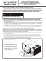
Fig ure 1
CONTROL ACCESS
EXHAUST HOOD
EXHAUST MOTOR & FAN
Figure 2
FORM # 610A-0709 (610A-0808)
I - Ship ping and Pack ing List
Package 1 of 1 contains:
1 - Power Exhaust Assembly
1 - Barometric Relief Hood
6 - #10 x ½ x 16 Hex Tec
1 - End Switch
1 - 1 ½" Wire Grommet
Check contents for shipping damage. Contact the last
carrier immediately if any shipping damage is found.
II - Ap pli ca tion
Power exhaust can be used in down flow and horizontal
economizer applications. This power exhaust is designed
to relieve excess pressure that may occur with
economizers or certain building conditions. All fan motors
are recognized by UL. Permanently lubricated ball bearing
and motor overload protection are standard.
FILTER ACCESS
Read these instructions in their entirety before proceeding with the installation of the power exhaust unit, control
components, and its wiring.
6, 7.5 and 10 Ton Pack age Sys tems - R4GM, R4GN, R6GP, P4SM, P4SN, P6SP,Q5SN, and Q6SP Se ries
Unit Model
Nortek Global HVAC
Part No.
Volts Phase
No. of
Fans
HP
High Speed
FLA Fuse MCA
2
MOP
2
CFM
1
RPM
R6GP and P6SP- 072* Se ries
R4GM, R4GN,and R6GP - 090* Se ries
P4SM, P4SN,and P6SP - 090* Se ries
547867
208
3 1 0.5 2350 1725
2.50 6A 3.13 5.63
230
3.00 6A 3.75 6.75
547868 460
3 1 0.5 2350 1725 1.50 3A 1.88 3.38
547890 575
3 1 0.5 2385 1750 0.88 2A 1.10 1.98
R4GM, R4GN,and R6GP- 120* Se ries
P4SM, P4SN,and P6SP- 120* Se ries
Q5SN and Q6SP - 090*/120* Se ries
547876
208
3 1 0.75 4900 1140
4.00 9A 5.00 9.00
230
4.00 9A 5.00 9.00
547877 460
3 1 0.75 4900 1140 2.00 4A 2.50 4.50
547891 575
3 1 0.75 4900 1140 1.50 3A 1.88 3.38
Note:
1. CFM is per fan curve @ 0.1" w.c. ex ter nal static pres sure
2. Applicable to R6GP, P6SP, Q5SN, and Q6SP Models only.
This kit is to be installed by a qualified service
technician in accordance with these instructions and
all codes having jurisdiction. Failure to follow these
instructions could result in serious injury, property
damage, or death. These instructions are primarily
intended to assist qualified individuals experienced in
the proper installation of this appliance. Some local
codes require licensed installation/service personnel
for this type of equipment.
Warn ing:
ECONOMIZER INSTALLED
ECONOMIZER BAROMETRIC RELIEF HOOD
III - In stal la tion and Elec tri cal Con nec tions
1. Disconnect all power to unit.
2. Cut and discard wire tie securing wire bundle to the damper motor
Table 1

INSTALLATION
INSTRUCTION
INSTALLATION INSTRUCTIONS FOR
POWER EXHAUST USED WITH Q5SN AND
R4G(M,N)-090/120 (R-22) UNITS AND P6SP, R6SP,
Q6SP-072/120 (R410A) UNITS
Important - DO NOT cut other wires. Inspect for damaged connections or loose wires.
3. Remove the barometric relief hood of economizer, if previously installed, and retain screws for later use. See Figure 2.
Notice to Installer: This accessory provides a switch for sensing economizer operation and will need to be
mounted and wired to the economizer prior to installation of the power exhaust unit. See installation instructions
provided with the switch for set up and connection to economizer for proper power exhaust operation.
Warn ing:
All electrical wiring must comply with the latest edition
of the National Electrical Code (NEC) - NFPA 70.
For R4G(M,N)- 090/ 120 (R-22) Models - IMPORTANT: See unit rating label before operating this accessory to
ensure correct field supply wire size has been installed to the unit for proper operation of this accessory.
4 Remove plastic hole plug (located on economizer panel between fresh air and return air vanes) and replace with 1 ½ "
bushing supplied with this kit.
5 Route power exhaust high voltage supply wiring with quick connect plug up through bushing and connect to unit power
exhaust plug located to the top right above unit filter rack assembly next to unit economizer plug. Ensure all wiring is
secured and away from the economizer vane travel.
6 Route power exhaust micro switch and low voltage control wiring up through bushing and follow installation
instructions provided with the switch. Ensure all wiring is secured and away from the economizer vane travel.
For Q5SN- 090/120 (R-22) Models and R6GP, P6SP, Q6SP – 072/090/120 (R410A) Models -
NOTE: Application of this accessory on Q5SN-090/120 or R6GP and (P6,Q6)SP–072/090/ 120 models requires a
separate branch circuit be brought to the accessory for proper operation. See Table 1 or the accessory rating
label for proper branch circuit electrical requirements. (Field Supplied)
4 Remove plastic hole plug (located on economizer panel between fresh air and return air vanes) and replace with 1 ½"
bushing supplied with this kit.
5 Route power exhaust micro switch and low voltage control wiring up through bushing and follow installation
instructions provided with the switch. Ensure all wiring is secured and away from the economizer vane travel.
6 Removal of the 6 pin/4 wire harness assembly from the "LINE" side of the power exhaust control fuse block is required
prior to field wire attachment. Attach properly sized field wire to control contactor.
DOWN FLOW APPLICATION
7. Secure power exhaust to the unit face
with screws provided.
8. Install barometric relief hood in front of
exhaust air opening.
9. Reconnect power to the unit. Energize
economizer to an opening greater
than what the power exhaust
activation switch is set for to verify
proper accessory operation.
FRESH AIR HOOD
EXHAUST AIR OPENING
BAROMETRIC RELIEF HOOD
Figure 3

HORIZONTAL APPLICATION
7. Secure power exhaust to side face of
the horizontal duct over the precut
hole with screws provided. Support
assembly as required. Caulk all
seams to ensure a leak free seal.
8. Install barometric relief hood in front of
exhaust air opening.
9. Reconnect power to the unit. Energize
economizer to an opening greater
than what the power exhaust
activation switch is set for to verify
proper accessory operation.
BAROMETRIC RELIEF HOOD
EXHAUST AIR OPENING
RETURN DUCT
SUPPLY DUCT
NEIPE07
SUPERSEDES 09-02-08
JULY 14, 2009
CUT OPENING
INSTALLATION
INSTRUCTION
INSTALLATION INSTRUCTIONS FOR
POWER EXHAUST USED WITH Q5SN AND
R4G(M,N)-090/120 (R-22) UNITS AND P6SP, R6SP,
Q6SP-072/120 (R410A) UNITS
Return Duct Size:
6 and 7.5 Ton Models - 31 ½" W x 12
3
8
" H
10 Ton Models - 31 ½" W x 19" H
Horizontal duct at unit requires 1" top and
bottom flanges and 2 ½" side flanges for proper
mounting and sealing to economizer and unit.
Power Exhaust Air Opening:
6 and 7.5 Ton Models - 30" W x 11 ½" H
10 Ton Model - 30" W x 18" H
Figure 4

Notes:
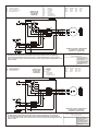
1 For R4G(M,N)- 090/ 120 (R-22) Models - Connect high voltage 6 pin/4 wire wiring harness to unit supplied plug.
For Q5SN- 090/120 (R-22) Models and R6GP, P6SP, and Q6SP – 072/090/120 (R410A) Models – Remove 6 pin/4 wire
harness assembly from the "LINE" side of control fuse block and connect properly sized (Field Supplied) branch circuit
wiring. See Table 1.
Date: July 1, 2009
Supercedes: 04-09-99
Drawn by: MGL
Unit #: 547867 / 547876
Di a gram#: 4650713W
Ap proved by:
COMPONENT CODE
C1 Contactor
ES1 End Switch
FB Fuse Block
FM Fan Motor
GRD Ground
P1 Fan Plug Male
P2 Unit Plug Male
S1 Control Box Female
WIRE COLOR CODE
BK/RD Black/Red BLK Black
YEL Yellow WHT White
ORG Orange RED Red
GRN Green BLU Blue
E# = WIRE END DESIGNATION
E2 STUD #6 18 Ga. Wire
E3 Female ¼ Quick Disc.
E4 Male ¼ Quick Disc. Insul
E6 Wire Nut Size 73B
HAR NESS LEADS
ARE 14 GA. WIRE
WITH NO END
DES IG NA TION
CON NEC TOR & CON TACT CON FIGU RA TION
P1 (303906) PLUG - (303912) PIN
S1 (303907) CAP - (303913) SOCKET
COMPONENT CODE
C1 Contactor
ES1 End Switch
FB Fuse Block
FM Fan Motor
GRD Ground
P1 Fan Plug Male
P2 Unit Plug Male
S1 Control Box Female
WIRE COLOR CODE
BK/RD Black/Red BLK Black
YEL Yellow WHT White
ORG Orange RED Red
GRN Green BLU Blue
HAR NESS LEADS
ARE 14 GA. WIRE
WITH NO END
DES IG NA TION
E# = WIRE END DESIGNATION
E2 STUD #6 18 Ga. Wire
E3 Female ¼ Quick Disc.
E4 Male ¼ Quick Disc. Insul
E6 Wire Nut Size 73B
Notes:
1 For R4G(M,N)- 090/ 120 (R-22) Models - Connect high voltage 6 pin/4 wire wiring harness to unit supplied plug.
For Q5SN- 090/120 (R-22) Models and R6GP, P6SP, and Q6SP – 072/090/120 (R410A) Models – Remove 6 pin/4 wire
harness assembly from the "LINE" side of control fuse block and connect properly sized (Field Supplied) branch circuit
wiring. See Table 1.
230 Volt 3 Phase Power Ex haust for
Q5SN and R4G(M,N)-090/120 and R6GP, P6SP, and
Q6SP-072/090/120 Units
CON NEC TOR & CON TACT CON FIGU RA TION
P1 (303906) PLUG - (303912) PIN
S1 (303907) CAP - (303913) SOCKET
208 Volt 3 Phase Power Ex haust for
Q5SN and R4G(M,N)-090/120 and R6GP, P6SP, and
Q6SP-072/090/120 Units
Date: July 1, 2009
Supercedes: 04-09-99
Drawn by: MGL
Unit #: 547867 / 547876
Di a gram#: 4650723W
Ap proved by:

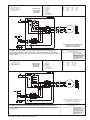
Notes:
1 For R4G(M,N)- 090/ 120 (R-22) Models - Connect high voltage 6 pin/4 wire wiring harness to unit supplied plug.
For Q5SN- 090/120 (R-22) Models and R6GP, P6SP, and Q6SP – 072/090/120 (R410A) Models – Remove 6 pin/4 wire
harness assembly from the "LINE" side of control fuse block and connect properly sized (Field Supplied) branch circuit
wiring. See Table 1.
COMPONENT CODE
C1 Contactor
ES1 End Switch
FB Fuse Block
FM Fan Motor
GRD Ground
P1 Fan Plug Male
P2 Unit Plug Male
S1 Control Box Female
WIRE COLOR CODE
BK/RD Black/Red BLK Black
YEL Yellow WHT White
ORG Orange RED Red
GRN Green BLU Blue
HAR NESS LEADS
ARE 14 GA. WIRE
WITH NO END
DES IG NA TION
E# = WIRE END DESIGNATION
E2 STUD #6 18 Ga. Wire
E3 Female ¼ Quick Disc.
E4 Male ¼ Quick Disc. Insul
E6 Wire Nut Size 73B
460 Volt 3 Phase Power Ex haust for
Q5SN and R4G(M,N)-090/120 and R6GP, P6SP, and
Q6SP-072/090/120 Units
CON NEC TOR & CON TACT CON FIGU RA TION
P1 (303906) PLUG - (303912) PIN
S1 (303907) CAP - (303913) SOCKET
COMPONENT CODE
C1 Contactor
ES1 End Switch
FB Fuse Block
FM Fan Motor
GRD Ground
P1 Fan Plug Male
P2 Unit Plug Male
S1 Control Box Female
WIRE COLOR CODE
BK/RD Black/Red BLK Black
YEL Yellow WHT White
ORG Orange RED Red
GRN Green BLU Blue
HAR NESS LEADS
ARE 14 GA. WIRE
WITH NO END
DES IG NA TION
E# = WIRE END DESIGNATION
E2 STUD #6 18 Ga. Wire
E3 Female ¼ Quick Disc.
E4 Male ¼ Quick Disc. Insul
E6 Wire Nut Size 73B
Notes:
1 For R4G(M,N)- 090/ 120 (R-22) Models - Connect high voltage 6 pin/4 wire wiring harness to unit supplied plug.
For Q5SN- 090/120 (R-22) Models and R6GP, P6SP, and Q6SP – 072/090/120 (R410A) Models – Remove 6 pin/4 wire
harness assembly from the "LINE" side of control fuse block and connect properly sized (Field Supplied) branch circuit
wiring. See Table 1.
575 Volt 3 Phase Power Ex haust for
Q5SN and R4G(M,N)-090/120 and R6GP, P6SP, and
Q6SP-072/090/120 Units
CON NEC TOR & CON TACT CON FIGU RA TION
P1 (303906) PLUG - (303912) PIN
S1 (303907) CAP - (303913) SOCKET
Date: July 1, 2009
Supercedes: 04-09-99
Drawn by: MGL
Unit #: 547868 / 547877
Di a gram#: 4650733W
Ap proved by:
Date: July 1, 2009
Supercedes: 04-09-99
Drawn by: MGL
Unit #: 547890 / 547891
Di a gram#: 4650743W
Ap proved by:
© Nortek Global HVAC
, LLC 2015. All Rights Reserved.
-
 1
1
-
 2
2
-
 3
3
-
 4
4
-
 5
5


Unbranded Q6SP Installation guide
- Type
- Installation guide
- This manual is also suitable for
Ask a question and I''ll find the answer in the document
Finding information in a document is now easier with AI
Related papers
-
Reznor R6GP Installation guide
-
Unbranded High Static Blower Drive Kit Installation guide
-
-
-
-
-
-
-
Broan R8GE Installation guide
-
Other documents
-
Essence CareHome ES700MGLS User manual
-
-
-
-
-
-
Lennox Power Exhaust Fan -- ZG/ZC/ZH 092-150 B Box Downflow - Raider - Micrometal Installation guide
-
General Monitors 610A Four Channel Combustible Gas Monitor Owner's manual
-
-
Assa Abloy MGL-01500ALS Series Installation guide