Page is loading ...

ALTEC
R
Temperature Differential Controller
DC220
Operating Instructions

ALTEC
CONTROLLER DC220
WWW.ALTEC.CC
Table of Contents
1 Introduction ................................................................................. 1
2 Features ....................................................................................... 1
3 Type designation................................. ........................................
4 Mounting .................. ................................................................ 2
5 Electrical connection .................................................................. 3
6 Front panel layout ....................................................................... 4
7 Operation ..................................................................................... 4
8 Controller configuration ......... ......................... 7
9 PID Auto-tuning ................................. ................................. 11
10 Sensor failure .. ........................................ 11
11 Linear input ............. ............................................... 12
Technical data .. ................. 15
Measurement range ... ..................................... .................. 15
. 1
....
...........................
.......
.................................
..................
............................................................
........... .

ALTEC
CONTROLLER DC220
None
RS232(3-wire), optical isolated, distance: 12m
RS485 .2km(2-wire), optical isolated, distance: 1
None
0
232
485
0
R
D
Relay, (NO, 3A/250VAC)
Analog: 0~10mA, 4~20mA, 0~20mA, 0~5V, 1~5V, 0~10V
0
None
L
Logic, 20V/10mA, drive SSR
T
Triac, drive SCR
R Relay, (NO, 3A/250VAC)
0 None
DC220
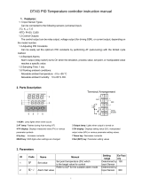
1 Introduction
2 Features
3 Type designation
Output 1
Output 2
Alarm 1
COMMS
Options
● 16-bits high speed A/D converter, high ● RS485/RS232 serial communications.
measurement precision.
● Wild range switching power supply(85~264V).
● Advanced PID control algorithm provide high
● Friendly user interface, easy to use.
control precision.
● More cost efficient.
● Standard thermocouple, Pt100, Cu50, RTD,
linear signal inputs
● Various optional outputs for different
applications.
.
The DC220 temperature difference controller has dual temperature signal inputs. The controller is idea for temperature
differential, pressure differential, solution ratio applications. Especially for central air conditioner control application.
1
WWW.ALTEC.CC

100
11.5
30
92
92
25
+0.5
-0.0
+0.5
-0.0
ALTEC
CONTROLLER DC220
OP1 OP2 RAMP AL1
PV
SV
COM MAN
ALTEC
DC220
PAR
A/M
96
96
8.8.8.8.
8.8.8.8.
PV
SV
4 Mounting
4.1 Dimensions
4.2 Fitting
Front view
Panel cut-out
Side view
Mounting screw
horizontal
vertical
25 mm
30 mm
For close mounting
Minimum spacing of panel cut-outs
● Prepare a rectangular cut-out in the panel to the size
shown above.
● Insert the controller from the front into the panel cut-out.
● From behind the panel, slide the mounting brackets into
the guides on the top and bottom sides of the housing. The
flat faces of the mounting brackets must lie against the
housing.
● Push the mounting brackets up to the back of the panel,
and tighten them evenly with a screwdriver.
2
WWW.ALTEC.CC

1
2
3
4
5
6
7
8
17
18
19
20
21
22
23
24
9
10
11
12
13
14
15
16
1
2
3
4
5
6
7
8
9
10
11
12
13
14
15
16
17
18
1919
2020
21
22
23
24
+
-
+
-
RTD
RTD
14
11
15
12
16
13
OUT2
OUT1
Input 1
Input 2
5
6
-
+
7
8
-
+
RS485
T/R( -)
T/R( +)
RS232
GND
TXD
RXD
ALTEC
CONTROLLER DC220
5 Electrical connection
5.3 Connection diagram
5.2 Rear terminals view
5.1 Notes on wiring
Power supply
100~260VAC
Thermocouple RTDRelayLogic/Analog
output
Alarm output
AL1
3
WWW.ALTEC.CC
For thermocouples inputs, please connect appropriate compensating cable.
For RTD input, the length and gauge of all three wires must be equal.
Input wire shall be separated from the power line and load line to avoid electrical noise.
The inputs to the controller must be between -10mV to 50mV, voltage signal which exceed
this range must be attenuated with an appropriately sized input adapter. Current signals are
converted to the -10 to 50mV range with a shunt input adapter.

ALTEC
CONTROLLER DC220
OP1 OP2 RAMP AL1
PV
SV
COM MAN
ALTEC
DC220
PAR
A/M
8.8.8.8.
8.8.8.8.
PV
SV
1
2
3
4
6 Front panel layout
PV Display
Indicates the Process Value
and parameters
Indicates the setpoint,
manual manipulation output,
parameter values, alarms code
Output 1 indicator(green)
Output 2 indicator(green)
SN Item Description
SV Display
Communication indicator(red)
OP1
OP2
COM
1
3
2
Manual operating mode
indicator(red)
MAN
Parameter setting key
Automatic/Manual key
Raise key
PAR
A/M
▲
4
Lower key
▼
Alarm 1 indicator(red)
AL1
7 Operation
7.1 Display & Basic Operation
There are two LED displays indicate the operating parameters.
The upper display(green) indicates the channel-1(input 1) measured temperature(T1) and temperature difference(dt).
On selecting a parameter, the appropriate parameter abbreviation appears.
The lower display(red) indicates the channel-2(input 2) measured temperature(T2) and the setpoint(SV). On selecting a
parameter, the appropriate parameter value appears here.
When the controller is powered on, the upper display indicates the basic models of the controller, and the lower display
indicates the software version.
The type of contents displayed in the upper and lower display depend on the parameters
3 seconds later, the upper display will indicate measured values (PV), and the lower display will indicate set values (SV),
or,
When the controller runs in manual control mode(indicator 'MAN' is ON), the lower display will indicate the output power.
Both the LED indicators ‘OP1’ and ‘OP2’ indicate the state of the relevant output. The LED is illuminated when the output
is 'ON'.
The LED indicator ‘COM’ flashes when the controller is in active communication with a host computer.
The LED indicator ‘RAMP’ is illuminated when the setpoint is ramping towards the target setpoint (only if ramp-to-setpint
has been configured).
The LED indicator ‘MAN’ indicates manual operating mode, the indicator flashes if sensor break is detected.
D,S1 and D,S2.
D,S1 = T 1, upper display indicates T1
D,S1 = DT, upper display indicates dt
D,S1 = R1, upper display indicates T2/T1
D,S2 = T2, lower display indicates T2
D,S2 = SP, lower display indicates SV
D,S2 = (1, lower display indicates C1
4
WWW.ALTEC.CC

ALTEC
CONTROLLER DC220
7.2 Setpoint adjusting
7.3 Automatic/Manual mode
In automatic control mode, the upper display indicates channel-1 measured temperature(T1) or temperature difference
between T1 and T2(dt = T1-T2), the lower display indicates channel-2 measured temperature(T2) or setting value or
setting ratio.
Press keys ▲ or ▼ to increase or decrease setpoint, keeping it pressed results in a progressively faster variation.
Adjustable range: SP L ~ SP K.
With the Auto/Manual key('A/M'), the controller can be switched between automatic mode and manual mode.
When in manual mode, the indicator ‘MAN’ will be lit. The output power will appear on the lower display, the value can be
modified by pressing and key. Adjustable range: L PL K
PL .
The automatic/manual exchange function can be disabled by
If set the parameter ‘Automatic/Manual enable’(code: A K) to AVTO, the automatic/manual exchange function will be
disabled.
If set the parameter A K to KAND, the automatic/manual exchange function will be enabled.
When the controller runs in the automatic control mode and the automatic/manual exchange function has been disabled,
press A/M key, the output power will appear in the lower display.
▲ ▼ utput power low limit ) ~ utput power high limit
)
o (code: o (code:
5
WWW.ALTEC.CC

ALTEC
CONTROLLER DC220
Operation parameter list
Mnemonic
T2
TVNE
AL 1
KYS1
PROP
INT.T
K C.T
LOC
DT
SN
4
5
6
7
8
11
12
14
15
Parameter
Temperature 2
Difference of Temperature
PID Auto-tune
Alarm value 1
Alarm 1 hysteresis
Proportional band
Integral time
Output cycle
Configuration password
Adjustable Range
0FF
ON
Measurement range
0.01~99.99
1~9999 °C
0FF, 1~8000 sec.
0.1~240.0 seconds
0~9999
Comments
Input 2 measured temperature(Read only)
DT = T1 - T2 (Read only)
T 1
3 Temperature 1 Input 1 measured temperature(Read only)
[ 1
1 Ratio Coefficient 0.01~99.99
SP
2 Setpoint
SP K ~ SP L
AL2
KYS2
9
10
Alarm value 2
Alarm 2 hysteresis
Measurement range
0.01~99.99
DER.T
13 Derivative time
0FF, 1~999 seconds
Turn off PID auto-tune
Turn on PID auto-tune
7.4 Modifying the Operation Parameter
When the controller is in the PV/SV displaying status, press PAR key and hold for 3 seconds reveals the first
parameter. The parameter value can either be modified with the or key, or left unmodified. Press PAR
key again, the next parameter and its current value appears, the modified data has been saved.
or there’s no key operation within 16 seconds, the menu times out
automatically.
▲ ▼
If the last parameter is displayed
1). Regulation parameters - PROP,INT.T,DER.T
These three parameters directly affect the precision of control. The PID auto-tuning function could automatically
measure, compute, and set these three constants. If the controller is configured as an ON/OFF controller([TRL = 0N.0F),
the proportional band(PROP) becomes the output hysteresis.
proportional band(PROP) is the band of error within which the power output is proportional to the error. Error values
outside this band give 100% or 0% power output. If the proportional band is too narrow it will give control resembling
on/off control with continuous oscillation. Wide proportional bands give stable but sluggish control with an offset in the
steady-state condition.
Parameter INT.T provides automatic compensation for long term control offsets. It is the time taken for the output to
change by one proportional band width for a constant error equal to the proportional band. Typically this must be set to a
value longer than the response time of the process being controlled.
The parameter DER.T provides anticipation and fast recovery from disturbances. It can be taken as the 'look ahead' period
of the controller. It is typically set to a time approximately one sixth of the integral time.
2). Output cycle time - K C.T
If output 1 was set as time-proportioned output(0P1 = TP), the output cycle time(code: K C.T) should be set to high
values(e.g. 10 seconds) if contactors are used, and to low values(e.g. 2 second) if thyristors or SSR are used.
Operation parameters description
Disappears when (TRL = 0N.0F
Disappears when KYS = 0FF
Disappears when KYS = 0FF
Appears when FVNC = PRO
6
WWW.ALTEC.CC

ALTEC
CONTROLLER DC220
SN
Configuration parameter list
1
2
3
5
7
8
Mnemonic
SP K
SP L
K PL
0FS1
( F
SN
Parameter
Setpoint low limit
Adjustable range
Measurement range
Comments
Output power high limit
Input 1/calibration offset
°C/°F unit selection
( Centigrade
F Fahrenheit
0.0~100.0
0.00~10.00
Input signal
always > SP L
always < SP K
Disappears when SN = linear signal inputs
J thermocouple
K thermocouple
E thermocouple
R thermocouple
S thermocouple
B thermocouple
T thermocouple
Pt100
Pt100(0.1 prec)
Cu50
Cu50(0.1 prec)
Linear input
Linear input (0.1 prec)
Pressure resistance signal
Pressure resistance signal (0.1 prec)
12
(TRL
Control algorithm
0N.0F
P ,D
ON/OFF control
Proportional integral derivative(PID) control
9
10
ADDR
BAVD
Instrument address
Baud rate
00 99~
600, 1200, 2400
4800, 9600, 19.2
13
0P1
Output 1
(main output)
TP
0-20
4-20
Time-proportioned output
0~20mA output
4~20mA output
Setpoint high limit
Measurement range
4
L PL
Output power low limit
0.0~100.0
6
0FS2
Input 2/calibration offset
-9.99~99.99
8 Controller configuration
In order to get the best control performance, DC220 must be set properly.
1) Press PAR key and hold for 3 seconds to enter the 1st level menu(i.e. operation parameter list);
2) Press PAR key to scroll the parameter to LOC and set its value to
3) Press PAR key and key and hold for about 3 seconds, the first parameter appears on the upper display,
at the same time the parameter value appears on the lower display. The values can be modified by pressing
keys ▲ and ▼. After modification, press the PAR key, the next parameter appears, the modified data has
been saved in the memory.
If the last parameter is displayed or there is no key operation within 16 seconds, the controller will time out
automatically.
After configuration, set the configuration password(code LOC) to data other than 808 in order to protect the
parameter values from being inadvertent modification.
808(the initial password);
▲
JTC
[ATC
ETC
RTC
STC
BTC
TTC
RTD
.RTD
CV
.CV
L,N
.L,N
PRE
.PRE
11
FVNC
Controller Function
DT
PRO
Temperature differential controller
Ratio controller(optional)
7
WWW.ALTEC.CC

22
23
24
25
26
Control action
Measurement range
upper limit(sensor break)
Input filter
Process scaling
(straight line equation)
ACT
K ,L
LO L
F ,L
PROC
REV
D ,R
P 1
P2
[ 1
[2
0.01~99.99
-999~9999
Reverse control
Direct control
Appers only when input are linear input(SN is set
as L,N or .L,N, PRE or .PRE)
20
A K
Auto/Manual enable
Changeover locked out
Changerover possible
AVTO
KAND
Measurement range
lower limit(sensor break)
-999~9999
16
17
ALO1
ALO2
Alarm 1
Alarm 2
Appears only if 0P2
is configured as AL02
K ,AL
LOAL
KDA
LDA
DAO
NDAO
POVT
Full-scale high alarm
Full-scale low alarm
High-deviation alarm
low-deviation alarm
outside deviation band alarm
Inside deviation band alarm
Alarm when program halt
ALTEC
CONTROLLER DC220
14
15
1AL
2AL
Object of Alarm 1
Object of Alarm 2
T 1
T2
DT
Temperature 1
Temperature 2
Difference of Temperature
18
D,S1
Contents of upper
display indicates
T 1
DT
R1
Display temperature 1
Display difference of temperature
Display R1=T2/T1
19
D,S2
Contents of lower
display indicates
T2
SP
[1
Display temperature 2
Display setpoint
Display ratio setpoint C1
21 Alarms hysteresis
KYS
0FF
ON
Turn alarms hysteresis off
Turn alarms hysteresis on
Configuration parameter list(continued)
Configuration parameter description
1). Controller Function - FVNC
When FVNC = DT, the controller performs as temperature differential controller, difference of temperature is
dt(dt = t1 - t2).
When FVNC = PRO, the controller performs as ratio controller, the temperature 2(measured by input 2) times
the ratio coefficient will be the setpoint of temperature 1.(In formula: SP1 = t2 * C1)
2). Input Signal - SN
The parameter SN should be set to the correct sensor type the controller connected, otherwise the measured value will be
incorrect.
E.g. for Pt100 RTD input, set SN to RTD or .RTD. And for 4~20mA linear signal input, set SN to L,N or .L,N.
8
WWW.ALTEC.CC

ALTEC
CONTROLLER DC220
PV
Output
100%
0%
ON/OFF Control
SP
PROP
PV
Output
100%
0%
PID Control
SP
3). Control Algorithm - [TRL
There are 2 types of control algorithm can be selected for the controller: ON/OFF and PID.
If (TRL=0N.0F, the controller is configured as an ON/OFF controller, the output hysteresis is set using the proportional
band(PROP). The ON/OFF control is intended for applications which needs no high control precision. In PID control mode,
the output can be set to mV, mA or time-proportioned.
If (TRL=P,D, the controller is configured as a PID controller, PID is intended for high precision control applications. See
the figure below.
4). Display Contents Configuration - D,S1 & D,S2
The upper and lower displays’ displayed contents can be configured very flexibly. For detailed settings, see the
parameter list.
5). Output Parameter - 0P 1 & K C.T
The setting value for 0P1 depends on which type of output drive device the controller installed.(check the controller’s part
number) There are generally two types of outputs.
Time proportioned output
This applies to relay, logic or triac outputs(i.e. ON/OFF devices) and PID control. The percentage 'ON' time of the device
over a period is proportional to the power demand of the PID. Appropriate cycle times can be selected to suit the type of
output device and the process response time.
Analogue output
Where continuously variable control is required. DC volts or current are available. 4 to 20 mA is a standard output.
If the output module is relay, logic or SCR, 0P1 would be set to TP output.
If the output module is analog output, OP1 would be set to 0~20 mA or 4~20 mA.
Especially, if output 1 was set to time-proportioned output(0P1 = TP), the output cycle time(code: K C.T) should be set to
high values(e.g. 10 seconds) if contactors are used, and to low values(e.g. 2 second) if thyristors or SSR are used.
6). Control Action - ACT
A reverse acting controller(ACT = REV) will reduce its output as the process variable increases. REV should be selected for
temperature control loops with the heat output.
A direct acting controller(ACT = D,R) will increase its output as its process variable increases. D,R should be selected for
temperature control loops with the cool output.
●
●
9
WWW.ALTEC.CC

ALTEC
CONTROLLER DC220
Alarm LED
ONOFF OFF ON OFF
High-Deviation Alarm(KDA)
Full-scale High Alarm(K ,AL)
Full-scale Low Alarm(LOAL)
Outside Deviation Band Alarm(DAO) Inside Deviation Band Alarm(NDAO)
△
AL1, AL2
△
AL1, AL2
△
Alarm value
△
Alarm value
△
Alarm value
△
Alarm value
△
Alarm value
Alarm LED
ONOFF OFF
PV
Time
Hysteresis
Alarm LED
ONOFF
OFF
PV
Process value
Hysteresis
Alarm LED
▲
SV
▲
SV
▲
SV
ON OFF OFFON ON
Alarm LED
ONOFF OFF
PV
Process value
Time
Hysteresis
Deviation AL1, AL2
Derivation AL1, AL2
Derivation AL1, AL2
Deviation AL1, AL2
Deviation AL1, AL2
Deviation AL1, AL2
Low-Deviation Alarm(LDA)
▲
SV
Alarm LED
ONOFF
OFF
PV
Time
Hysteresis
Time Time
Hysteresis
Hysteresis
Hysteresis
Hysteresis
PV
Process value
PV
△
Alarm value
Time
Process value
Process value
Process value
7). Alarms - ALO 1, ALO2, 1AL, 2AL
.
1). Full-scale High Alarm(K ,AL) Alarm operates above an absolute level.
2). Full-scale Low Alarm(LOAL) Alarm operates below an absolute level.
3). High-Deviation Alarm(KDA) Alarm operates above a defined band above the control level.
4). Low-Deviation Alarm(LDA) Alarm operates below a defined band below the control level.
5). Outside deviation band alarm(DAO) Alarm operates outside a defined band around the control level.
6). Inside deviation band alarm(NDAO) Alarm operates inside a defined band around the control level.
ysteresis
ysteresis . See the figures below.
Six different types of alarm can be configured with ALO1 and ALO2
H is used to provide a definite indication of the alarm condition and to prevent alarm relay chatter. The
h is KYS1 and KYS2
10
WWW.ALTEC.CC

ALTEC
CONTROLLER DC220
PV
setpoint
CP
PV2
PV1
Output
100%
0%
Self-tuning from setpoint-heating process
9 PID Auto-tuning
10 Sensor failure
A sensor break and likewise an input error occurs when the input is open circuit or the measured value at the input over
or under ranges the linerisation span of the controller.
If the input is open circuit or the measured value is over range, error code SNB appears on the upper display. In an under
range condition or the sensor is shorted, error code VR appears on the upper display. In both case, the output will be
closed, the output becomes 0, at this time the output can be modified by pressing the and key, the indicator ‘MAN’
will flash.
Once failure eliminated, the controller will return to automatic control mode.
▲ ▼
In order to achieve a good control performance, the PID control
parameters(PROP INT.T DER T) must be optimized first. The PID
auto-tuning function could automatically measure, compute,
and set PID constants.
Auto-tuning can be activated under the following conditions:
●Automatic operating(closed loop)
●PID control algorithm
Before activating the auto-tuning, set SV(Setting Value) to the
desired value. By setting the parameter TVNE to ON, the auto-
tunging will start. During auto-tuning execution, the code TVNE
and the setpoint will flash in the lower display alternately.
The tuning operation is finished when the code TVNE no longer
flashes. The user can abort self-tuning at any time by setting
the parameter TVNE to 0FF.
, , .
11
WWW.ALTEC.CC
During auto-tuning, the controller will execute ON/OFF regulation, PV will oscillate, 1.5 period later, auto-tuning finished.
According to the period and amplitude of the oscillation, the controller will calculate the optimum PID parameters and
stored them in the memory automatically.
During auto-tuning, do not change any of the parameters, because each modification of setpoint will restart the auto-
tuning.
If the user use PI(Proportional Integral) control algorithm, please set the derivative time(code: DER.T) to 0FF before turning
on the PID auto-tuning, the derivative time will not be change during the auto-tuning process. PI control is suited to
systems which allow of no frequent outputs variation.

-10 10 20 30 40 50
Input signal (mV)
LOL
VR( )Sensor break/short pause
P1(X1, Y1)
P2(X2, Y2)
-999 (L,N )
9999( )L,N
-99.9(. )L,N
999.9(. )L,N
SN B( )Sensor Break
K ,L
Display unit
ALTEC
CONTROLLER DC220
Set the “input signal” parameter SN to L,N or .L,N.
Set proper “input filter”(code: F,L) value. The greater the F,L, the more stable display but slower response.
11 Linear input
12
WWW.ALTEC.CC
Principle
If for the given input signal X1, the
corresponding display value is Y1; And for the
given input signal X2, the corresponding display
value is Y2. Then for linear input signals, the
two points define a straight line which maps the
input signal to the display unit.
The figure right illustrates the principle clearly.
11.2 Parameter settings
11.3 Calibration procedure
11.1 Introduction
To measure physical quantities such as humidity and pressure or measure temperature by using transmitters, the
physical quantities must be converted to analog signals, and set the “input signal” parameter(code: SN) to L,N or .L,N.
The input to the controller must be between -10mV to 50mV, Voltage signal which exceed this range must be
attenuated with an appropriately sized input adapter. Current signals are converted to the -10 to 50mV
range with a shunt input adapter.
e.g. Input Adapter
4 to 20 mA Ri=2.5Ω
0 to 10 V Ri=1k/200kΩ
The following practical examples illustrate calibration procedures clearly.
Assume that there are two temperature transmitters: Transmitter 1 is connected to input 1 while transmitter 2
is connected to input 2.
Transmitter 1 outputs a 4~20 mA signal which corresponds to display unit 0~50°C, transmitter 2 outputs a
which corresponds to display unit 0~1004~20 mA signal °C.
Note that the transmitters can also be replaced by standard signal generators, in the examples, we use
signal generator to get the mA signals.
Note:
* Both the two inputs must be connected at the same time. When calibrate e.g. input 1, make sure input 2 is
0, and vice versa.
* Input 1 and input 2 can’t be supplied with the same power supply.

ALTEC
CONTROLLER DC220
PROC
----
PROC
P2
P2
60.0
P2
50.0
50.0
NO
50.0
YES
P2
P2
Display
PROC
----
Step
9
2
3
4
5
6
Button Operation
Press PAR key until PROC appears in the upper display
Press key, P2 appears in lower display▲
Press PAR key, the number in the lower display will be the value after adjustment
assigned to injected input signal
Press ▲ and ▼ key to adjust the number in the lower display until it corresponds
to the value represented by the injected signal(here 50)
Press PAR key
Press ▲ key to affirm
7
Press PAR key, P2 appears in the upper and lower display at the same time
8
5 seconds later, the scaling of the 2nd point is completed
PROC
----
PROC
P1
P1
15.0
P1
0.0
0.0
NO
0.0
YES
P1
P1
Display
PROC
----
Step
1
2
3
4
5
6
Button Operation
Press PAR key until PROC appears in the upper display
Press ▲ key, P1 appears in the lower display
Press PAR key, the number in the lower display will be the value after adjustment
assigned to the injected input signal
Press ▲ and ▼ key to adjust the number in the lower display until it corresponds
to the represented by the injected signal
Press PAR key
Press ▲ key to affirm
7
Press PAR key, P1 appears in the upper and lower display at the same time
8
5 seconds later, the scaling of the 1st point is completed
11.3.1 Input 1 Calibration
2). P Calibration2
1
Apply a signal equals to 20mA for the second setup point(P2)
9
Connect source.(form signal generator or sensor to input 1 terminals)
Apply a signal equal to 4mA.
13
WWW.ALTEC.CC
1). P1 Calibration

ALTEC
CONTROLLER DC220
PROC
----
PROC
[2
[2
80.0
[2
100.0
100.0
NO
100.0
YES
[2
[2
Display
PROC
----
Step
9
2
3
4
5
6
Button Operation
Press PAR key until PROC appears in the upper display
Press key, [2 appears in lower display▲
Press PAR key, the number in the lower display will be the value after adjustment
assigned to injected input signal
Press ▲ and ▼ key to adjust the number in the lower display until it corresponds
to the value represented by the injected signal(here 100)
Press PAR key
Press ▲ key to affirm
7
Press PAR key, [2 appears in the upper and lower display at the same time
8
5 seconds later, the scaling of point C2 is completed
PROC
----
PROC
[ 1
[ 1
5.0
[ 1
0.0
0.0
NO
0.0
YES
[ 1
[ 1
Display
PROC
----
Step
1
2
3
4
5
6
Button Operation
Press PAR key until PROC appears in the upper display
Press ▲ key, [ 1 appears in the lower display
Press PAR key, the number in the lower display will be the value after adjustment
assigned to the injected input signal
Press ▲ and ▼ key to adjust the number in the lower display until it corresponds
to the represented by the injected signal
Press PAR key
Press ▲ key to affirm
7
Press PAR key, [ 1 appears in the upper and lower display at the same time
8
5 seconds later, the scaling of point C1 is completed
1). C Calibration1
2). CalibrationC2
1
Apply a signal equals to 20mA for the second setup point(C2)
9
Connect source.(form signal generator or sensor to input 2 terminals)
Apply a signal equal to 4mA.
14
WWW.ALTEC.CC
11.3.2 Input 2 Calibration

ALTEC
CONTROLLER DC220
Technical data
Sample rate
Alarms
Control algorithm
Power supply
Environmental
Relay, (NO, max.250VAC/3A)
Modes: upper and lower limit alarm, and deviation alarm
125ms
ON/OFF
PID with PID Auto-tuning
85~264VAC, 45/60Hz
Temp: 0~50°C,Rel. Humidity:≤85%
Dimensions
W96 H96 D100mm× ×
Output
Relay, (NO, max.250VAC/3A)
Logic, 20V/10mA, Drive SSR
SCR
Analog:0~10mA, 4~20mA, 0~20mA or 0~5V, 1~5V, 0~10V
Input
Thermocouple: Type J, K, E, R, S, T, B
RTD: Pt100, Cu50
Analog: 0~20mA, 4~20mA, -10.0~50.0mV, 0~10V
Communication
RS232, RS422, RS485
Accuracy ±0.2%FS+1 digital
Code
J T C
CATC
ETC
RTC
STC
BTC
TTC
RTD
.RTD
Input
J thermocouple
K thermocouple
E thermocouple
R thermocouple
S thermocouple
B thermocouple
T thermocouple
Pt100
Pt100(1/10’s prec)
Measurement Range(°C)
-135~1000
-255~1395
-99~749
-50~1767
-50~1767
-50~1967
-260~400
-100~1000
-99.9~999.9
Measurement Range(°F)
-211~1832
-427~2543
-427~1380
-58~3213
-58~3213
-58~3313
-436~752
-100~1000
-99.9~999.9
Measurement range
CU
Cu50 -50~150 -50~150
.CU
Cu50(1/10’s prec) -49.9~149.9 -49.9~149.9
L,N
Linear -1999~9999 -1999~9999
.L,N
Linear(1/10’s prec) -199.9~999.9 -199.9~999.9
PRE
Pressure resistance signal
-1999~9999 -1999~9999
.PRE
Pressure resistance signal
(1/10’s prec)
-199.9~999.9 -199.9~999.9
15
WWW.ALTEC.CC
/