Acewell ACE-MD085-254 User manual
- Category
- Bicycle accessories
- Type
- User manual
This manual is also suitable for

ATV/Motorcycle/Scooter Computer
ACE-MD085-5XX-AB/CP User Manual
Thanks for purchasing the Motorcycle/Scooter/ATV computer; this manual is specifically
designed for ACE-MD085-5XX-XX series. The series includes different models, each
model has same functions but with different LED indicators. You may find that the photo
has a set of LED indicators different from your computer, the photo is for reference
only.
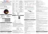
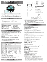
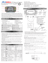
1. Tachometer Scale 7. Shift warning indicator
2. Bar-tachometer 8. RESET Button
3. Bar temperature gauge 9. MODE Button
4. 1st row: Speedometer 10. Gear Indicator
5. 2nd row: Other functions 11. Bar Fuel gauge
6. LED Indicators 12. 12/24HR clock
FEATURES
PANEL DESCRIPTIONS
Simultaneously displays tachometer, speedometer, gear indicator, clock, fuel
gauge, bar-graph temperature meter and one of the other functions.
Main unit with Aluminum forging CNC upper ring and built-in 5-7 LED
indicators for different applications.
Built-in gear indicator which calculates gear comparing speed and RPM, and
“gear indicator off” mode for Automatic vehicles.
Built-in RGB LED backlight, user can adjust his/her prefer backlight color.
On some models the backlight can be controlled separately from the ignition
power.
Bar-graph tachometer has scale of 12,000rpm, digital tachometer is up to
19,900rpm.
End user is able to adjust odometer when the odometer is less than 30km
/18.6 miles.
Acceleration and deceleration timers as well as distance timer for racing
practice.
Built-in air temperature sensor which installed outside the housings.
Fast processor so can connect to pulse type gearbox speed sensors.
Universal wheel circumference setting range: 1-3999mm.
Fuel gauge includes +/- 30 80Ω, 100Ω, 250Ω and 510Ω options for fuel
sender input resistance. In reserve mode, the fuel gauge is not displayed and
fuel symbol lights when the input wire is connected to -ve. The gauge can be
switched off entirely if not required.
Flexible battery warning voltage setting from 11.0 to 14.9V.
Speedometer can show nearest 0.1 mph or km/h speed if required by user.
E.g. 100 or 100.5
Includes bracket, RPM sensing wire, speed sensor, PT1/8 temperature sensor,
air temperature sensor, fitting kits and wiring harness.
Excellent water resistance, anti-vibration structure and noise immunity design.
RPM sensor mounting: RPM Input, Either one
1. Signal intensity from ignition coil is dependent on vehicle type.
2. Coil 2-5 turns around spark plug lead, with more turns creating steadily
stronger signal, fewer turns creating weaker signal.
3. The RPM circuit is designed for most bikes, however some bikes’ signal is too
strong if the RPM looks like much more than actual RPM and unstable,
please connect the included 1M Ohm resistor in series to solve it.
SPEED SENSOR Mounting:
ACEWELL has several speed sensors; the unit may include one of them. If
the model is intended to be connected to a gearbox electronic speed output to
obtain the speed reading, no speed sensor will be included.
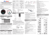
Reed Speed Sensor and Magnet:
1. This sensor is universal sensor for motorcycle, find a rotating part to install
magnet (for example disk, sprocket or driveshaft) and a location to install
the sensor where it can be aligned to the magnet.
2. Align the center of the magnet to either of the sensor marking lines or the
side of the sensor. The magnet must not travel down the body of the sensor
3. Installing the sensor parallel to the vibration direction creates optional
anti-vibration effect.
4. Make sure the gap between the magnet and the sensor is within 8mm.
Hall Effective Speed Sensor and Magnet:
1. This is universal sensor for ATV front or rear wheel installation or motorcycle
front wheel installation. For some fitments an accessory speed sensor holder
may need to be purchased.
2. Find a rotating part to install magnet (for example disk, sprocket or driveshaft)
and a location to install the sensor where it can be aligned to the magnet
3. Align the center of the magnet to center of side face of the sensor.
4. Make sure the gap between the magnet and the sensor is within 5m
Specific Hall sensors:
Cable drive adaptors for most bikes originally fitted with cable driven
speedometers or milemeters are available. When using these cables it is
necessary to divide the circumference setting by the number of rotations of the
cable per rotation of the wheel.
Thermo Sensor and Sensor Tube:
1. The unit includes a water temperature sensor; you have to purchase a suitable
water pipe temperature sensor tube to install the sensor easily.
2. Cut the water pipe, insert the temperature tube into the pipe and secure it by
attached pipe clamps.
3. Screw the sensor into the tube.
4. If your vehicle is fitted with a thermostat that stops water flowing to the radiator
when the engine is cold, you will not get a reading until the thermostat opens
Air Temperature sensor:
1. MD085-5XX series includes an air temperature for outdoor temperature
measurement.
2. Plug the sensor’s connector to the relative connector from main
SPECIFICATIONS
Functions SpecificationsSymbol
Speedometer
Maximum speed
Average speed
Max. RPM
Max RPM
Trip meter
Trip 1/2/3
Odometer
Odometer
12/24 Hour Clock
Riding timer R.Time
Km/h / MPH
MAX SPD
AVG SPD
100 19,900 rpm, 100rpm increment
2.4~300.0 km/h (187.5MPH)
2.4~300.0 km/h (187.5MPH)
2.4~300.0 km/h (187.5MPH)
0.00~999.99 KM/Miles
0 - 999999 KM, 0-624999 Miles
0:00’00” – 11H59’59” / 23H59’59”
0 – 9999H59’
0 – 99H59’59”
0 – 9999H59’
Gear indicator
1-5 bars, +/- 30 80Ω, 100Ω, 250Ω,
510Ω, off mode or RES mode.
8-18VDC, battery voltage warning settable
0 180 / 32 356 , off or Hi modes.
-20 60 / -4 140
0 180 / 32 356
1-5 bars or Off mode.
Bar-Fuel Gauge
N, R, 1, 2,...8 or off
Total Riding Time
Hour meter
HR Time
88:88(AM/PM)
Volt meter
VOLT
Engine Temperature
Air Temperature
MAX Temperature 1/2
Bar Temperature
DstTimer
AccTimer
DstTimer
Maintain
0 to 1/4 mile. 0 to100Meter, 0 to 400Meter
0 to 100km/h, 50 to 70mph
100km/h to 0km/h
0 9999H / 0 9999Km or Miles adjustable
Distance Timer
Acceleration Timer
Deceleration timer
Maintenance reminder
MAXTEMP1/2
TEMP1
TEMP2
T.Time
Power Input DC 8-18V
Speed Sensor Reed, 2 or 3 wires Hall-effect Sensor
Tachometer input CDI or Ignition Coil Signal or ECU
Wheel circumference setting 1mm-3999mm (1mm increment)
Temperature sensor PT1/8” thermistor sensor
Air Temperature sensor Air thermistor sensor
Dimensions Ø85*56.1mm
: Bar-Graphic Tachometer
The bar tachometer is 12,000rpm.
Km/H or MPH: Speedometer
1. Displays speed meter up to 300 Km/H or 187.5 MPH.
2. Speedometer can show nearest 0.1 mph or km/h speed if required by user. E.g.
99 or 99.9
3. The maximum frequency of software divider is 7K Hz.
4. The speed can be less than 399.9 KM/H in case the setup is using software
divider for speedometer, for example the maximum speed is 250KM/H in case
setup of software at 105P and the wheel circumference at 1277mm.
RPM: Digital Tachometer
1. It displays digital tachometer up to 19,990RPM and displays 19,999rpm when
tachometer is over 20,000rpm..
2. Tachometer signal can pick up from either CDI or Ignition Coil Signal.
Shift Warning RPM
1. The function enables you to set up a shift warning RPM.
2. Shift warning LED indicator flashes when RPM reaches setting value, and stops
flashing after you shift gear.
MAX RPM: Maximum Tachometer
Displays highest tachometer achieved since last Reset operation.
MAX SPD: Maximum Speed Meter
Displays highest speed achieved since last Reset operation.
AVG SPD: Average Speed Meter
It calculates average speed from last RESET. The AVG is calculated from TRIP 1
be divided by RT.
TRIP 1/2: Trip Meter 1 or 2
Trip 1 or Trip 2 function accumulates distance travelled since last RESET.
TRIP 3: Trip Meter 3
1. TRIP-3 function appears and starts to accumulate trip distance meanwhile
flashes the last fuel bar automatically at low fuel warning status.
2. The LCD screen will auto change to the Trip 3 screen after 4 seconds of button
operations at low fuel warning status.
3. TRIP-3 be reset to zero automatically when fuel is added to over the low fuel
warning level.
Odometer:
1. Odometer accumulates total distance traveled.
2. Odometer data is adjustable when it is less than 30km (18.6 Miles), after that it
stored in memory and cannot be reset.
R. Time: Riding Timer
1. Calculates total running time since last RESET.
2. Counter automatically begins with movement.
T. Time: Total Riding Timer
1. Calculates total riding time fr om the beginning of the bike.
2. TT data is stored in memory, and couldn’t be reset.
HR Time: Total Hour Meter
1. Calculates total engine operation time since installation.
2. Count automatically begins with engine starting.
3. HR Time data is stored in memory, and couldn’t be reset.
: 12/24 hour Clock
It displays 12 or 24 hour current time.
TEMP1: Digital Engine Temperature Meter
1. It displays -L- or -L- when temperature is lower than 40 or 104, and
displays -H- or –H- when temperature is over 180 or 356.
2. The LCD screen jumps to TEMP 1 screen automatically, flashes temperature
bar and -H- as well backlight color when the thermo sensor detects
temperature higher than the maximum preset temperature.
3. The LCD screen will auto change to the TEMP 1 screen and flashes
bar-temperature and -H- after 4 seconds of button operations at over
temperature status. Backlight always flashes at over temperature status.
4. Stop engine until temperature cooling down to protect your engine.
TEMP 2: Air Temperature
It displays air temperature from -20(-4 ) to+60(+140)
MAXTEMP1/2: Maximum Temperature 1/2*
Displays highest temperature achieved since last Reset operation.
Maintain: Maintenance Reminders
1. It counts down the preset Maintain entered time or distance since last RESET.
2. It accumulates Maintain when the count down reaches to “0”, and symbol of
“Maintain” flash to remind you to maintain oil or parts.
3. Push and hold RESET button to reset and restart the maintenance reminder
after maintained.
VOLT: Digital Voltage Gauge
It checks bike’s battery and charging systems health.
: Gear Indicator
1. The gear indicator has each one wire for N and R, connect wires to N and R
gears firstly.
2. The gear indicator calculates gear comparing speed and RPM then displays
gear position.
3. User has to training the gear indicator before use it.
:Bar Thermometer*
1. Have 5 bars to indicate engine temperature.
2. The 3rd bar counts from bottom be turned on and over temperature LED
flashes when thermometer reaches the preset warning temperature, each
+/-15 lights on/off a bar base on the 4th bar.
3. The bar-temperature flashes when the measured temperature is higher than
the preset warning temperature.
:Fuel Gauge
1. Has 5 bars to indicate how much fuel remains.
2. To use as a fuel gauge, it built-in F10 E250, F10 E510, F30 E80,
F100E10,F250E10, F510E10,F80 E30 OFF Ohm fuel sender resistance,
FXXX means full fuel resistance, EXXX means empty fuel resistance, the fuel
bars will disappear when you select “OFF” mode. Last bar flashes to indicate
low fuel level automatically. F30 E80 and F80 E30 are for vehicle application.
3. To use as a reserve indicator, connect the reserve switch to the input and put
into “RES” mode. When the switch pulls the input to –ve the backlight will flash
different color and the last fuel-bar flash. On vehicles with temperature based
sensors a 68 ohm 5w resistor needs to be connected between the input wire
and 12v (switched)
4.If the gauge is not required they can be switched off
DstTimer: Distance Test Timer
1. The DstTimer can be set 100meter or 400meter.
2. The unit calculates trip timer auto- start when receive speed signal and auto-
stop when the bike/vehicle reaches the preset distance.
AccTimer: Acceleration Timer Test
1. The AccTimer can be set 0-100Km/H acceleration test.
2. The unit calculates acceleration timer auto- start when receive speed signal
and auto- stop when the bike/vehicle reaches the preset speed.
DecTimer: Deceleration Timer Test
1. The DecTimer can be set 100 to 0Km/H deceleration test.
2. The unit calculates deceleration timer auto- start when speed decelerates to
100km/h and auto- stop after 2 seconds of the bike/vehicle stop then returns
the over counted 2 seconds automatically..
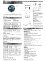
FUNCTIONS
BUTTON OPERATIONS
MODE Button
1.Press the MODE button to move between all functions in sequence as “ ”
from one function screen to another when the speed sensor does not detect any
signal input.
2.Press the MODE button to move partial functions in loop sequence as “ ”
when speed sensor detects signal input.
Max. 8mm
Vibration Direction
sensor
Max. 8mm
Vibration Direction
sensor
Functions SpecificationsSymbol
Bar tachometer
12,000rpm
Digital Tachometer
RPM
100 19,900 rpm, 100rpm increment
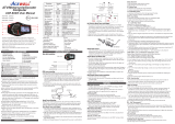
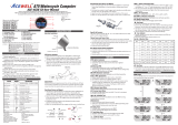
Models and Indicators
MD085-X52
MD085-X54
MD085-X56
MD085-X59

RESET Button
1. Press RESET button acts as a revised button operation of MODE button.
2. Press MODE or RESET button to the desired screen then press RESET
button for 2 seconds to reset TRIP 2, MAX SPD, MAX RPM and MAX TEMP1
or 2 data from stored values to zero individually. The maintain reminder data
will be reset to the preset value rather than zero.
3. The data of Trip 1, AVG SPD & R. Time will all be reset at the same time when
one of the 3 data functions is being reset.
4. ODO, clock, HR Time and T. Time data cannot be reset.
3. These values are approximate and will differ for different brands of tire, we would
always recommend that you measure the distance travelled per revolution of the
wheel in mm and enter this into the computer.
4.The computer calculates the wheel rotating length between 2 passes of the
magnet; use this table to find the settings when you are using a reed sensor or an
universal hall sensor with magnet to measure your speed.
5. If you are using a cable drive speed sensor then divide the number in the above
table by the number of turns of the cable drive for each revolution of the wheel.
For example if 1 wheel revolution equals 5 turns of speed cable then the wheel
circumference has to be divided 5.
6. You can use more magnets, but the wheel circumference setting must be divided
by the number of magnet you installed.
7. The computer has a built-in software divider setting from 1 to 199 for different
speed signal application, refer to the divider setup, one means one wheel
revolution creates one signal. You have to input the number of signal per wheel
revolution to have a correct speed.
1. The details below have been calculated using following formula: Tire
Diameter (inches) x 25.4(mm/inches) x 3.1416 = wheel circumference (in mm).
2. Identify the tire size of your ATV/Motorcycle when you need to change
different tire size and key in the corresponding number shown in the
following chart.
Shift Warning RPM Operation
1. Press MODE button to the RPM screen; pull on the throttle until the desired shift
warning RPM.
2. Press RESET button to confirm and set up the shift warning RPM.
3. Bar-graphic tachometer and warning LED will flash to warning you shift gear.
4. Press RESET button for 2 seconds at the RPM screen to re-adjust the shift
warning RPM
Backlight Color Adjust:
1. Press MODE button to get to the VOLT screen when not moving; push and hold
RESET button for 2 seconds to go into backlight color setting mode.
2. It displays “LED RGB and RX-GX-BX”, the X after R, G and B indicate each color
of Red, Green or Blue color to be adjustable, each color has 10 levels 0, 1, 2,.9 for
setting, “0” means the color is off, “9” means the color is turned on 100%.
3. Each press of the RESET button increments the flashing digit by 1, press MODE
button to confirm the flashing digit setting and jump to next digit to be set. Press
MODE button for 2 seconds to finish the setting and go to normal mode Trip 1.
Gear Indicator training operations:
1. Connects grey wire to N and purple wire to R..
2. Put bike to a rolling stand, turns on engine and keep at N gear.
3. Gear indicator shows “N”
4. Change the LCD screen to digital RPM.
5. Press and hold MODE button for 2 seconds to go into the number of gears setting
mode.
6. Gear indicator flashes the default 6 gears.
7. Press RESET button to select the number of gear, user can select 4-8 gears or “0”
to disable the gear function.
8. Press MODE button to confirm the number of gears and go to the number gear
ratio setting mode.
9. It displays and flashes “1”, shift bike’s gear to the 1st gear, run the engine to
between 2000-4000RPM.
10. Hold the speed and the RPM for about 5 seconds until the “-“flashing. The
flashing “-“ after the gear “1” means the 1st gear be set.
11. Press MODE button to confirm the set and go to the 2nd gear setting.
12. It displays and flashes “2”, shift bike’s gear to the 2nd gear, run the engine to
between 2000-4000RPM.
13. Hold the speed and the RPM for about 5 seconds until the “-“flashing. The
flashing “-“ after the gear “2” means the 2nd gear be set.
14. Press MODE button to confirm the setting and go to next gear setting.
15. Operates the same operations as items 11-14 to set other gears until the last
gear be set. Press MODE button to return to normal mode.
16. At gear indicator setting mode, press and hold MODE button for 2 seconds to
abort the setting if you need to re-set at any setting screen.
Distance timer, acceleration and deceleration timers setting mode
1. Press MODE or RESET button to the T. Time screen at parking status, press and
hold RESET button for 2 seconds to go into the 3 test timers select mode.
2. It displays SELECt and flashes DstTimer, press MODE button to move DstTimer,
AccTimer, DecTimer from one set mode to another set mode in loop sequence,
press and hold MODE button for 2 seconds at the one of the 3 select modes to go
into the testing mode.
3. At any testing mode, each press of MODE button converts items to be tested or no
function in case it has only item, press and hold MODE button for 2 seconds to
confirm and enter the item to be tested, the timer counts automatically when it
receive speed and auto-stop when finishes the timer. Each press RESET button to
return to last operated mode until the select mode. Press and hold the RESET
button for 2 seconds at any testing mode to jump to normal mode Trip 1 screen.
4. At Distance Timer testing mode, it displays DstTimer and flashing “100M”, each
press of MODE button converts 100M or 400M to be tested, press and hold MODE
button for 2 seconds to confirm the setting and go into the DstTimer testing screen
and flashing 00:00:00, the timer counts automatically when it receive speed signal
and auto-stop when trip meter reaches preset 100 or 400 meter. Press MODE
button to reset the tested timer to zero and preparing another new round test, it
displays DstTimer and flashes 00:00:00 again. Press and hold MODE button for 2
seconds to go out the TRIP RT test screen and return to Trip 1 screen.
5. At Acceleration test mode, it displays AccTimer and flashing “0-100”.
Follow the item 3 of button operation to finish the acceleration test or have another
test or jump to normal mode Trip1.
6. At deceleration test mode, it displays DecTimer and flashing “100-0”, Follow the
item 3 of button operation to finish the acceleration test or have another test or
Tire outside
diameter
Tire outside
diameter
Tire outside
diameter
Circumference
number
(mm)
Circumference
number
(mm)
Circumference
number
(mm)
23 inch
24 inch
25 inch
26 inch
19 inch
20 inch
21 inch
22 inch
15 inch
16 inch
17 inch
18 inch
1835
1915
1995
2075
1516
1596
1676
1756
1197
1277
1357
1436
WHEEL CIRCUMFERENCE TABLE
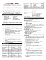
Clock, RPM, Wheel, Divider, Unit, Maintain, Thermometer, fuel meter and ODO SET UP
1. Setup operations include clock set, RPM shift warning, numbers of engine
rotation per signal, speed sensor type, wheel circumference, pulse set for signal
divider, units, decimal, maintain reminder, warning voltage, units of temperature
1, temperature 1 warning, units of temperature 2, temperature 2 warning, fuel
meter input resistance selection and odometer adjustment. These must be set
up step by step. The computer will automatically return to normal mode if no
button is pressed within 75 seconds.
2. Press both MODE & RESET buttons to go into setting mode. In setting mode,
each press of the RESET button increments the flashing digit by 1 or converts
units. Press MODE button to confirm the digit setting and warning jump to next
digit or next setting screen to be set. Press MODE button for 2 seconds at any
setting screen to finish the setting and go to normal mode.
3. It displays "CLOCKset, XX:XX and flash 12H or 24H" symbols as well AM/PM
after XX:XX in case you select 12H. Operate buttons as shown in section 2 to
set the clock and jump to shift RPM warning setting.
4. It displays the default "RPMset and 06500", the digit “06” flash. Using mode and
reset buttons set the RPM shift warning and jump to engine specification setting.
5. It displays "RPM_NUM 1r1P", the default value is 1r1P; there are 5 options:
1r1P, 2r1P, 3r1P, 1r2P, 1r4P. “r” means the numbers of engine rotation, “P”
means number of signals from engine or coil. For example the value 2r1P
means the engine rotate 2 turns for one pulse generated.
6. Press the RESET button to loop through each of the 5 options. Press MODE
button to confirm the choice one and go to speed sensor type setting screen.
7. It displays “SPD_TYPE and flash HALL or REED”. Using mode and reset
buttons set speed sensor and jump to wheel circumference setting.
8. It displays "WHEELset and XXXX" the 1st X is flashing, flashing digit is digit to
be set. Using mode and reset buttons set the wheel circumference and jump to
signal divider setting.
9. It displays "PULSEset and 001" for signals to be divided. Using mode and reset
buttons set the correct value for the installation and jump to unit setting. Using
mode and reset buttons set the correct value for the installation.
10. It displays “UNIT SET and flash KM/H or MPH”. Using mode and reset buttons
set the correct value for the installation the unit setting and jump to decimal
point setting.
11. It displays “DECIMAL 99.9Km/H and flash ON” or “DECIMAL 99Km/H and flash
OFF”, the decimal point will be disappeared in case Off is selected. Using mode
and reset buttons set the decimal and jump to maintain reminder setting.
12. It displays “FIX MODE and flash HR. OFF or DST”, HR is setting by hour
meter and DST is setting by trip meter as the maintain reminder. Using mode
and reset buttons set the maintain reminder and jump to voltage warning
setting. The maintain reminder function will be disappear when select “OFF”.
13. There are 3 voltage warning value VOLT_ON, VOLT_OFF and VOLT_HI to be
set in the order.
14. It displays “VOLT_ON and a flashing numbers XX.X of voltage” to be set,
“VOLT_ON” means battery warning on voltage – when the voltage falls below
this the LED will come on, setting range from 11.0 to 14.9V. “VOLT_OFF”
means battery warning off voltage, setting range from 11.0 to 14.9V to, but
VOLT_OFF voltage must larger than VOLT_ON voltage– when this voltage is
exceeded the LED will go off.. “VOLT-HI” means battery warning on voltage –
when the voltage is exceeded the LED will come on, setting range from 11.0 to
15.0V“. Using mode and reset buttons set the voltage warning and jump to
thermometer 1 unit setting.
15. It displays "T1_UNIT and flash ºC, ºF, OFF or HI", each press of RESET button
converts ºC, ºF, OFF or HI, the temperature bars will disappear when you select
oFF mode, the “T1_UNIT HI” mode is for other NTC ON/OFF sensors to show
over temperature warning, digital temperature meter will be disable, NTC
sensor sends a low signal to ground, backlight and last bar of bar-temperature
be flash to show over temperature warning at this mode; press MODE button to
confirm temperature setting and jump to temperature 1 warning setting.
16. It displays "T1_WARN and XXX" and the selected unit. Using mode and reset
buttons set the temperature warning and go to thermometer 2 UNIT setting.
17. thermometer 2 setting It displays "T2_UNIT and flash ºC,ºFor OFF", each
press of RESET button converts ºC,ºF or OFF, the T2 will disappear when you
select OFF mode; press MODE button to confirm temperature setting and jump
to fuelsensor resistance setting.
18. It displays “FUEL_SET and flash F10 E100”, there are options of F10 E250,
F10 E510, F30 E80, F100E10,F250E10, F510E10,F80 E30, RES and OFF,
Using mode and reset buttons set a resistance same as your fuel sender and
jump to odometer setting. The fuel meter bar will disappear if you select oFF
mode. In “RES” mode connecting the input wire to 0v can bring on the fuel
symbol and/or LED indicator instantly.
speed siginal input
19. It displays “ODOset, KM/H or MPH and 00000X”, the “X” is from odometer
testing in factory, follow item 2 to setting a desired odometer and jump to clock
setting or return to Normal Mode. This setting screen will disappear when the
odometer is over 30km (18.6Miles) or your setting is over 30km.
2
0
4
6
8
10
12
2
0
4
6
8
10
12
2
0
4
6
8
10
12
2
0
4
6
8
10
12
2
0
4
6
8
10
12
2
0
4
6
8
10
12
2
0
4
6
8
10
12
2
0
4
6
8
10
12
2
0
4
6
8
10
12
2
0
4
6
8
10
12
2
0
4
6
8
10
12
2
0
4
6
8
10
12
2
0
4
6
8
10
12
2
0
4
6
8
10
12
2
0
4
6
8
10
12
2
0
4
6
8
10
12
Mode
Mode
Mode
Mode
Mode
Mode
Mode
Mode
Mode
Mode
Mode
Mode
Mode
Mode
Mode
Mode
2
0
4
6
8
10
12
2
0
4
6
8
10
12
RESET
2SEC
2
0
4
6
8
10
12
2
0
4
6
8
10
12
2
0
4
6
8
10
12
2
0
4
6
8
10
12
2
0
4
6
8
10
12
2
0
4
6
8
10
12
2
0
4
6
8
10
12
2
0
4
6
8
10
12
2
0
4
6
8
10
12
2
0
4
6
8
10
12
2
0
4
6
8
10
12
2
0
4
6
8
10
12
2
0
4
6
8
10
12
2
0
4
6
8
10
12
2
0
4
6
8
10
12
2
0
4
6
8
10
12
2
0
4
6
8
10
12
2
0
4
6
8
10
12
2
0
4
6
8
10
12
2
0
4
6
8
10
12
MODE
+
RESET
2SEC
MODE
Mode
Mode
Mode
Mode
Mode
Mode
Mode
Mode
Mode
Mode
Mode
Mode
Mode
Mode
Mode
Mode
Mode
2SEC
Mode
Mode
-
 1
1
-
 2
2


Acewell ACE-MD085-254 User manual
- Category
- Bicycle accessories
- Type
- User manual
- This manual is also suitable for
Ask a question and I''ll find the answer in the document
Finding information in a document is now easier with AI
Related papers
-
 Acewell MA-085-3 Series User manual
-
 Acewell ACE-64 Series User manual
-
 Acewell MD-052-3 Series User manual
-
 Acewell ACE-28 series User manual
-
 Acewell ACE-2956 series User manual
-
 Acewell CA-085-15 Series User manual
-
 Acewell ACE-43 Series User manual
-
 Acewell ACE-31 SERIES User manual
-
 Acewell ACE-3968-XX User manual
-
 Acewell ACE-395X-XX series User manual


Other documents
-
PYLE Audio PBKCM4WL User manual
-
Giant Continuum 9W User manual
-
-
 HER CHEE ACE-7XXX series User manual
-
Dakota Digital MCL-2011(-R) User manual
-
-
-
-
-
