Page is loading ...

The motherboard or video card should be removed from the chassis in order
to install the chipset cooler. The mounting screws are inserted from the back
side of the board.
CAUTION: Removal of the original heat sink my void your
manufacturer’s hardware warranty. Please consult the
manufacturer if unsure, and keep all original parts in case of a
return/RMA. Koolance does not recommend using a liquid cooler
on motherboards or video cards that lack standard mounting holes,
or have heat sinks that are attached with only an adhesive (rather
than screws or bolts).
!
CHC-120, GPU-200 Installation Guide v 1.2
1 2
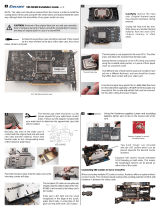
Remove the retention springs from the heatsink by
applying pressure with your fi nger until the spring
may be unclasped.
Remove Heatsink
Screw-Mounted
Retention Spring (Motherboards)
Apply Thermal Paste
Through the original mounting
holes, insert both metal mounting
screws from the back of the board.
Make sure the plastic insulating
washers are placed on each screw.
Attach Mount Screws (If Applicable)
Beneath the motherboard/video card, the
plastic tabs must be squeezed together
with needle-nose pliers in order to free the
original heat sink. (Some tabs have locking
center pins which must fi rst be removed
from the top.)
Once loosened, remove the original
heat sink. Apply a thin layer of thermal
interface compound onto the chipset if
necessary.
Also place plastic insulating washers
on each screw on the front side of the
motherboard or video card. Tighten both
mounting screw posts to each screw by
hand. These will be used to secure the
cooler.

3 4
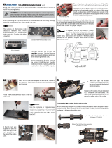
If you have retention springs,
use the appropriate length of
retention spring included to
secure the cooler.
Place the
cooler on
your chipset.
If you have a screw
mount, set the bracket
on the cooler. Be sure
to fi t the bracket arms
over the mounting
post screws.
Tighten thumb nuts
to mounting post
screws by hand.
The cooler should
now be secure.
Remove the protective fi lm from
the cooling block.
Install Cooler
Screw-Mounted
Retention Spring
The bracet included
is designed to fi t a
range of mounting
post spaces.
43.2 mm - 93.7 mm
1.70” - 3.69”
/


